EP1102294A2 - Drehknopf mit Tastfunktion - Google Patents
Drehknopf mit Tastfunktion Download PDFInfo
- Publication number
- EP1102294A2 EP1102294A2 EP00122924A EP00122924A EP1102294A2 EP 1102294 A2 EP1102294 A2 EP 1102294A2 EP 00122924 A EP00122924 A EP 00122924A EP 00122924 A EP00122924 A EP 00122924A EP 1102294 A2 EP1102294 A2 EP 1102294A2
- Authority
- EP
- European Patent Office
- Prior art keywords
- rotary knob
- button
- rotary
- key
- holder
- Prior art date
- Legal status (The legal status is an assumption and is not a legal conclusion. Google has not performed a legal analysis and makes no representation as to the accuracy of the status listed.)
- Granted
Links
- 238000005286 illumination Methods 0.000 claims description 7
- 230000005540 biological transmission Effects 0.000 description 6
- 230000004913 activation Effects 0.000 description 1
- 230000008878 coupling Effects 0.000 description 1
- 238000010168 coupling process Methods 0.000 description 1
- 238000005859 coupling reaction Methods 0.000 description 1
- 230000009365 direct transmission Effects 0.000 description 1
- 230000009349 indirect transmission Effects 0.000 description 1
- 230000007246 mechanism Effects 0.000 description 1
- 230000003134 recirculating effect Effects 0.000 description 1
- 238000010079 rubber tapping Methods 0.000 description 1
- 239000000523 sample Substances 0.000 description 1
Images


Classifications
-
- G—PHYSICS
- G05—CONTROLLING; REGULATING
- G05G—CONTROL DEVICES OR SYSTEMS INSOFAR AS CHARACTERISED BY MECHANICAL FEATURES ONLY
- G05G1/00—Controlling members, e.g. knobs or handles; Assemblies or arrangements thereof; Indicating position of controlling members
- G05G1/08—Controlling members for hand actuation by rotary movement, e.g. hand wheels
- G05G1/10—Details, e.g. of discs, knobs, wheels or handles
- G05G1/105—Details, e.g. of discs, knobs, wheels or handles comprising arrangements for illumination
-
- H—ELECTRICITY
- H01—ELECTRIC ELEMENTS
- H01H—ELECTRIC SWITCHES; RELAYS; SELECTORS; EMERGENCY PROTECTIVE DEVICES
- H01H25/00—Switches with compound movement of handle or other operating part
- H01H25/06—Operating part movable both angularly and rectilinearly, the rectilinear movement being along the axis of angular movement
- H01H25/065—Operating part movable both angularly and rectilinearly, the rectilinear movement being along the axis of angular movement using separate operating parts, e.g. a push button surrounded by a rotating knob
-
- H—ELECTRICITY
- H01—ELECTRIC ELEMENTS
- H01H—ELECTRIC SWITCHES; RELAYS; SELECTORS; EMERGENCY PROTECTIVE DEVICES
- H01H9/00—Details of switching devices, not covered by groups H01H1/00 - H01H7/00
- H01H9/18—Distinguishing marks on switches, e.g. for indicating switch location in the dark; Adaptation of switches to receive distinguishing marks
- H01H9/182—Illumination of the symbols or distinguishing marks
Definitions
- the invention relates to a rotary knob with push button function according to the preamble of the patent claim 1.
- Rotary knobs with pushbutton function which are part of a rotary switch and / or rotary control, are used in control units, for example in automotive engineering.
- Such a rotary knob is disclosed in DE 196 36 643 C1, in which a The top of the knob is felt out. The keying itself takes place in the center via additional ones Switching mechanisms.
- a button is activated in addition to the button The symbols on the top of the button are adjusted. This is particularly disadvantageous if the symbolism of the key must always remain horizontally in the same position. On Another problem arises if, in addition to a central illumination of the functional lighting the button should also be used for centric contacting.
- the object of the invention is to show a rotary knob in which one located in the rotary knob The button remains horizontal when the rotary head is adjusted. Another subtask arises with regard to a central illumination of the button and a central contact when touched.
- the invention is based on the idea of a rotary knob and a key located therein build up functionally detached from each other by a bracket, which makes adjustment the button is not adjusted with the rotary knob.
- the bracket is the constructive one Connection between the rotary knob and the button.
- the rotary adjustment is made by the Transfer the rotary knob while the button function is carried out using the separate button.
- a flexible switch plunger with a central bushing around which the contacts are preferred are attached in a circular shape. The light necessary for the illumination can be through the implementation can be initiated in the button.
- a counterpart of the rotary knob is movably mounted on the bracket while the Button is firmly connected to the bracket.
- the advantage here is that the button is not must be specially aligned to a base or printed circuit board, as the turntable as compact item is executable. When the turntable is fastened in a panel this can also be done using the bracket.
- the bracket can also be attached to the counterpart of the rotary knob in the rotary switch or be part of the counterpart.
- the transmission of the torques takes place directly or indirectly, whereby for the direct transmission a layer plate is attached to the counterpart of the rotary knob, while for one indirect transmission is provided on the counterpart all-round gearing, so that the Rotation transmission to an electronic component takes place off-center.
- a rotary actuator 1 is shown in a compact design, which consists of a hollow knob 2 with a knob bottom part 3 as a counterpart.
- This rotary actuator 1 is installed in a panel 4, for example a front panel of a motor vehicle control unit.
- a button 5 is also integrated in the rotary knob 2 and is held mechanically by a holder 6.
- the lower part of the rotary knob 3 is loosely placed on the holder 6.
- the key 5 has vertical guide grooves 5.1, in which the holder 6 engages with its holding fingers 6.1 and as a result the key 5 is connected to the holder 6 in a rotationally secure manner.
- Three guide grooves 5.1 should preferably be provided for a uniform keying.
- the tactile path is limited by a depression 2.1 in the rotary knob 2 and the length of the guide groove 5.1.
- the key 5 is preferably a hollow probe element, so that the holding fingers 6.1 engage within the key 5.
- the key 5 also has a light guide 9, which is preferably guided on one side within the key 5 and projects into the head region of the key 5 for illuminating a key symbol 10.
- the key 5 engages a contact dome 11.1 of a switching plunger 11, which has a central passage 11.2 for the light of a light element 12, for example an LED, when this light guide 9 is pressed. A central contacting of the contacts in the switching plunger 11 and the contacts of a printed circuit board 13 takes place via this contact dome 11.1.
- the lower part 3 of the rotary knob has a layer plate 14 which makes contact with a further contact element 15 of the printed circuit board 13.
- the holder 6 itself prevents the key 5 from being rotated when the rotary knob 2 is rotated, but does not prevent the layer plate 14 from being adjusted to the contact element 15, which taps off a different voltage value.
- the assembly of the individual elements in the Aperture 4 is fixed.
- the holder 6 points, for example, from the space between two holding fingers 6.1 outgoing, preferably two U-shaped latching elements 6.2, a space for tapping the voltage value 15 is maintained.
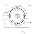
- a rotary switch 20 with push button function is shown. This can be integrated in a housing 24 as a counterpart for a hollow rotary knob 23 behind a panel 19, for example a front panel of a motor vehicle operating unit (FIG. 2a).
- a light plate 22 with activation is attached below the symbols 21.
- the rotary switch 20 has a button 30 in the rotary knob 23, which is axially supported in the rotary knob 23 and in the housing 24 and has a defined stroke relative to the housing 24.
- the key 30 is guided through a holder 24.1 of the housing 24 when pressed.
- a light block 31 is integrated, through which the light from an LED 32 of a circuit board 25 is directed to a function display 33 indicating the function of the key 30.
- Another symbol 34 indicating the functional symbolism of the key 30, for example 'recirculating air' (FIG. 2a) is located in the upper part of the key 30 and is illuminated by another LED 35 on the printed circuit board 25.
- This switching plunger 36 is preferably provided with an additional lens system 38 above the central bushing 36.1.
- the light of the LED 35 reaches the symbol 34 via this lens system 38, for example via a hollow part 39 of the key 30.
- the keying takes place from the rotary knob 23.
- the key 30 is moved with the light block 31 and the hollow part 39 in the direction of the circuit board 25, the key 30 engaging via the lens system 38 on the head part 37 of the switching plunger 36, which yields to the pressure. Below the switching plunger 36, the contacts of the switching plunger 36 then come into contact with contacts of the printed circuit board 25.
- the light block 31 is simultaneously adjusted in the direction of the LED 32, as a result of which a better light coupling for the function display 33 takes place.
- the transmission of the rotary adjustment of the rotary knob 23 can be directly and centrally via a Layer plate not shown here take place below the rotary knob 23.
- the bracket 24.1 is designed so that when the knob top 23 is turned, the button 30 in their starting position remains.
- An indirect, off-center transmission of the rotary adjustment to an electronic component, for example, a potentiometer 40 of the rotary switch 20 is via a toothing 26 possible on the rotary knob 23.
- This potentiometer 40 can also be adjusted when keyed be what the rotary switch 20 has a pinion 27, which adjusts when keyed becomes.
- This type of toothing can also be attached to the rotary knob 2 of the rotary actuator 1 (not shown in detail), which also causes an off-center transmission of the rotary adjustment would be done.
- Fig. 3 is based on the prior art with the hollow rotary knob 23 a layer plate 38 connected, for example to a rotational resistance.
- the layer plate 38 is preferably located below the light plate 22, which is preferably is integrated in the rotary knob 23.
- the keying is done as described using the key 30, the illumination of the key symbols 10 via the implementation 36.1 of the switching plunger 36.
- the use of the rotary knob 2, 23 is not limited to automotive engineering. So the rotary knob 2, 23 can also be used in control panels, consoles etc.
Landscapes
- Physics & Mathematics (AREA)
- General Physics & Mathematics (AREA)
- Engineering & Computer Science (AREA)
- Automation & Control Theory (AREA)
- Switches With Compound Operations (AREA)
- Rotary Switch, Piano Key Switch, And Lever Switch (AREA)
- Switch Cases, Indication, And Locking (AREA)
- Mechanical Control Devices (AREA)
Abstract
Description
einen Drehsteller mit Tastfunktion,
einen Drehschalter mit Tastfunktion,
eine Variante des Drehschalters aus Fig. 2.
Vorzugsweise ist die Taste 5 ein hohles Tastelement, so daß die Haltefinger 6.1 innerhalb der Taste 5 eingreifen. Die Taste 5 weist des weiteren einen Lichtleiter 9 auf, der vorzugsweise einseitig innerhalb der Taste 5 geführt wird und in den Kopfbereich der Taste 5 zur Ausleuchtung einer Tastensymbolik 10 hineinragt.
In einer bevorzugten Ausführung greift die Taste 5 bei Tastung über diesen Lichtleiter 9 auf einen Kontaktdom 11.1 eines Schaltstößels 11, der eine zentrische Durchführung 11.2 für das Licht eines Lichtelementes 12 , beispielsweise eine LED, aufweist. Über diesen Kontaktdom 11.1 erfolgt dabei eine zentrische Kontaktierung der Kontakte im Schaltstößel 11 sowie der Kontakte einer Leiterplatte 13.
Für die Übertragung der Drehinformation des Drehstellers 1 auf ein elektronisches Bauelement (nicht näher dargestellt) weist das Drehknopfunterteil 3 eine Schichtplatte 14 auf, die mit einem weiteren Kontaktelement 15 der Leiterplatte 13 kontaktiert. Die Halterung 6 selbst verhindert das Verdrehen der Taste 5 beim Drehen des Drehknopfes 2, jedoch nicht das Verstellen der Schichtplatte 14 zum Kontaktelement 15, das dabei einen anderen Spannungswert abgreift.
Der Drehschalter 20 weist im Drehknopf 23 eine Taste 30 auf, die im Drehknopf 23 und im Gehäuse 24 axial gelagert ist und einen definierten Hub gegenüber dem Gehäuse 24 besitzt. Die Taste 30 wird durch eine Halterung 24.1 des Gehäuses 24 bei Tastung geführt.
Die Tastung erfolgt aus dem Drehknopf 23 heraus. Dabei wird die Taste 30 mit dem Lichtstein 31 und dem hohlen Teil 39 in Richtung Leiterplatte 25 bewegt, wobei die Taste 30 über das Linsensystem 38 an das Kopfteil 37 des Schaltstößels 36 angreift, welches dem Druck nachgibt. Unterhalb des Schaltstößels 36 kommt es dann zur Kontaktierung der Kontakte des Schaltstößels 36 mit Kontakten der Leiterplatte 25. Der Lichtstein 31 wird hierbei gleichzeitig in Richtung LED 32 verstellt, wodurch eine bessere Lichteinkopplung für die Funktionsanzeige 33 erfolgt.
Claims (6)
- Drehknopf mit Tastfunktion zur Betätigung eines Bedienteils, wobei der Drehknopf hohl ausgeführt ist und ein Gegenstück aufweist, das mit einem geräteseitigen Betätigungsorgan elektrisch verbunden ist, dadurch gekennzeichnet, daß der Drehknopf (2,23) und die Taste (5, 30 ) von einer im Drehknopf (2, 23) befindlichen Halterung ( 6, 24.1) getragen und durch diese getrennt voneinander betätigt werden.
- Drehschalter nach Anspruch 1, dadurch gekennzeichnet, daß unterhalb der Taste (5, 30) ein Schaltstößel (11, 36) mit zentrischer Durchführung (11.2, 36.1) angebracht ist, wodurch eine zentrische Ausleuchtung einer Tastensymbolik (10, 34) der Taste (5, 30) und eine zentrische Kontaktierung unterhalb der Taste (5, 30) erfolgt.
- Drehknopf nach Anspruch 1 oder 2, dadurch gekennzeichnet, daß ein als Gegenstück (3) fungierendes Drehknopfunterteil auf der Halterung (6) mechanisch losgelöst von der Halterung (6) gelagert ist, die Halterung (6) mit Haltefingern (6.1) in Führungsnute (5.1) der Taste (5) eingreift, wodurch die Taste (5) mit der Halterung (6) fest verbunden ist.
- Drehknopf nach Anspruch 1 oder 2, dadurch gekennzeichnet, daß die Halterung (24.1) fest in einem als Gegenstück (24) fungierendem Gehäuse eingebunden ist, während die Taste (30) innerhalb der Halterung (24.1) beweglich geführt wird.
- Drehknopf nach einem der Ansprüche 1 bis 4, dadurch gekennzeichnet, daß am Drehknopf (2, 23) Schichtplatten (14, 38) angebracht sind.
- Drehknopf nach einem der Ansprüche 1 bis 5, dadurch gekennzeichnet, daß am Drehknopf (2, 23) eine Rundumverzahnung (26) angebracht ist, mit der ein Potentiometer (40) außermittig verstellt wird.
Applications Claiming Priority (2)
| Application Number | Priority Date | Filing Date | Title |
|---|---|---|---|
| DE19964131A DE19964131A1 (de) | 1999-11-22 | 1999-11-22 | Drehknopf mit Tastfunktion |
| DE19964131 | 1999-11-22 |
Publications (3)
| Publication Number | Publication Date |
|---|---|
| EP1102294A2 true EP1102294A2 (de) | 2001-05-23 |
| EP1102294A3 EP1102294A3 (de) | 2003-04-02 |
| EP1102294B1 EP1102294B1 (de) | 2005-05-11 |
Family
ID=7935227
Family Applications (1)
| Application Number | Title | Priority Date | Filing Date |
|---|---|---|---|
| EP00122924A Expired - Lifetime EP1102294B1 (de) | 1999-11-22 | 2000-10-21 | Drehknopf mit Tastfunktion |
Country Status (5)
| Country | Link |
|---|---|
| US (1) | US6667446B1 (de) |
| EP (1) | EP1102294B1 (de) |
| JP (1) | JP2001189117A (de) |
| DE (2) | DE19964131A1 (de) |
| ES (1) | ES2239990T3 (de) |
Cited By (10)
| Publication number | Priority date | Publication date | Assignee | Title |
|---|---|---|---|---|
| DE10147793C1 (de) * | 2001-09-27 | 2003-02-13 | Miele & Cie | Druck-Dreh-Schalter |
| DE10151016A1 (de) * | 2001-10-16 | 2003-04-24 | Volkswagen Ag | Bedienvorrichtung für eine Klimaanlage eines Kraftfahrzeuges |
| WO2005034158A3 (de) * | 2003-09-16 | 2005-06-09 | Trw Automotive Electron & Comp | Drehschalter in einem kraftfahrzeug |
| EP1598723A3 (de) * | 2004-05-18 | 2007-02-28 | Lacroix Electronique SRL | Thermostat für Strahlheizkörper mit verbesserten Steuermitteln |
| EP1879094A1 (de) * | 2006-07-11 | 2008-01-16 | Delphi Technologies, Inc. | Knopfanordnung |
| EP1884857A1 (de) | 2006-07-31 | 2008-02-06 | Delphi Technologies, Inc. | Drehknopf mit Anzeige |
| WO2011113733A1 (fr) * | 2010-03-17 | 2011-09-22 | Delphi Technologies, Inc. | Dispositif de commande a commutateur rotatif retro-eclaire par un guide de lumiere |
| CN102729827A (zh) * | 2012-06-25 | 2012-10-17 | 惠州市德赛西威汽车电子有限公司 | 一种汽车内饰旋钮结构 |
| CN101504893B (zh) * | 2008-02-07 | 2013-09-04 | 福特全球技术公司 | 用于机动车辆的照明开关 |
| WO2024209279A1 (fr) | 2023-04-06 | 2024-10-10 | Compagnie Industrielle Des Chauffe-Eau | Interface homme-machine à molette de sélection, système de chauffage et/ou de refroidissement la comprenant, et système de ventilation mécanique contrôlée la comprenant |
Families Citing this family (33)
| Publication number | Priority date | Publication date | Assignee | Title |
|---|---|---|---|---|
| DE10239386A1 (de) * | 2002-03-01 | 2003-09-18 | Volkswagen Ag | Verfahren zum Betrieb einer Anzeigeeinrichtung im Kraftfahrzeug sowie Anzeigeeinrichtung selbst |
| DE10255480B3 (de) * | 2002-11-28 | 2004-03-04 | Preh-Werke Gmbh & Co. Kg | Bedienelement |
| US7105754B2 (en) * | 2003-06-03 | 2006-09-12 | Fender Musical Instruments Corporation | Multi-functional control assembly for use in electric guitars |
| DE10342325B4 (de) * | 2003-09-11 | 2009-10-08 | Preh Gmbh | Optischer Inkrementgeber mit Drucktaster |
| JP4299089B2 (ja) * | 2003-09-24 | 2009-07-22 | 株式会社東海理化電機製作所 | 車両用空調装置の操作装置 |
| US7636748B2 (en) * | 2003-09-29 | 2009-12-22 | Microsoft Corporation | Display configurations for a data processing device |
| US7205495B2 (en) * | 2004-01-12 | 2007-04-17 | Stanton Magnets, Inc. | Control knob with multi-color indicator |
| US20050161311A1 (en) * | 2004-01-12 | 2005-07-28 | James Mazur | Control knob with multi-color indicator |
| JP4031775B2 (ja) | 2004-04-28 | 2008-01-09 | 三菱重工業株式会社 | 車両用空調装置のダイヤル式スイッチ機構 |
| US20050270779A1 (en) * | 2004-06-08 | 2005-12-08 | James Mazur | Light projection rotary control indicator |
| US7091437B2 (en) * | 2004-10-06 | 2006-08-15 | Premier Image Technology Corporation | Rotary switch |
| DE102004054178B4 (de) * | 2004-11-10 | 2010-09-02 | Preh Gmbh | Bedienelement für Steuergeräte in Kraftfahrzeugen |
| US6983717B1 (en) * | 2005-01-05 | 2006-01-10 | Yazaki North America, Inc. | Indicator assembly with halo-free pointer |
| JP4384065B2 (ja) * | 2005-02-17 | 2009-12-16 | パナソニック株式会社 | 電子装置 |
| JP2006260943A (ja) * | 2005-03-17 | 2006-09-28 | Matsushita Electric Ind Co Ltd | 照光付き回転型電子部品の実装構造 |
| JP4481871B2 (ja) * | 2005-04-28 | 2010-06-16 | アルプス電気株式会社 | スイッチ装置 |
| DE102006026187B4 (de) * | 2006-05-30 | 2010-04-29 | E.G.O. Elektro-Gerätebau GmbH | Bedieneinrichtung für ein Elektrogerät und Elektrogerät |
| US7479607B2 (en) * | 2006-07-28 | 2009-01-20 | Bose Corporation | Control knob with safety feature |
| JP5117994B2 (ja) * | 2008-10-24 | 2013-01-16 | 株式会社東海理化電機製作所 | ダイヤル装置 |
| US8178805B2 (en) * | 2009-01-19 | 2012-05-15 | Illinois Tool Works Inc. | Appliance control knob providing illuminated setting indication |
| DE102010017992B3 (de) * | 2010-04-23 | 2011-03-24 | MENTOR GmbH & Co. Präzisions-Bauteile KG | Beleuchtbarer Bedienknopf |
| DE102010017995B3 (de) * | 2010-04-23 | 2011-06-16 | MENTOR GmbH & Co Präzisions-Bauteile KG | Beleuchtbarer Bedienknopf |
| US8813676B2 (en) | 2010-05-07 | 2014-08-26 | Whirlpool Corporation | User interface for a controller |
| TWI423291B (zh) * | 2010-09-03 | 2014-01-11 | Primax Electronics Ltd | 旋鈕機構 |
| EP2707239A1 (de) | 2011-05-13 | 2014-03-19 | Volkswagen Aktiengesellschaft | Anzeigeeinheit für ein fahrzeug |
| US9902265B2 (en) * | 2011-05-13 | 2018-02-27 | Volkswagen Ag | Display device for a vehicle, and vehicle |
| CN102810420A (zh) * | 2011-05-30 | 2012-12-05 | 苏州市吴中区东方成套电器设备有限公司 | 一种带有指示功能的急停按钮 |
| FR2976685B1 (fr) | 2011-06-15 | 2013-11-01 | Fagorbrandt Sas | Dispositif de commande d'un appareil electromenager |
| CN102856110B (zh) * | 2011-06-30 | 2015-03-25 | 比亚迪股份有限公司 | 一种旋按组合钮 |
| DE102011083524B4 (de) | 2011-09-27 | 2017-04-06 | Behr-Hella Thermocontrol Gmbh | Dreh-/Drück-Bedienvorrichtung für ein Mensch-Maschine-Interface |
| GB2524813B (en) * | 2014-04-03 | 2016-03-23 | Naim Audio Ltd | An illuminated display panel for an electronic device |
| US9607792B2 (en) | 2014-12-18 | 2017-03-28 | Whirlpool Corporation | Knob assemblies with encoder-controlled illumination |
| US10850383B1 (en) | 2019-08-29 | 2020-12-01 | Ingersoll-Rand Industrial U.S., Inc. | Tool user interface ring |
Family Cites Families (16)
| Publication number | Priority date | Publication date | Assignee | Title |
|---|---|---|---|---|
| DE605324C (de) | 1934-11-08 | Siemens Schuckertwerke Akt Ges | Metalldampfgrossgleichrichter | |
| DE7313235U (de) * | 1973-07-05 | Vaillant J Kg | Anordnung an einer Handhabe | |
| DE8912785U1 (de) * | 1989-10-28 | 1989-12-28 | Preh-Werke GmbH & Co. KG, 97616 Bad Neustadt | Tandem-Potentiometer |
| JPH03127294U (de) * | 1990-04-05 | 1991-12-20 | ||
| GB2267554B (en) * | 1992-06-01 | 1995-08-02 | Matsushita Electric Industrial Co Ltd | Heating apparatus |
| FR2699871B1 (fr) * | 1992-12-28 | 1995-02-17 | Valeo Thermique Habitacle | Tableau de commande de chauffage ou climatisation de véhicule. |
| JPH0741917U (ja) * | 1993-12-22 | 1995-07-21 | マツダ株式会社 | 回転式パルススイッチユニット |
| DE19633892A1 (de) * | 1996-08-22 | 1998-02-26 | Bayerische Motoren Werke Ag | Drehknopf mit einem integrierten Drucktaster |
| DE19636643C1 (de) * | 1996-09-10 | 1998-02-12 | Preh Elektro Feinmechanik | Drehknopfoberteil |
| JP3706701B2 (ja) * | 1996-11-28 | 2005-10-19 | キヤノン株式会社 | 操作装置 |
| JP3549377B2 (ja) * | 1997-10-08 | 2004-08-04 | アルプス電気株式会社 | プッシュスイッチ付回転型電気部品 |
| JP3766207B2 (ja) * | 1998-05-25 | 2006-04-12 | アルプス電気株式会社 | 複合操作型電気部品 |
| DE19832678A1 (de) * | 1998-07-21 | 2000-02-10 | Mannesmann Vdo Ag | Schaltungsanordnung mit einem Drehgeber |
| DE19853587A1 (de) * | 1998-11-20 | 2000-05-25 | Fahrzeugklimaregelung Gmbh | Schaltvorrichtung |
| US6236002B1 (en) * | 2000-05-03 | 2001-05-22 | Shin Jiuh Corp. | Multiple switch assembly including cam operated rotary switch contacts and axially located pushbutton switch |
| US6262378B1 (en) * | 2000-05-03 | 2001-07-17 | Shin Jiuh Corp. | Rotary switch |
-
1999
- 1999-11-22 DE DE19964131A patent/DE19964131A1/de not_active Withdrawn
-
2000
- 2000-10-21 ES ES00122924T patent/ES2239990T3/es not_active Expired - Lifetime
- 2000-10-21 EP EP00122924A patent/EP1102294B1/de not_active Expired - Lifetime
- 2000-10-21 DE DE50010276T patent/DE50010276D1/de not_active Expired - Lifetime
- 2000-11-17 JP JP2000351207A patent/JP2001189117A/ja active Pending
- 2000-11-22 US US09/717,107 patent/US6667446B1/en not_active Expired - Fee Related
Cited By (17)
| Publication number | Priority date | Publication date | Assignee | Title |
|---|---|---|---|---|
| DE10147793C1 (de) * | 2001-09-27 | 2003-02-13 | Miele & Cie | Druck-Dreh-Schalter |
| DE10151016A1 (de) * | 2001-10-16 | 2003-04-24 | Volkswagen Ag | Bedienvorrichtung für eine Klimaanlage eines Kraftfahrzeuges |
| US7550686B2 (en) | 2003-09-16 | 2009-06-23 | Trw Automotive Electronics & Components Gmbh & Co., Kg | Rotary switch in a motor vehicle |
| WO2005034158A3 (de) * | 2003-09-16 | 2005-06-09 | Trw Automotive Electron & Comp | Drehschalter in einem kraftfahrzeug |
| EP1598723A3 (de) * | 2004-05-18 | 2007-02-28 | Lacroix Electronique SRL | Thermostat für Strahlheizkörper mit verbesserten Steuermitteln |
| EP1879094A1 (de) * | 2006-07-11 | 2008-01-16 | Delphi Technologies, Inc. | Knopfanordnung |
| US7342186B2 (en) | 2006-07-11 | 2008-03-11 | Delphi Technologies, Inc. | Knob force transfer module |
| US7462795B2 (en) | 2006-07-31 | 2008-12-09 | Delphi Technologies, Inc. | Rotary knob with a display |
| EP1884857A1 (de) | 2006-07-31 | 2008-02-06 | Delphi Technologies, Inc. | Drehknopf mit Anzeige |
| CN101504893B (zh) * | 2008-02-07 | 2013-09-04 | 福特全球技术公司 | 用于机动车辆的照明开关 |
| WO2011113733A1 (fr) * | 2010-03-17 | 2011-09-22 | Delphi Technologies, Inc. | Dispositif de commande a commutateur rotatif retro-eclaire par un guide de lumiere |
| FR2957692A1 (fr) * | 2010-03-17 | 2011-09-23 | Delphi Tech Inc | Dispositif de commande a commutateur rotatif retro-eclaire par un guide de lumiere |
| US8757825B2 (en) | 2010-03-17 | 2014-06-24 | Delphi Technologies, Inc. | Control device with rotary switch back-lit by a light guide |
| CN102729827A (zh) * | 2012-06-25 | 2012-10-17 | 惠州市德赛西威汽车电子有限公司 | 一种汽车内饰旋钮结构 |
| CN102729827B (zh) * | 2012-06-25 | 2016-01-06 | 惠州市德赛西威汽车电子股份有限公司 | 一种汽车内饰旋钮结构 |
| WO2024209279A1 (fr) | 2023-04-06 | 2024-10-10 | Compagnie Industrielle Des Chauffe-Eau | Interface homme-machine à molette de sélection, système de chauffage et/ou de refroidissement la comprenant, et système de ventilation mécanique contrôlée la comprenant |
| FR3147643A1 (fr) * | 2023-04-06 | 2024-10-11 | Compagnie Industrielle Des Chauffe-Eau | Interface homme-machine à molette de sélection, système de chauffage et/ou de refroidissement la comprenant, et système de ventilation mécanique contrôlée la comprenant |
Also Published As
| Publication number | Publication date |
|---|---|
| EP1102294A3 (de) | 2003-04-02 |
| ES2239990T3 (es) | 2005-10-16 |
| JP2001189117A (ja) | 2001-07-10 |
| DE19964131A1 (de) | 2001-06-21 |
| DE50010276D1 (de) | 2005-06-16 |
| EP1102294B1 (de) | 2005-05-11 |
| US6667446B1 (en) | 2003-12-23 |
Similar Documents
| Publication | Publication Date | Title |
|---|---|---|
| DE19964131A1 (de) | Drehknopf mit Tastfunktion | |
| EP1695868B1 (de) | Multifunktionstastschalter | |
| DE19704253C2 (de) | Bedieneinheit für eine Kfz-Komponente, insbesondere für das Steuergerät einer Kfz-Klimaanlage | |
| DE112018001244T5 (de) | Monostabiler Drehschalter | |
| DE202005011033U1 (de) | Bedienelement | |
| DE60303637T2 (de) | Schalter mit beleuchtetem Knopf | |
| DE602004011862T2 (de) | Betätigungsvorrichtung einer Kraftfahrzeugklimaanlage | |
| DE10241869A1 (de) | Elektrischer Schalter | |
| DE102007046999B3 (de) | Betätiger | |
| DE60011328T2 (de) | Steuerungsschaltanordnung | |
| DE112010004640T5 (de) | Aufbau eines elektrischen Schalters aufweisend einen5-Wege-Toogle-Mechanismus und eine beleuchtete, flexible Schicht | |
| DE4212838C2 (de) | Schaltervorrichtung | |
| DE69908076T2 (de) | Schalteranordnung | |
| EP1385188A2 (de) | Elektrisches Schaltgerät | |
| DE3129210C2 (de) | Elektrische Schaltvorrichtung | |
| DE29716198U1 (de) | Elektrisches Installationsgerät, insbesondere Taster, Seller oder Schalter | |
| EP3244431B1 (de) | Schaltmechanismus mit kombinierter schaltfunktion und statusanzeige | |
| EP0801799B1 (de) | Elektrisches steuermodul mit lichtleiter zur aufnahme mindestens einer glühlampe | |
| DE69308401T2 (de) | Bedienungstafel mit Berührungstasten für die Regelung einer Klimatisiereinrichtung eines Fahrzeuginnenraums | |
| DE10062687A1 (de) | Steller insbesondere eines Kraftfahrzeuges mit einer positionsveränderbaren Marke | |
| DE102020133479B3 (de) | Elektrisches/elektronisches Installationsgerät | |
| DE2224889C2 (de) | Schalterkombination für Lenksäulen von Kraftfahrzeugen | |
| DE10044077B4 (de) | Drucktastenanordnung | |
| EP0903658A2 (de) | Multifunktionales Bedienelement | |
| EP1873596A1 (de) | Tragbarer Funkfernsteuerungssender mit beleuchteten Tasten |
Legal Events
| Date | Code | Title | Description |
|---|---|---|---|
| PUAI | Public reference made under article 153(3) epc to a published international application that has entered the european phase |
Free format text: ORIGINAL CODE: 0009012 |
|
| AK | Designated contracting states |
Kind code of ref document: A2 Designated state(s): AT BE CH CY DE DK ES FI FR GB GR IE IT LI LU MC NL PT SE |
|
| AX | Request for extension of the european patent |
Free format text: AL;LT;LV;MK;RO;SI |
|
| PUAL | Search report despatched |
Free format text: ORIGINAL CODE: 0009013 |
|
| AK | Designated contracting states |
Kind code of ref document: A3 Designated state(s): AT BE CH CY DE DK ES FI FR GB GR IE IT LI LU MC NL PT SE |
|
| AX | Request for extension of the european patent |
Extension state: AL LT LV MK RO SI |
|
| 17P | Request for examination filed |
Effective date: 20030215 |
|
| 17Q | First examination report despatched |
Effective date: 20030603 |
|
| AKX | Designation fees paid |
Designated state(s): DE ES FR IT |
|
| RAP1 | Party data changed (applicant data changed or rights of an application transferred) |
Owner name: PREH GMBH |
|
| GRAP | Despatch of communication of intention to grant a patent |
Free format text: ORIGINAL CODE: EPIDOSNIGR1 |
|
| GRAS | Grant fee paid |
Free format text: ORIGINAL CODE: EPIDOSNIGR3 |
|
| GRAA | (expected) grant |
Free format text: ORIGINAL CODE: 0009210 |
|
| AK | Designated contracting states |
Kind code of ref document: B1 Designated state(s): DE ES FR IT |
|
| REG | Reference to a national code |
Ref country code: IE Ref legal event code: FG4D Free format text: LANGUAGE OF EP DOCUMENT: GERMAN |
|
| REF | Corresponds to: |
Ref document number: 50010276 Country of ref document: DE Date of ref document: 20050616 Kind code of ref document: P |
|
| PGFP | Annual fee paid to national office [announced via postgrant information from national office to epo] |
Ref country code: FR Payment date: 20051014 Year of fee payment: 6 |
|
| REG | Reference to a national code |
Ref country code: ES Ref legal event code: FG2A Ref document number: 2239990 Country of ref document: ES Kind code of ref document: T3 |
|
| PGFP | Annual fee paid to national office [announced via postgrant information from national office to epo] |
Ref country code: ES Payment date: 20051018 Year of fee payment: 6 |
|
| ET | Fr: translation filed | ||
| PLBE | No opposition filed within time limit |
Free format text: ORIGINAL CODE: 0009261 |
|
| STAA | Information on the status of an ep patent application or granted ep patent |
Free format text: STATUS: NO OPPOSITION FILED WITHIN TIME LIMIT |
|
| 26N | No opposition filed |
Effective date: 20060214 |
|
| PGFP | Annual fee paid to national office [announced via postgrant information from national office to epo] |
Ref country code: IT Payment date: 20061031 Year of fee payment: 7 |
|
| REG | Reference to a national code |
Ref country code: FR Ref legal event code: ST Effective date: 20070629 |
|
| REG | Reference to a national code |
Ref country code: ES Ref legal event code: FD2A Effective date: 20061023 |
|
| PG25 | Lapsed in a contracting state [announced via postgrant information from national office to epo] |
Ref country code: ES Free format text: LAPSE BECAUSE OF NON-PAYMENT OF DUE FEES Effective date: 20061023 Ref country code: FR Free format text: LAPSE BECAUSE OF NON-PAYMENT OF DUE FEES Effective date: 20061031 |
|
| PG25 | Lapsed in a contracting state [announced via postgrant information from national office to epo] |
Ref country code: IT Free format text: LAPSE BECAUSE OF NON-PAYMENT OF DUE FEES Effective date: 20071021 |
|
| PGFP | Annual fee paid to national office [announced via postgrant information from national office to epo] |
Ref country code: DE Payment date: 20091026 Year of fee payment: 10 |
|
| REG | Reference to a national code |
Ref country code: DE Ref legal event code: R119 Ref document number: 50010276 Country of ref document: DE Effective date: 20110502 |
|
| PG25 | Lapsed in a contracting state [announced via postgrant information from national office to epo] |
Ref country code: DE Free format text: LAPSE BECAUSE OF NON-PAYMENT OF DUE FEES Effective date: 20110502 |