EP1102403A1 - Surveillance du fonctionnement d'un transformateur - Google Patents
Surveillance du fonctionnement d'un transformateur Download PDFInfo
- Publication number
- EP1102403A1 EP1102403A1 EP99811073A EP99811073A EP1102403A1 EP 1102403 A1 EP1102403 A1 EP 1102403A1 EP 99811073 A EP99811073 A EP 99811073A EP 99811073 A EP99811073 A EP 99811073A EP 1102403 A1 EP1102403 A1 EP 1102403A1
- Authority
- EP
- European Patent Office
- Prior art keywords
- converter
- output
- input
- variable
- reference value
- Prior art date
- Legal status (The legal status is an assumption and is not a legal conclusion. Google has not performed a legal analysis and makes no representation as to the accuracy of the status listed.)
- Withdrawn
Links
- 238000012544 monitoring process Methods 0.000 title claims abstract description 18
- 230000006870 function Effects 0.000 claims description 16
- 238000000034 method Methods 0.000 claims description 16
- 230000007257 malfunction Effects 0.000 claims description 14
- 238000012806 monitoring device Methods 0.000 claims description 14
- 238000011156 evaluation Methods 0.000 claims description 11
- 230000001681 protective effect Effects 0.000 claims description 10
- 238000001514 detection method Methods 0.000 claims description 4
- 230000009993 protective function Effects 0.000 claims description 3
- 230000004044 response Effects 0.000 description 3
- 230000008901 benefit Effects 0.000 description 2
- 230000015572 biosynthetic process Effects 0.000 description 2
- 238000005259 measurement Methods 0.000 description 2
- 230000008569 process Effects 0.000 description 2
- 238000004088 simulation Methods 0.000 description 2
- 230000015556 catabolic process Effects 0.000 description 1
- 230000008859 change Effects 0.000 description 1
- 230000006378 damage Effects 0.000 description 1
- 230000007547 defect Effects 0.000 description 1
- 230000002950 deficient Effects 0.000 description 1
- 230000003111 delayed effect Effects 0.000 description 1
- 230000001419 dependent effect Effects 0.000 description 1
- 239000003365 glass fiber Substances 0.000 description 1
- 238000013178 mathematical model Methods 0.000 description 1
Images


Classifications
-
- H—ELECTRICITY
- H03—ELECTRONIC CIRCUITRY
- H03M—CODING; DECODING; CODE CONVERSION IN GENERAL
- H03M1/00—Analogue/digital conversion; Digital/analogue conversion
- H03M1/10—Calibration or testing
- H03M1/1071—Measuring or testing
- H03M1/1076—Detection or location of converter hardware failure, e.g. power supply failure, open or short circuit
-
- H—ELECTRICITY
- H02—GENERATION; CONVERSION OR DISTRIBUTION OF ELECTRIC POWER
- H02H—EMERGENCY PROTECTIVE CIRCUIT ARRANGEMENTS
- H02H3/00—Emergency protective circuit arrangements for automatic disconnection directly responsive to an undesired change from normal electric working condition with or without subsequent reconnection ; integrated protection
- H02H3/02—Details
- H02H3/04—Details with warning or supervision in addition to disconnection, e.g. for indicating that protective apparatus has functioned
- H02H3/044—Checking correct functioning of protective arrangements, e.g. by simulating a fault
-
- H—ELECTRICITY
- H02—GENERATION; CONVERSION OR DISTRIBUTION OF ELECTRIC POWER
- H02H—EMERGENCY PROTECTIVE CIRCUIT ARRANGEMENTS
- H02H1/00—Details of emergency protective circuit arrangements
- H02H1/0007—Details of emergency protective circuit arrangements concerning the detecting means
-
- H—ELECTRICITY
- H03—ELECTRONIC CIRCUITRY
- H03M—CODING; DECODING; CODE CONVERSION IN GENERAL
- H03M1/00—Analogue/digital conversion; Digital/analogue conversion
- H03M1/12—Analogue/digital converters
-
- H—ELECTRICITY
- H03—ELECTRONIC CIRCUITRY
- H03M—CODING; DECODING; CODE CONVERSION IN GENERAL
- H03M1/00—Analogue/digital conversion; Digital/analogue conversion
- H03M1/66—Digital/analogue converters
Definitions
- the invention relates to the field of protection technology, in particular for electrical switchgear. It relates to a device and a Method for monitoring the function of a converter according to the generic term of claims 1 and 5.
- Electrical switchgear for example medium, high and low voltage switchgear
- safety devices must have electrical accidents, such as short circuits or Line breaks, reliably detect, identify and locate, and must take appropriate countermeasures to prevent the reproduction of Prevent malfunctions and destruction of system parts.
- a protective device should not unnecessarily shut down system components trigger. That is why a protective device itself must have one have high reliability.
- individual units of the protective device, especially converters are monitored. Such converters are for example measuring amplifiers, digital-to-analog or analog-to-digital converters. A defect in a converter generally leads to a falsification of Measured data and faulty behavior of the protective device.
- Function monitoring is carried out in a generally known manner redundant execution of units of a facility: such a unit is executed double or triple, and from a mismatch of output signals from the units will indicate a malfunction closed one unit.
- redundancy leads at least to double or triple the cost of the unit.
- US-4,21 5,412 Another way of monitoring device function is from US-4,21 5,412 known.
- Control variables and output variables of the engine measured.
- a computer-based simulation model of the engine forms during the Operation based on the measured control parameters continuously behavior of the engine and the output sizes. This will be an elaborate mathematical model used with the corresponding computing effort. If the constantly changing calculated and measured output variables mismatch, a display is activated for an operator. However, it takes a lot of effort to create a simulation model, adapt to a given engine, and during operation to calculate.
- the given ones correspond Values a zero value of a current, or a zero value of a voltage, So a ground potential, and / or a supply voltage of an electrical Investment.
- the method according to the invention is particularly suitable for function monitoring a converter of a control or protective device electrical switchgear. Doing so will detect a malfunction of the converter preferably all protective functions which are based on this Transducers are instructed to be switched off.
- FIG. 1 schematically shows a structure of a converter 1 with one according to the invention Monitoring device 10.
- An input variable 2 of the Converter 1 and an input reference value 41 lead to an input detector 4.
- An output variable 3 of converter 1 and an output reference value 61 lead to an output detector 6.
- a digital input flag 5 of the input detector 4 and a digital output flag 7 of the output detector 6 lead to an evaluation unit 8 for generating a status signal 9.
- the input flag 5 also leads to the output detector 6.
- the method according to the invention works as follows: the input detector 4 continuously monitors the input variable 2. As long as a value of the input variable 2 within a specified tolerance range around the Input reference value 41, the input detector 4 sets the input flag 5 to a predetermined value, for example to the value zero. If the value of input variable 2 is approximately equal to the input reference value 41, that is, if it is within the specified tolerance range is the input reference value 41, the input detector 4 detects one Correspondence between input variable 2 and input reference value 41. The input detector 4 thus responds and sets the input flag 5 another value, for example to the value one.
- the output detector 6 continuously compares a value of output variable 3 in the same way the output reference value 61.
- the output detector 6 forms the output flag 7 to indicate a match of the output variable 3 with the output reference value 61, i.e. to indicate whether the output variable 3 within a specified tolerance range around the output reference value 61 lies.
- the evaluation unit 8 receives the input flag 5 and the output flag 7 and forms the status signal 9 in the following Way: When the input flag 5 and the output flag 7 both on Response of the corresponding detector 4.6 indicate that is Status signal 9 transmits a correct functioning of the converter 1. If the input flag 5 and the output flag 7 do not match, so A malfunction of the converter 1 is transmitted by the status signal 9. Also the formation of the status signal 9 can either happen continuously, or but only if the input flag 5 is a response of the input detector 4 displays.
- the comparison is carried out in the output detector 6 continuously, and the comparison in the input detector 4th and / or the formation of the status signal 9 only if the Output detector 6 responds.
- the evaluation unit 8 takes into account a delay time of the converter and compares the input flag 5 with a value of the output flag that occurs only after this delay time 7. This determines whether both the input variable 2 as well as the output variable 3 within the respective specified tolerance range lie, corresponding to values of input variable 2 and of values of output variable 3, which are delayed by the Converter 1 have been determined shifted to each other.
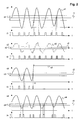
- FIG. 2 shows a curve s1 along a horizontal time axis t first size, a first reference value r1, a first tolerance range dl and a course f1 of a first flag, a course s2 of a second variable, a second reference value r2, a second tolerance range d2 and a second flag f2, a curve s3 of a third variable, a third reference value r3, a third tolerance range d3 and a third flag f3, and a curve s4 of a fourth variable, a fourth reference value r4, one fourth tolerance range d4 and a fourth flag f4.
- the first or second Flags f1, f2 are then only in the manner described above Set value one if the first or second quantity sl, s2 is within of the first or second tolerance range d1, d2 around the first respectively second reference value r1, r2.
- the first variable has a continuous course s1 of its values
- the second size has discrete values s2.
- the first and second sizes correspond for example, an input variable 2 or an output variable 3 of a functioning analog-digital converter 1.
- the Output size of the converter 1 digitally coded.
- the converter 1 is an analog amplifier and correspond to functioning converter 1 the curves of the input variable 2 and the output variable 3 both approximate the course of the first size.
- the converter 1 is a digital-to-analog converter and correspond to the curves of the input variable when converter 1 is functioning 2 and the initial size 3 both approximate the course of the second Size.
- the reference values 41, 61 are obtained by comparing the converter 1, for example during commissioning. If converter 1 is on If the analog-to-digital converter is used, input variable 2 will be the default value preferably a value of zero is applied, for example an earth potential or a zero current. As the input reference value 41, at which the input detector 4 responds, a value of zero is also defined. Because of a Offsets of converter 1 result in a specific value of the output variable 3, which is generally different from zero. This value of the output quantity 3 is selected as the output reference value 61 at which the output detector 6 appeals. The output reference value 61 corresponds to that Input reference value 41 zero. If converter 1 is a digital-to-analog converter input variable 2 is varied until output variable 3 has a value Has zero.
- the corresponding value of input variable 2 is called the input reference value 41 selected and assigned an output reference value 61 zero.
- a comparison takes place, which instead of one Earth potential is a supply voltage or a nominal voltage of a System used as the reference value of an analog side of a converter 1.
- FIG. 3 shows a preferred variant of the invention: a monitoring device 10 has a converter 1, an output detector 6 and a digital unit 12 on.
- the converter 1 is a digital-to-analog converter, which is the input variable 2 received by the digital unit 12 in digitally coded form.
- the Digital unit 12 receives input variable 2 via an input, not shown transmitted, or generates the input variable 2 itself.
- the output detector 6 is an analog component, which is the output flag 7 or analog flag transmitted to the digital unit 12. The analog flag shows a match the output variable 3 with the output reference value 61.
- the Digital unit 12 has a programmable computing unit such as a microprocessor or an ASIC (Application-Specific Integrated Circuit) or FPGA (Field Programmable Gate Array) and / or a specially designed digital Circuit on.
- the functions of the input detector described above 4 and the evaluation unit 8 are realized in the digital unit 12.
- the digital flag is preferably by an internal variable or an internal signal the digital unit 12 realized.
- FIG. 4 shows a further preferred variant of the invention.
- a monitoring device 10 has a converter 1, an input detector 4 and a digital unit 12.
- the converter 1 is an analog-digital converter that the output variable 3 in digitally coded form to a digital unit 12 transmitted.
- the digital unit 12 transmits the output variable 3 via a output not shown and / or processed itself.
- the input detector 4 is an analog component, which is the input flag 5 or analog flag transmitted to the digital unit 12.
- the analog flag shows a match of input variable 2 with input reference value 41.
- the Digital unit 12 has a programmable computing unit such as a microprocessor or an ASIC or FPGA and / or a specially designed one digital circuit on.
- the functions of the output detector described above 6 and the evaluation unit 8 are implemented in the digital unit 12. For this purpose it forms a digital flag, which corresponds to the output size 3 with the output reference value 61.
- the digital flag is preferably by an internal variable or an internal signal of the Digital unit 12 realized.
- FIG. 5 shows a further preferred variant of the invention. That is the converter 1 from several cascaded partial converters 1 ', 1 ", 1"', the output variables 3 ', 3 ", 3"' on output detectors 6 ', 6 ", 6"' to form Output flags 7 ', 7 ", 7”' are performed. The input flag 5 and the output flags 7 ', 7 “, 7”' are evaluated by the evaluation unit 8, which if there is a mismatch between input flag 5 and / or Output flags 7 ', 7 “, 7”' on a malfunction of a partial converter 1 ', 1 ", 1"' closes.
- the given ones correspond Reference values a zero value of a current, or a zero value of a Voltage, i.e. a ground potential, and / or a supply voltage an electrical system.
- Such reference values have the advantage that they occur anywhere in a system and are defined. If a reference value an analog quantity corresponds to an earth potential or a value of zero, so the analog detector is simply an analog comparator whose switchover threshold equal to an upper limit of the specified tolerance range around the reference value is zero. Falls below an absolute value of the analog The comparator sets the size of the upper limit of the tolerance range its output signal or analog flag to the value one and thus shows indicates that the analog quantity has the specified reference value zero.
- the method according to the invention is particularly suitable for function monitoring a converter of a control or protective device electrical switchgear.
- digital-to-analog converters 1 used to digitally transmit signals 2 from protective devices via glass fibers implement in analog signals 3. These analog signals 3 are on Analog inputs from existing older protection devices.
- a monitoring device 10 according to the invention the structure of Figure 3 used for such a digital-to-analog converter 1. Voltages are therefore preferably based on reference values Zero, which corresponds to earth potential, is monitored. Streams are also preferred monitored based on zero reference values. For a comparison monitoring a converter 1, which processes a current measurement, a corresponding line section is switched off.
- a malfunction of a converter 1, which leads to an overload of the output variable 3 of the converter 1 leads, in the case of a converter 1, which processes a current measurement, not in the short term, that is, in one Time during which a protective device must react from a short-circuit current differentiate in the plant.
- the invention allows the Detect malfunction.
- an electrical switchgear When monitoring the function of a converter 1 of a protective device an electrical switchgear is preferably used when a Malfunction of converter 1 marks output variable 3 as invalid, for example by transmitting a corresponding status signal.
- protective functions are applied to the converter 1 are switched off. This is permissible because of breakdowns in switchgear occur very rarely.
- the risk is advantageously one Malfunction due to a defective converter 1 is greater than the risk an accident that is not optimally recorded.
- the invention has the advantage that monitoring is very simple Means is feasible. For example, for a digital-to-analog converter or an analog-to-digital converter just an additional analog component needed, while the other functions in an already existing, for example programmable, digital unit 12 can be realized. Monitoring according to the invention is also retrofitted to an existing one Converter can be implemented.
Landscapes
- Engineering & Computer Science (AREA)
- Theoretical Computer Science (AREA)
- Analogue/Digital Conversion (AREA)
- Emergency Protection Circuit Devices (AREA)
Priority Applications (4)
| Application Number | Priority Date | Filing Date | Title |
|---|---|---|---|
| EP99811073A EP1102403A1 (fr) | 1999-11-19 | 1999-11-19 | Surveillance du fonctionnement d'un transformateur |
| JP2000350603A JP5068899B2 (ja) | 1999-11-19 | 2000-11-17 | コンバータの動作をモニタする装置及び方法 |
| US09/715,019 US6577987B1 (en) | 1999-11-19 | 2000-11-20 | Operational monitoring for a converter |
| US11/150,597 USRE41343E1 (en) | 1999-11-19 | 2005-06-10 | Operational monitoring for a converter |
Applications Claiming Priority (1)
| Application Number | Priority Date | Filing Date | Title |
|---|---|---|---|
| EP99811073A EP1102403A1 (fr) | 1999-11-19 | 1999-11-19 | Surveillance du fonctionnement d'un transformateur |
Publications (1)
| Publication Number | Publication Date |
|---|---|
| EP1102403A1 true EP1102403A1 (fr) | 2001-05-23 |
Family
ID=8243154
Family Applications (1)
| Application Number | Title | Priority Date | Filing Date |
|---|---|---|---|
| EP99811073A Withdrawn EP1102403A1 (fr) | 1999-11-19 | 1999-11-19 | Surveillance du fonctionnement d'un transformateur |
Country Status (3)
| Country | Link |
|---|---|
| US (2) | US6577987B1 (fr) |
| EP (1) | EP1102403A1 (fr) |
| JP (1) | JP5068899B2 (fr) |
Families Citing this family (3)
| Publication number | Priority date | Publication date | Assignee | Title |
|---|---|---|---|---|
| AU2007216691A1 (en) * | 2006-09-11 | 2008-04-03 | Universidad Tecnica Federico Santa Maria | Intelligent monitoring system and method for mill drives in mineral grinding processes |
| JP6318483B2 (ja) * | 2013-06-28 | 2018-05-09 | 株式会社デンソー | 電子装置の製造方法および限界値設定装置 |
| US9634624B2 (en) | 2014-12-24 | 2017-04-25 | Stmicroelectronics S.R.L. | Method of operating digital-to-analog processing chains, corresponding device, apparatus and computer program product |
Citations (2)
| Publication number | Priority date | Publication date | Assignee | Title |
|---|---|---|---|---|
| DD251659A1 (de) * | 1986-07-29 | 1987-11-18 | Zeiss Jena Veb Carl | Schaltungsanordnung zum pruefen und justieren von analog-digital-umsetzern |
| EP0883249A2 (fr) * | 1997-06-03 | 1998-12-09 | Leine & Linde AB | Codeur |
Family Cites Families (15)
| Publication number | Priority date | Publication date | Assignee | Title |
|---|---|---|---|---|
| DE251659C (fr) | ||||
| US3816813A (en) * | 1972-01-24 | 1974-06-11 | Spacetac Inc | Automatic converter tester |
| US4215412A (en) | 1978-07-13 | 1980-07-29 | The Boeing Company | Real time performance monitoring of gas turbine engines |
| US4266292A (en) * | 1978-11-20 | 1981-05-05 | Wescom Switching, Inc. | Method and apparatus for testing analog-to-digital and digital-to-analog code converters |
| US4419656A (en) * | 1980-11-07 | 1983-12-06 | Fairchild Camera & Instrument Corp. | Method and apparatus for digital converter testing |
| DE3614597A1 (de) * | 1986-04-30 | 1987-11-05 | Bosch Gmbh Robert | Verfahren und schaltungsanordnung zur a/d-wandlung eines gleichspannungssignals |
| JPS6489820A (en) * | 1987-09-30 | 1989-04-05 | Kawasaki Steel Co | Fault detection method in a/d converter and d/a converter |
| JPH0389717A (ja) * | 1989-09-01 | 1991-04-15 | Nec Corp | 故障検出回路 |
| DE69124709T2 (de) * | 1990-03-15 | 1997-05-28 | At & T Corp | Eingebaute Selbstprüfung für Analog-Digitalumsetzer |
| US5185607A (en) * | 1992-01-31 | 1993-02-09 | Motorola, Inc. | Method and apparatus for testing an analog to digital converter |
| US5319370A (en) * | 1992-08-31 | 1994-06-07 | Crystal Semiconductor, Inc. | Analog-to-digital converter with a continuously calibrated voltage reference |
| US5321403A (en) * | 1993-04-14 | 1994-06-14 | John Fluke Mfg. Co., Inc. | Multiple slope analog-to-digital converter |
| DE19810469A1 (de) * | 1998-03-11 | 1999-09-16 | Philips Patentverwaltung | Schaltungsanordnung zur Kontrolle einer Ausgangslast |
| JP3819589B2 (ja) * | 1998-04-30 | 2006-09-13 | 株式会社アドバンテスト | Ad変換器の評価装置 |
| US6297757B1 (en) * | 1999-02-11 | 2001-10-02 | Motorola, Inc. | Method and circuit for testing an analog-to-digital converter module on a data processing system having an intermodule bus |
-
1999
- 1999-11-19 EP EP99811073A patent/EP1102403A1/fr not_active Withdrawn
-
2000
- 2000-11-17 JP JP2000350603A patent/JP5068899B2/ja not_active Expired - Fee Related
- 2000-11-20 US US09/715,019 patent/US6577987B1/en not_active Ceased
-
2005
- 2005-06-10 US US11/150,597 patent/USRE41343E1/en not_active Expired - Lifetime
Patent Citations (2)
| Publication number | Priority date | Publication date | Assignee | Title |
|---|---|---|---|---|
| DD251659A1 (de) * | 1986-07-29 | 1987-11-18 | Zeiss Jena Veb Carl | Schaltungsanordnung zum pruefen und justieren von analog-digital-umsetzern |
| EP0883249A2 (fr) * | 1997-06-03 | 1998-12-09 | Leine & Linde AB | Codeur |
Also Published As
| Publication number | Publication date |
|---|---|
| USRE41343E1 (en) | 2010-05-18 |
| JP2001211074A (ja) | 2001-08-03 |
| JP5068899B2 (ja) | 2012-11-07 |
| US6577987B1 (en) | 2003-06-10 |
Similar Documents
| Publication | Publication Date | Title |
|---|---|---|
| DE3923432C2 (de) | Einrichtung zur Erzeugung von Meßsignalen mit einer Mehrzahl von Sensoren | |
| EP0402508A1 (fr) | Procédé et dispositif pour détecter une série d'événements anormaux dans un signal électrique, notamment dans un signal de dépolarisation du coeur | |
| DE2843810A1 (de) | Verfahren und einrichtung zur guetepruefung und ausschussanzeige beim anziehen von schraubverbindungen | |
| DE19806821A1 (de) | Gerät zur Feststellung einer Störung in einem Magnetventil | |
| DE4039521C2 (de) | Drehzahl-Spaltfehler-Detektor für Schienenfahrzeuge | |
| DE102017126754B4 (de) | Eingangsschaltung zum fehlersicheren Einlesen eines analogen Eingangssignals | |
| DE3347459C2 (fr) | ||
| DE1952349B2 (de) | Anordnung zur pruefung eines redundanten regelsystems | |
| EP0610711B1 (fr) | Dispositif électronique pour le pilotage d'un dispositif moteur électrique, en particulier un dispositif moteur pour porte de garage | |
| DE4242177A1 (de) | Schaltungsanordnung zur Überwachung einer Vielzahl von Spulen | |
| EP2169645B1 (fr) | Contrôle des lignes d'alerte d'une installation d'alerte au danger | |
| EP0524330B1 (fr) | Procédé pour l'identification et localisation de défauts des générateurs de signal dans un système d'automatisation | |
| EP1264191A2 (fr) | Dispositif et procede pour surveiller une traversee de condensateur | |
| DE102012014493B4 (de) | Verfahren und Vorrichtung zur redundanten Erkennung einer Drehrichtung | |
| WO1988005570A1 (fr) | Procede et dispositif de surveillance d'organes de commande terminaux commandes par un ordinateur | |
| DE69110546T2 (de) | Vorrichtung zur Erzeugung eines der Eingangsgrösse der Vorrichtung entsprechenden Stromes. | |
| DE19721366A1 (de) | Elektrische Schaltungsanordnung | |
| DE10037432A1 (de) | Vorrichtung und Verfahren zur Überwachung einer Kondensatordurchführung | |
| EP2169644A1 (fr) | Contrôle des lignes d'alerte d'une installation d'alerte au danger | |
| DE4403156B4 (de) | Verfahren und Vorrichtung zur Durchführung des Verfahrens zur Ansteuerung eines Verbrauchers | |
| WO2001088560A1 (fr) | Montage servant a detecter un dysfonctionnement | |
| DE69528754T2 (de) | Elektronische Vorrichtung zur Fernerkennung von Funktionsstörungen in Lampen | |
| DE4313532A1 (de) | Verfahren zur Überprüfung einer Endstufe | |
| EP0927356B1 (fr) | Procede de verification de composants electriques et dispositif permettant de mettre ledit procede en oeuvre | |
| EP1046918A2 (fr) | Procédé et circuit pour le control de sécurité d'un dispositif de pulvérisation électrostatique |
Legal Events
| Date | Code | Title | Description |
|---|---|---|---|
| PUAI | Public reference made under article 153(3) epc to a published international application that has entered the european phase |
Free format text: ORIGINAL CODE: 0009012 |
|
| AK | Designated contracting states |
Kind code of ref document: A1 Designated state(s): AT BE CH CY DE DK ES FI FR GB GR IE IT LI LU MC NL PT SE |
|
| AX | Request for extension of the european patent |
Free format text: AL;LT;LV;MK;RO;SI |
|
| 17P | Request for examination filed |
Effective date: 20011005 |
|
| AKX | Designation fees paid |
Free format text: AT BE CH CY DE DK ES FI FR GB GR IE IT LI LU MC NL PT SE |
|
| RAP1 | Party data changed (applicant data changed or rights of an application transferred) |
Owner name: ABB SCHWEIZ AG |
|
| 17Q | First examination report despatched |
Effective date: 20040524 |
|
| STAA | Information on the status of an ep patent application or granted ep patent |
Free format text: STATUS: THE APPLICATION IS DEEMED TO BE WITHDRAWN |
|
| 18D | Application deemed to be withdrawn |
Effective date: 20040602 |