EP1102680B1 - Stabilisierungssystem für veränderbaren spalt - Google Patents
Stabilisierungssystem für veränderbaren spalt Download PDFInfo
- Publication number
- EP1102680B1 EP1102680B1 EP99943651A EP99943651A EP1102680B1 EP 1102680 B1 EP1102680 B1 EP 1102680B1 EP 99943651 A EP99943651 A EP 99943651A EP 99943651 A EP99943651 A EP 99943651A EP 1102680 B1 EP1102680 B1 EP 1102680B1
- Authority
- EP
- European Patent Office
- Prior art keywords
- frame
- gap
- bearing ring
- cam
- metering roller
- Prior art date
- Legal status (The legal status is an assumption and is not a legal conclusion. Google has not performed a legal analysis and makes no representation as to the accuracy of the status listed.)
- Expired - Lifetime
Links
- 239000003381 stabilizer Substances 0.000 title description 2
- 230000000087 stabilizing effect Effects 0.000 claims description 34
- 230000001965 increasing effect Effects 0.000 claims description 8
- 230000003247 decreasing effect Effects 0.000 claims description 7
- 238000007645 offset printing Methods 0.000 description 4
- 238000007639 printing Methods 0.000 description 4
- 230000002411 adverse Effects 0.000 description 3
- 230000001627 detrimental effect Effects 0.000 description 1
- 230000000694 effects Effects 0.000 description 1
- 230000002708 enhancing effect Effects 0.000 description 1
- 238000012423 maintenance Methods 0.000 description 1
- 239000000463 material Substances 0.000 description 1
- 238000000034 method Methods 0.000 description 1
- 238000012986 modification Methods 0.000 description 1
- 230000004048 modification Effects 0.000 description 1
- 238000006467 substitution reaction Methods 0.000 description 1
Images

Classifications
-
- B—PERFORMING OPERATIONS; TRANSPORTING
- B41—PRINTING; LINING MACHINES; TYPEWRITERS; STAMPS
- B41F—PRINTING MACHINES OR PRESSES
- B41F13/00—Common details of rotary presses or machines
- B41F13/08—Cylinders
- B41F13/24—Cylinder-tripping devices; Cylinder-impression adjustments
- B41F13/26—Arrangement of cylinder bearings
- B41F13/28—Bearings mounted eccentrically of the cylinder axis
-
- B—PERFORMING OPERATIONS; TRANSPORTING
- B41—PRINTING; LINING MACHINES; TYPEWRITERS; STAMPS
- B41F—PRINTING MACHINES OR PRESSES
- B41F13/00—Common details of rotary presses or machines
- B41F13/08—Cylinders
- B41F13/20—Supports for bearings or supports for forme, offset, or impression cylinders
- B41F13/21—Bearer rings
Definitions
- the present invention relates generally to rotary offset printing presses. More specifically, the present invention relates to a variable gap adjusting device for adjusting the gap between a metering roller and a fountain roller, and for stabilizing the metering roller during press operations.
- Rotary offset printing presses typically employ a metering roller mounted closely adjacent to a fountain roller such that the rollers define a small gap between each other.
- a raised bearer ring on the fountain bears against the body of the metering roller in order to maintain a gap between the rollers.
- the present invention allows for the precise control and variable adjustment of the gap between the metering roller and the fountain roller, which maintains the desired gap size and which permits the roller position to be adjusted to accommodate ink build up during normal press operations.
- the present device also allows the gap to be adjusted to account for normal wear and tear. Fast and precise adjustment of the gap is possible, and the rollers are stabilized to prevent vibration and movement, thus enhancing performance of the printer.
- a gap adjusting device for a rotary press comprises a frame, a fountain roller rotatably mounted to the frame, and a stabilizing member mounted adjacent to the fountain roller.
- a metering roller is rotatably mounted to an eccentric member, and a gap is defined between the metering roller and the fountain roller.
- the eccentric member is pivotally mounted to the frame by a bearing ring having an outer race, and a portion of the outer race is positioned to contact the stabilizing member.
- An actuator is connected to the eccentric member for rotating the eccentric member within the bearing ring, so that upon rotation of the eccentric member the size of the gap is varied.
- the eccentric member includes a mechanical stop which is positioned to abut a portion of the frame, and the mechanical stop is provided with a locking adjustment screw or bolt in order to further secure the position of the eccentric member.
- the actuator for shifting the eccentric member is preferably an air cylinder, although a hydraulic cylinder or other mechanical actuator may also be employed.
- the bearing ring is provided with a clamp for fixing the position of the bearing ring relative to the eccentric member.
- the stabilizing member is preferably a hardened cam, which is mounted on a bearing concentric with the central axis of the fountain roller and which is rotatable about the central axis.
- the cam member abuts the outer race of the bearing ring that supports the eccentric member, and serves to stabilize the position of the metering roller relative to the fountain roller.
- the bearing ring that supports the stabilizing member preferably includes a flange having an elongated slot, thus permitting the position of the cam member to be changed by rotating the stabilizing member within its bearing ring.
- a lock nut or similar device secures the position of the cam member.
- the eccentric member is pivotally mounted within a bearing ring having an outer race, so that the eccentric member pivots about a pivot point.
- the metering roller is rotatably mounted to the eccentric member, but the central axis of the metering roller is offset from the eccentric member pivot point, so that upon rotational movement of the eccentric member, the metering roller is moved toward or away from the fountain roller, thereby decreasing or increasing, respectively, the size of the gap between the rollers.
- a gap adjusting device for a rotary press includes a fountain roller rotatably mounted to a frame, and a stabilizing member mounted adjacent to the fountain roller.
- a metering roller is rotatably supported by an adjustment member, and a gap is formed between the metering roller and the fountain roller.
- the adjustment member is supported for shiftable movement relative to the frame, and an abutment member mounted to the adjustment member is positioned to contact the stabilizing member.
- An actuator connected to the adjustment member shifts the adjustment member, thereby moving the metering roller and the fountain roller relative to each other so that the size of the gap can be varied.
- a gap adjusting device for a rotary press includes a frame, a fountain roller and a metering roller is rotatably mounted to the frame so that a gap is formed between the rollers.
- Adjustment means having an actuator is provided for shifting one of the rollers toward or away from the other roller, thereby decreasing or increasing, respectively, the size of the gap therebetween.
- Stabilizing means is provided for stabilizing the metering roller.
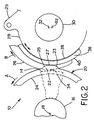
- Figure 1 shows a gap adjusting device assembled according to the teachings of the present invention which is generally referred to by the reference numeral 10 and which is adapted for use on a rotary offset printing press (not shown).
- Device 10 includes a frame 12 and a fountain roller 14 which is mounted on frame 12 by a bearing 16 for rotation about a central axis 18.
- an actuator 13 is provided so that frame 12 is adjustable with respect to other components of the rotary press (not shown).
- a stabilizing member 20 having a cam 22 is rotatably mounted on a bearing 24.
- cam 22 includes a pair of variably sloping side portions 23, 25, respectively, as well as a raised center area 27, such that the effective radius of cam 22 is less than the radius of stabilizing member 20.
- a metering roller 26 is rotatably and eccentrically mounted to an eccentric member 28 by a bearing 30 for rotation about a central axis 32.
- a gap 34 is defined between the fountain roller 14 and the metering roller 26.
- the eccentric member 28 is pivotally mounted in a bearing ring 36 having an inner race 38 and an outer race or surface 40, so that the eccentric member can pivot about a central axis 42.
- the central axis 32 of the metering roller 26 is offset from the central axis 42 of the eccentric member 28.
- Eccentric member 28 includes a lug 29, and an actuator 44 connected to lug 29 adjustably connects the eccentric member 28 to the frame 12, so that eccentric member 28 can be rotated about its central axis 42 thus enabling the gap 34 between the fountain roller 14 and the metering roller 26 to be varied by virtue of the eccentric mounting of metering roller 26 to eccentric member 28. Accordingly, the eccentric member 28, using the actuator 44, may effectively be used to make small adjustments to the size of the gap 34, or alternatively may function as a throw-off device in order to greatly increase the size of the gap 34 for maintenance and other purposes.
- actuator 44 when the actuator 44 is configured as shown, extension of the actuator 44 will cause the metering roller 26 to move away from the fountain roller 14 and increase the gap 34 as the eccentric member rotates about its central axis 42. By comparison, retraction of the actuator 44 will cause the metering roller 26 to move toward the fountain roller 14 and decrease the gap 34.
- actuator 44 is a pneumatic cylinder, although a hydraulic cylinder, a threaded rod, or any suitable mechanical linkage system may be used as an alternative.
- Eccentric member 28 includes a second lug 46 having a bore 48 extending therethrough which threadably receives an adjusting bolt 50 having a lock nut 52.
- the end of the bolt 50 is positioned to abut a lug 54 extending from the frame 12.
- Bolt 50 serves to carry some of the load experienced by actuator 44 during operation of the press, and further stabilizes the relative positions of fountain roller 14 and metering roller 26.
- the eccentric member 28 rotates in a counterclockwise direction when viewing the drawings, which pulls the end of bolt 50 away from the lug 54.
- bolt 50 must first be retracted.
- Stabilizing member 20 includes a lug or flange 56 having an arcuate slot 57, and further includes a bolt 60 or similar fastener. Stabilizing member 20 can be rotated about bearing 24 in order to adjust the position of cam 22, and bolt 60 enables the rotational position of cam 22 to be fixed. Preferably, the stabilizing member is concentric with the fountain roller 14 so that the stabilizing member also rotates about the central axis 18.
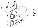
- the bearing ring 36 preferably includes a clamp 70 for fixing the position of the bearing ring 36 relative to the eccentric member 28.
- the clamp 70 includes a tab 72 on the bearing ring 36.
- the tab 72 is secured to the eccentric member 28 by a plurality of bolts 74.
- the function of the clamp 70 is as follows. Ink tends to accumulate on the outer surface 40 of the bearing ring 36 (i.e., above and below the point of contact between the cam 22 and the outer surface 40 of the bearing ring 36) during operation of the press. However, due to the contact between the cam 22 and the outer surface 40 of the bearing ring 36, no ink accumulates at this point of contact.
- the clamp 70 by preventing rotation of the bearing ring 36 during throw-off, ensures that the same contact point is maintained, which thus maintains the proper size of the gap 34 when the eccentric member 28 is thrown back to its operative position.
- fountain roller 14 and metering roller 26 are driven by a drive system (not shown) as is commonly employed in the art, so that the fountain roller 14 rotates in a counter-clockwise direction when viewing the drawings, as indicated by the reference arrow "A", while the metering roller 26 rotates in a clockwise direction when viewing the drawings, as indicated by the reference arrow “B”.
- the rollers may rotate in the direction opposite of that shown.
- Stabilizing member 20 is positioned by rotating it about the axis 18 so that the cam 22 abuts the outer race 40 of bearing ring 36.
- the available amount of rotation of stabilizing member 20 is governed by the length of arcuate slot 58, and the position is secured by tightening bolt 60. With the stabilizing member thus secured, and with cam 22 in contact with the outer race 40 of bearing ring 36, the relative position of fountain roller 14 and metering roller 26 is stabilized, subject only to the adjustment as discussed further below.
- stabilizing member 20 can be rotated upon release of the bolt 60, thereby changing the gap 34 by positioning the raised portion 27 or either of the sloping side portions 23, 25 in contact with bearing ring 36.
- the sloping side portions 23, 25 may be configured so that the range of adjustability is maximized or minimized, depending on user preferences, and may also be symmetrical or non-symmetrical with respect to the raised portion 27.
- the size of the gap 34 between the fountain roller 14 and the metering roller 26 may be set at the desired distance by extending or retracting the actuator 44.
- the size of the gap 34 is varied upon rotation of the eccentric member 28.
- the bolt 50 is retracted away from the lug 54 in order to accomplish the adjustment.
- the bolt 50 is advanced until its end abuts the lug 54, and the bolt 50 is secured in place using the lock nut 52.
- ink may build up on one or both of the rollers, thus decreasing the effective size of gap 34.
- the gap 34 can be increased or decreased by adjusting the stabilizing member 20 and/or the eccentric member 28.
Landscapes
- Engineering & Computer Science (AREA)
- Mechanical Engineering (AREA)
- Inking, Control Or Cleaning Of Printing Machines (AREA)
- Rotary Presses (AREA)
Claims (42)
- Spalteinstellvorrichtung für eine Rollen-Druckmaschine bzw. Rotationspresse, mit:einem Rahmen;einer drehbar an dem Rahmen montierten Feuchtwalze;einem an die Feuchtwalze angrenzend montierten Stabilisierelement;einer drehbar an einem exzentrischen Element montierten Dosierwalze, wobei die Dosierwalze und die Feuchtwalze dazwischen einen Spalt definieren, das exzentrische Element schwenkbar an dem Rahmen über einen Tragring montiert ist, der eine Außenlaufbahn hat, wobei ein Bereich der Außenlaufbahn derart positioniert ist, daß er das Stabilisierelement kontaktiert; undeinem Betätigungsorgan, das mit dem exzentrischen Element zum Zwecke der Drehung des exzentrischen Elementes innerhalb des Tragringes verbunden ist, so daß bei Drehung des exzentrischen Elementes die Größe des Spaltes verändert werden kann.
- Vorrichtung nach Anspruch 1, wobei das exzentrische Element einen mechanischen Stopper aufweist, wobei der mechanische Stopper derart positioniert ist, daß er einen Abschnitt des Rahmens berührt.
- Vorrichtung nach Anspruch 2, wobei der mechanische Stopper eine einstellbare Schraube mit einer Stellmutter aufweist, zum Fixieren der Drehstellung des exzentrischen Elementes.
- Vorrichtung nach Anspruch 1, wobei das Betätigungsorgan ein Luftzylinder ist.
- Vorrichtung nach Anspruch 1, wobei das Betätigungsorgan ein Luftzylinder ist und das exzentrische Element einen mechanischen Stopper mit einer Einstellschraube mit einer Stellmutter hat, wobei die Einstellschraube einen Bereich des Rahmens berührt, um die Position des exzentrischen Elementes zu fixieren.
- Vorrichtung nach Anspruch 1, wobei das Stabilisierelement in einem Tragring montiert ist und eine gehärtete Nocke bzw. Nockenscheibe aufweist, wobei die gehärtete Nocke bzw. Nockenscheibe um die Achse des Tragrings drehbar ist.
- Vorrichtung nach Anspruch 1, wobei die Dosierwalze um eine zentrale Achse dreht und das exzentrische Element um eine Lagerspitze dreht, wobei die zentrale Achse der Dosierwalze zu der Lagerspitze des exzentrischen Elementes versetzt ist.
- Vorrichtung nach Anspruch 1, wobei das Betätigungsorgan zwischen einer ausgedehnten Stellung, in welcher der Spalt vergrößert und einer zurückgezogenen Stellung, in welcher der Spalt verkleinert ist, verschiebbar ist.
- Vorrichtung nach Anspruch 6, wobei der Tragring einen gekrümmten Schlitz und eine in dem Schlitz positionierte Stellmutter aufweist zum Fixieren der Stellung der gehärteten Nocke bzw. Nockenscheibe, wobei der gekrümmte Schlitz beim Lösen der Stellmutter der gehärteten Nocke bzw. Nockenscheibe gestattet, sich außer Kontakt mit der Außenlaufbahn der Dosierwalze zu drehen.
- Spalteinstellvorrichtung für eine Rollendruckmaschine bzw. Rotationspresse, mit:einer drehbar an einem Rahmen montierten Feuchtwalze;einem an die Feuchtwalze angrenzend montierten Stabilisierelement;einer Dosierwalze, die drehbar von einem Einstellelement getragen ist, wobei die Dosierwalze und die Feuchtwalze dazwischen einen Spalt definieren, wobei das Einstellelement getragen ist zur Verschiebebewegung relativ zu dem Rahmen;ein Berührungselement, das an dem Einstellelement montiert ist, wobei ein Abschnitt des Berührelementes derart positioniert ist, daß er das Stabilisierelement kontaktiert; undeinem mit dem Einstellelement verbundenen Betätigungsorgan zum Verschieben des Einstellelementes und dabei Bewegen der Dosierwalze und der Feuchtwalze relativ zueinander, so daß die Größe des Spaltes verändert werden kann.
- Vorrichtung nach Anspruch 10, wobei das Stabilisierelement einstellbar ist.
- Vorrichtung nach Anspruch 10, wobei das Stabilisierelement an einem Tragring mit einer zentralen Achse montiert ist, wobei das Stabilisierelement um die Achse des Tragrings einstellbar ist.
- Vorrichtung nach Anspruch 10, wobei das Einstellelement einen mechanischen Stopper zur Begrenzung der Verschiebebewegung des Einstellelementes aufweist, wobei der mechanische Stopper derart positioniert ist, daß er einen Abschnitt des Rahmens berührt.
- Vorrichtung nach Anspruch 13, wobei der mechanische Stopper eine einstellbare Schraube mit einer Stellmutter aufweist zur Fixierung der Position des Einstellelementes.
- Vorrichtung nach Anspruch 10, wobei das Betätigungsorgan ein Luftzylinder ist.
- Vorrichtung nach Anspruch 10, wobei das Betätigungsorgan ein Luftzylinder ist und das Einstellelement einen mechanischen Stopper aufweist mit einer Einstellschraube mit einer Stellmutter, wobei die Einstellschraube einen Abschnitt des Rahmens berührt, zur Fixierung der Position des Einstellelementes.
- Vorrichtung nach Anspruch 10, wobei die Dosierwalze um eine zentrale Achse dreht und das Einstellelement in einem Tragring, um eine Lagerspitze drehbar, montiert ist, wobei die zentrale Achse der Dosierwalze zu der Lagerspitze des Einstellelementes versetzt ist.
- Vorrichtung nach Anspruch 10, wobei das Betätigungsorgan verschiebbar ist zwischen einer ersten Position, in welcher die Dosierwalze von der Feuchtwalze wegbewegt ist und einer zweiten Position, in welcher die Dosierwalze in Richtung der Feuchtwalze bewegt ist.
- Vorrichtung nach Anspruch 12, wobei der Tragring ein Nockenelement, einen gekrümmten Schlitz und eine in dem Schlitz positionierte Stellmutter aufweist zur Fixierung der Position des Tragrings, wobei der gekrümmte Schlitz beim Lösen der Stellmutter dem Nokkenelement gestattet, sich außer Kontakt mit dem Berührelement zu drehen.
- Vorrichtung nach Anspruch 19, wobei das Einstellelement zum Zwecke einer Schwenkbewegung von einem Tragring mit einer Außenlaufbahn getragen ist, wobei ein Abschnitt der Außenlaufbahn des Einstellelementes das Berührelement definiert.
- Spalteinstellvorrichtung für eine Rollendruckmaschine bzw. Rotationspresse mit:einem Rahmen;einer Feuchtwalze und einer drehbar an dem Rahmen montierten Dosierwalze, wobei die Feuchtwalze und die Dosierwalze dazwischen einen Spalt definieren;einem Einstellmittel mit einem Betätigungsorgan, das in eine der Rollen eingreift zwecks alternativer Bewegung der Rollen aufeinander zu und voneinander weg, um dabei jeweils die Größe des Spaltes zu vergrößern oder zu verkleinern undStabilisiermitteln zum Stabilisieren der Dosierwalze.
- Vorrichtung nach Anspruch 21, wobei das Einstellmittel ein exzentrisches Element aufweist, das schwenkbar an einem Tragring mit einer Lagerspitze und einer Außenlaufbahn montiert ist, wobei die Dosierwalze an dem exzentrischen Element montiert ist, die Achse der Dosierwalze zu der Lagerspitze versetzt ist und das Betätigungsorgan mit dem exzentrischen Element verbunden ist.
- Vorrichtung nach Anspruch 22, wobei der Tragring eine Außenlaufbahn aufweist und wobei das Stabilisierelement eine Nocke bzw. Nockenscheibe aufweist, die an der Feuchtwalze angrenzend angeordnet ist, wobei ein Abschnitt der Außenlaufbahn derart positioniert ist, daß er die Nocke bzw. Nockenscheibe kontaktiert.
- Vorrichtung nach Anspruch 21, wobei das Stabilisierelement eine konzentrisch zu der Feuchtwalze montierte, drehbare Nocke bzw. Nockenscheibe aufweist.
- Vorrichtung nach Anspruch 22, wobei das exzentrische Element einen mechanischen Stopper aufweist, wobei der mechanische Stopper derart positioniert ist, daß er einen Abschnitt des Rahmens berührt.
- Vorrichtung nach Anspruch 25, wobei der mechanische Stopper eine einstellbare Schraube mit einer Stellmutter aufweist, zur Fixierung der Drehstellung des exzentrischen Elementes.
- Vorrichtung nach Anspruch 21, wobei das Betätigungsorgan ein Luftzylinder ist.
- Vorrichtung nach Anspruch 22, wobei das Betätigungsorgan ein Luftzylinder ist und das exzentrische Element einen mechanischen Stopper mit einer Einstellschraube mit einer Stellmutter, aufweist, wobei die Einstellschraube einen Abschnitt des Rahmens berührt, um die Position des exzentrischen Elementes zu fixieren.
- Vorrichtung nach Anspruch 21, wobei das Stabilisierelement einen konzentrisch zu der Feuchtwalze montierten Tragring aufweist und ein Nockenelement hat, wobei das Nockenelement um die Achse des Tragrings drehbar ist.
- Vorrichtung nach Anspruch 22, wobei sich die Dosierwalze um eine zentrale Achse dreht und das exzentrische Element um eine Lagerspitze dreht, wobei die zentrale Achse der Dosierwalze zu der Lagerspitze des exzentrischen Elementes versetzt ist.
- Vorrichtung nach Anspruch 21, wobei das Betätigungsorgan zwischen einer verlängerten Stellung, in der der Spalt vergrößert ist, und einer zurückgezogenen Stellung, in der der Spalt verkleinert ist, verschiebbar ist.
- Vorrichtung nach Anspruch 29, wobei der Tragring einen gekrümmten Schlitz und eine in dem Schlitz positionierte Stellmutter zum Fixieren der Stellung der gehärteten Nocke bzw. Nockenscheibe aufweist, wobei es der gekrümmte Schlitz der gehärteten Nocke bzw. Nockenscheibe beim Lösen der Stellmutter gestattet, sich außer Kontakt mit der Außenlaufbahn der Dosierwalze zu drehen.
- Spalteinstellvorrichtung für eine Rollendruckmaschine bzw. Rotationspresse, mit:einem Rahmen;einer Feuchtwalze und einer Dosierwalze, die drehbar an dem Rahmen montiert ist, wobei wenigstens eine der Walzen einstellbar an dem Rahmen montiert ist, wobei die Feuchtwalze und die Dosierwalze dazwischen einen Spalt definieren, undeinem beweglichen Einstellelement, das an dem Rahmen montiert ist und betriebsmäßig in Eingriff steht mit der einen einstellbar montierten Walze zum Zwecke deren einstellbaren Bewegung, wobei die Größe des Spalts in Reaktion auf die Bewegung des Einstellelementes veränderbar ist.
- Vorrichtung nach Anspruch 33, wobei das Einstellelement drehbar an dem Rahmen montiert ist.
- Vorrichtung nach Anspruch 33, wobei das Einstellelement eine Nocke bzw. Nockenscheibe mit einem erhöhten Zentralbereich aufweist.
- Vorrichtung nach Anspruch 33, wobei das Einstellelement drehbar an einem Tragring an dem Rahmen montiert ist und eine Nocke bzw. Nockenscheibe aufweist, wobei die Nocke bzw. Nockenscheibe um eine Achse des Tragrings bewegbar ist.
- Vorrichtung nach Anspruch 35, wobei die Nocke bzw. Nockenscheibe einen erhöhten Zentralbereich aufweist, wobei der erhöhte Zentralbereich zum Teil eine erste Spaltgröße definiert.
- Vorrichtung nach Anspruch 36, wobei der Tragring einen gekrümmten Schlitz und eine in dem Schlitz positionierte Sperrbefestigung aufweist zum Fixieren der Position der Nocke bzw. Nockenscheibe, wobei der gekrümmte Schlitz beim Lösen der Sperrbefestigung eine Drehung der Nocke bzw. Nockenscheibe um die Achse des Tragrings erlaubt, wodurch die Spaltgröße durch Änderung der Stellung des erhöhten Zentralbereichs, geändert wird.
- Vorrichtung nach Anspruch 36, wobei die Nocke bzw. Nockenscheibe einen geneigten Seitenabschnitt aufweist, wobei der geneigte Seitenabschnitt eine zweite Spaltgröße definiert.
- Vorrichtung nach Anspruch 39, wobei der geneigte Abschnitt veränderbar ist und mehrere Spaltgrößen definiert.
- Vorrichtung nach Anspruch 33, wobei die Dosierwalze an einem exzentrischen Element montiert ist, wobei das exzentrische Element schwenkbar an dem Rahmen mit Hilfe eines eine Außenlaufbahn aufweisenden Tragrings montiert ist, wobei ein Abschnitt der Außenlaufbahn des exzentrischen Elementes derart positioniert ist, daß er mit dem Einstellelement in Kontakt ist.
- Spalteinstellvorrichtung für eine Rollendruckmaschine bzw. Rotationspresse, mit:einem Rahmen;einer drehbar an dem Rahmen montierten Feuchtwalze;einem an dem Rahmen montierten Einstellelement; undeiner drehbar an einem exzentrischen Element montierten Dosierwalze, wobei die Dosierwalze und die Feuchtwalze dazwischen einen Spalt definieren, wobei das exzentrische Element mit Hilfe eines eine Außenlaufbahn aufweisenden Tragrings drehbar an dem Rahmen montiert ist, wobei ein Abschnitt der Außenlaufbahn derart ausgelegt ist, daß er mit dem Einstellelement in Kontakt ist; wodurch eine Veränderung des Spaltes bei Bewegung entweder des Einstellelementes oder des exzentrischen Elementes ermöglicht ist.
Applications Claiming Priority (3)
| Application Number | Priority Date | Filing Date | Title |
|---|---|---|---|
| US128701 | 1998-08-04 | ||
| US09/128,701 US6347585B1 (en) | 1998-08-04 | 1998-08-04 | Variable gap stabilizer |
| PCT/US1999/017689 WO2000007819A1 (en) | 1998-08-04 | 1999-08-04 | Variable gap stabilizer |
Publications (2)
| Publication Number | Publication Date |
|---|---|
| EP1102680A1 EP1102680A1 (de) | 2001-05-30 |
| EP1102680B1 true EP1102680B1 (de) | 2002-10-30 |
Family
ID=22436552
Family Applications (1)
| Application Number | Title | Priority Date | Filing Date |
|---|---|---|---|
| EP99943651A Expired - Lifetime EP1102680B1 (de) | 1998-08-04 | 1999-08-04 | Stabilisierungssystem für veränderbaren spalt |
Country Status (7)
| Country | Link |
|---|---|
| US (1) | US6347585B1 (de) |
| EP (1) | EP1102680B1 (de) |
| JP (1) | JP4361692B2 (de) |
| CN (1) | CN1119243C (de) |
| AU (1) | AU5670499A (de) |
| DE (1) | DE69903738T2 (de) |
| WO (1) | WO2000007819A1 (de) |
Families Citing this family (20)
| Publication number | Priority date | Publication date | Assignee | Title |
|---|---|---|---|---|
| JP4611493B2 (ja) * | 2000-06-23 | 2011-01-12 | 株式会社小森コーポレーション | 輪転印刷機の胴装置 |
| US6756146B2 (en) | 2002-04-03 | 2004-06-29 | 3M Innovative Properties Company | Apparatus and method for automatically stacking fuel cell material layers |
| US20030188616A1 (en) * | 2002-04-03 | 2003-10-09 | Behymer Lance E. | Compliant cutting die apparatus for cutting fuel cell material layers |
| US20030188615A1 (en) * | 2002-04-03 | 2003-10-09 | 3M Innovative Properties Company | Angled product transfer conveyor |
| US6733912B2 (en) | 2002-04-03 | 2004-05-11 | 3M Innovative Properties Company | Fixture pallet apparatus for automated assembly of fuel cell material layers |
| US6749713B2 (en) * | 2002-04-03 | 2004-06-15 | 3M Innovative Properties Company | Apparatus and method for separating a fuel cell assembly from a bonding fixture |
| US6868890B2 (en) * | 2002-04-03 | 2005-03-22 | 3M Innovative Properties Company | Method and apparatus for peeling a thin film from a liner |
| US6780276B2 (en) | 2002-04-03 | 2004-08-24 | 3M Innovative Properties Company | Gap adjuster for laminating rolls |
| US7432009B2 (en) | 2002-04-03 | 2008-10-07 | 3M Innovative Properties Company | Lamination apparatus and methods |
| US6740131B2 (en) * | 2002-04-03 | 2004-05-25 | 3M Innovative Properties Company | Apparatus for automatically fabricating fuel cell |
| US20030190226A1 (en) * | 2002-04-03 | 2003-10-09 | 3M Innovative Properties Company | Apparatus and method for singulating porous fuel cell layers using adhesive tape pick head |
| US7195690B2 (en) | 2003-05-28 | 2007-03-27 | 3M Innovative Properties Company | Roll-good fuel cell fabrication processes, equipment, and articles produced from same |
| JP2005022106A (ja) * | 2003-06-30 | 2005-01-27 | Komori Corp | ローラの支持装置 |
| JP5022902B2 (ja) | 2004-09-16 | 2012-09-12 | サザン イノヴェーション インターナショナル プロプライアトリー リミテッド | 検出器出力データ内の個別信号分離装置および方法 |
| FR2895310B1 (fr) * | 2005-12-23 | 2009-04-17 | Goss Int Montataire Sa | Dispositif d'encrage et procede d'ajustement correspondant |
| DE102008046792A1 (de) * | 2007-09-20 | 2009-04-02 | Heidelberger Druckmaschinen Ag | Druckmaschine mit Schmitzringen |
| DE102009055655A1 (de) * | 2009-11-24 | 2011-05-26 | Schaeffler Technologies Gmbh & Co. Kg | Exzenterverstellung an Lagern von Druckmaschinen |
| JP2013015549A (ja) * | 2011-06-30 | 2013-01-24 | Ricoh Co Ltd | 定着装置及び画像形成装置 |
| CN103182869B (zh) * | 2011-12-31 | 2016-06-29 | 贵州中烟工业有限责任公司 | 铝箔纸打印装置 |
| CN106694307A (zh) * | 2016-12-06 | 2017-05-24 | 中山市金田机电有限公司 | 一种无溶剂复合机的定量辊微调机构及微调方法 |
Family Cites Families (22)
| Publication number | Priority date | Publication date | Assignee | Title |
|---|---|---|---|---|
| US3343484A (en) * | 1964-12-16 | 1967-09-26 | Harold P Dahlgren | Lithographic dampener with skewed metering roller |
| US3448686A (en) | 1966-12-05 | 1969-06-10 | Miehle Goss Dexter Inc | Form roller setting and control means |
| US3691956A (en) * | 1970-11-20 | 1972-09-19 | North American Rockwell | Flat adjusting and throw-off arrangement for form roller in printing press |
| US3769909A (en) * | 1971-03-10 | 1973-11-06 | Rockwell International Corp | Wet nip dampener |
| DE2143998B1 (de) | 1971-09-02 | 1973-01-04 | Maschinenfabrik Augsburg-Nürnberg AG, 8900 Augsburg | Einrichtung an einem heberlosen feuchtwerk fuer rotations-offsetdruckmaschinen zum an-, ab- und einstellen der duktorwalze |
| US3732814A (en) | 1971-12-15 | 1973-05-15 | Rockwell International Corp | Bearer arrangement for offset printing press |
| DE2338743C2 (de) | 1973-07-31 | 1975-07-24 | Heidelberger Druckmaschinen Ag, 6900 Heidelberg | Schaltwerk einer Duktorwalze eines Feucht- oder Farbwerkes einer Druckmaschine |
| DE2845932A1 (de) | 1978-10-21 | 1980-04-24 | Heidelberger Druckmasch Ag | Kombiniertes feucht-farbwerk fuer offsetdruckwerke |
| US4214527A (en) * | 1979-01-03 | 1980-07-29 | Kormori Printing Machinery Co., Ltd. | Mounting arrangement for a plate cylinder and form rollers |
| US4290359A (en) * | 1979-01-22 | 1981-09-22 | Butler Greenwich Inc. | Dampening assembly |
| DE3207622C2 (de) * | 1982-03-03 | 1985-02-21 | M.A.N.- Roland Druckmaschinen AG, 6050 Offenbach | Vorrichtung zum An-, Ab- und Einstellen von Auftragwalzen am Plattenzylinder von Druckmaschinen |
| DD210535A3 (de) | 1982-06-02 | 1984-06-13 | Polygraph Leipzig | Vorrichtung zum verstellen von farb- oder feuchtmittelauftragwalzen |
| IT1214887B (it) | 1985-12-04 | 1990-01-18 | Ghisalberti Luigi | Unita' stampante reversibile per macchine off-set conglobante dispositivi per la bagnatura e verniciatura. |
| DE3623590A1 (de) * | 1986-07-12 | 1988-02-04 | Miller Johannisberg Druckmasch | Filmfeuchtwerk fuer offsetdruckmaschinen |
| JPH0741707B2 (ja) * | 1988-05-06 | 1995-05-10 | リョービ株式会社 | 操作レバーを有するオフセット印刷機 |
| JPH0717049B2 (ja) * | 1988-05-13 | 1995-03-01 | リョービ株式会社 | オフセット印刷機におけるローラの接続・分離装置 |
| JPH01166528U (de) * | 1988-05-16 | 1989-11-22 | ||
| DE3923350C1 (de) * | 1989-07-14 | 1990-05-17 | Man Roland Druckmaschinen Ag, 6050 Offenbach, De | |
| JP2938491B2 (ja) * | 1990-01-10 | 1999-08-23 | 株式会社小森コーポレーション | 印刷機のインキ装置 |
| US5179898A (en) | 1991-11-15 | 1993-01-19 | Rockwell International Corporation | Printer with roller mounting assembly |
| US5186100A (en) * | 1992-01-16 | 1993-02-16 | Sequa Corporation | Interchangeable inker having enclosed transmission |
| DE4401300A1 (de) | 1993-02-09 | 1994-08-11 | Grapha Holding Ag | Vorrichtung zur Verarbeitung von band- resp. blattförmigem Material |
-
1998
- 1998-08-04 US US09/128,701 patent/US6347585B1/en not_active Expired - Fee Related
-
1999
- 1999-08-04 CN CN99809345A patent/CN1119243C/zh not_active Expired - Fee Related
- 1999-08-04 JP JP2000563472A patent/JP4361692B2/ja not_active Expired - Fee Related
- 1999-08-04 WO PCT/US1999/017689 patent/WO2000007819A1/en not_active Ceased
- 1999-08-04 DE DE69903738T patent/DE69903738T2/de not_active Expired - Lifetime
- 1999-08-04 AU AU56704/99A patent/AU5670499A/en not_active Abandoned
- 1999-08-04 EP EP99943651A patent/EP1102680B1/de not_active Expired - Lifetime
Also Published As
| Publication number | Publication date |
|---|---|
| US6347585B1 (en) | 2002-02-19 |
| DE69903738T2 (de) | 2003-03-20 |
| AU5670499A (en) | 2000-02-28 |
| CN1311737A (zh) | 2001-09-05 |
| JP2002522260A (ja) | 2002-07-23 |
| EP1102680A1 (de) | 2001-05-30 |
| DE69903738D1 (de) | 2002-12-05 |
| JP4361692B2 (ja) | 2009-11-11 |
| WO2000007819A9 (en) | 2001-12-06 |
| CN1119243C (zh) | 2003-08-27 |
| WO2000007819A1 (en) | 2000-02-17 |
Similar Documents
| Publication | Publication Date | Title |
|---|---|---|
| US6347585B1 (en) | Variable gap stabilizer | |
| US4458591A (en) | Rotary printing press | |
| US3448686A (en) | Form roller setting and control means | |
| CA1311149C (en) | Film dampener unit for offset printing presses | |
| EP0466420B1 (de) | Beschichtungsvorrichtung | |
| JP2868436B2 (ja) | チャンバドクター | |
| JPH0747323A (ja) | 原料ウエブへのコーティング剤展延装置 | |
| JPH0323343B2 (de) | ||
| US5020432A (en) | Device for metering ink in offset printing presses | |
| US4214527A (en) | Mounting arrangement for a plate cylinder and form rollers | |
| JPH06226953A (ja) | 印刷媒体の膨張を補整する組版修正装置 | |
| JPH11348239A (ja) | ロ―ラを設定する半自動的な装置及び方法 | |
| GB2259055A (en) | Device for adjusting forme rollers at the plate cylinder of a rotary printing machine | |
| JPH0790637B2 (ja) | オフセット印刷機又は凸板印刷機のためのインキつぼ | |
| US5676057A (en) | Device for mounting a roller in a printing machine | |
| JP3095976B2 (ja) | 印刷機の移しローラ式インキ装置においてインキを供給するための方法 | |
| EP0546029B1 (de) | Offsetdruckmaschine | |
| US3453955A (en) | Shock absorber with movement limiting stop for rotary printing press cylinders | |
| CA2096758C (en) | Device for the fastening and positional changing of a cylinder covering | |
| US5024432A (en) | Sheet transfer device for a printing machine | |
| EP0431473B1 (de) | Papierführungsvorrichtung | |
| US5862755A (en) | Rotary printing-machine cylinder having a variable outer diameter | |
| US3453956A (en) | Shock absorber for rotary printing press cylinders | |
| GB2095179A (en) | Ink fountain devices for printing press | |
| US5709149A (en) | Apparatus for tensioning printing plates on a cylinder of a rotary printing machine |
Legal Events
| Date | Code | Title | Description |
|---|---|---|---|
| PUAI | Public reference made under article 153(3) epc to a published international application that has entered the european phase |
Free format text: ORIGINAL CODE: 0009012 |
|
| 17P | Request for examination filed |
Effective date: 20001229 |
|
| AK | Designated contracting states |
Kind code of ref document: A1 Designated state(s): CH DE FR GB LI |
|
| GRAG | Despatch of communication of intention to grant |
Free format text: ORIGINAL CODE: EPIDOS AGRA |
|
| GRAG | Despatch of communication of intention to grant |
Free format text: ORIGINAL CODE: EPIDOS AGRA |
|
| 17Q | First examination report despatched |
Effective date: 20020116 |
|
| GRAG | Despatch of communication of intention to grant |
Free format text: ORIGINAL CODE: EPIDOS AGRA |
|
| GRAH | Despatch of communication of intention to grant a patent |
Free format text: ORIGINAL CODE: EPIDOS IGRA |
|
| GRAH | Despatch of communication of intention to grant a patent |
Free format text: ORIGINAL CODE: EPIDOS IGRA |
|
| GRAA | (expected) grant |
Free format text: ORIGINAL CODE: 0009210 |
|
| AK | Designated contracting states |
Kind code of ref document: B1 Designated state(s): CH DE FR GB LI |
|
| REG | Reference to a national code |
Ref country code: GB Ref legal event code: FG4D |
|
| REG | Reference to a national code |
Ref country code: CH Ref legal event code: EP |
|
| REG | Reference to a national code |
Ref country code: CH Ref legal event code: NV Representative=s name: E. BLUM & CO. PATENTANWAELTE |
|
| REF | Corresponds to: |
Ref document number: 69903738 Country of ref document: DE Date of ref document: 20021205 |
|
| ET | Fr: translation filed | ||
| RIN2 | Information on inventor provided after grant (corrected) |
Inventor name: MILAZZO, MARK Inventor name: LEE, JOHN, M. Inventor name: BAIN, LAWRENCE, J. Inventor name: KIAMCO, ROBERT, C. |
|
| PLBE | No opposition filed within time limit |
Free format text: ORIGINAL CODE: 0009261 |
|
| STAA | Information on the status of an ep patent application or granted ep patent |
Free format text: STATUS: NO OPPOSITION FILED WITHIN TIME LIMIT |
|
| 26N | No opposition filed |
Effective date: 20030731 |
|
| REG | Reference to a national code |
Ref country code: CH Ref legal event code: PFA Owner name: GOSS GRAPHIC SYSTEMS, INC. Free format text: GOSS GRAPHIC SYSTEMS, INC.#700 OAKMONT LANE#WESTMONT, ILLINOIS 60554-5546 (US) -TRANSFER TO- GOSS GRAPHIC SYSTEMS, INC.#700 OAKMONT LANE#WESTMONT, ILLINOIS 60554-5546 (US) |
|
| REG | Reference to a national code |
Ref country code: GB Ref legal event code: 732E Free format text: REGISTERED BETWEEN 20091022 AND 20091028 |
|
| REG | Reference to a national code |
Ref country code: GB Ref legal event code: 732E Free format text: REGISTERED BETWEEN 20091029 AND 20091104 |
|
| PGFP | Annual fee paid to national office [announced via postgrant information from national office to epo] |
Ref country code: CH Payment date: 20100825 Year of fee payment: 12 |
|
| PGFP | Annual fee paid to national office [announced via postgrant information from national office to epo] |
Ref country code: FR Payment date: 20100831 Year of fee payment: 12 Ref country code: DE Payment date: 20100827 Year of fee payment: 12 |
|
| PGFP | Annual fee paid to national office [announced via postgrant information from national office to epo] |
Ref country code: GB Payment date: 20100825 Year of fee payment: 12 |
|
| REG | Reference to a national code |
Ref country code: CH Ref legal event code: PL |
|
| GBPC | Gb: european patent ceased through non-payment of renewal fee |
Effective date: 20110804 |
|
| PG25 | Lapsed in a contracting state [announced via postgrant information from national office to epo] |
Ref country code: LI Free format text: LAPSE BECAUSE OF NON-PAYMENT OF DUE FEES Effective date: 20110831 Ref country code: CH Free format text: LAPSE BECAUSE OF NON-PAYMENT OF DUE FEES Effective date: 20110831 |
|
| REG | Reference to a national code |
Ref country code: FR Ref legal event code: ST Effective date: 20120430 |
|
| REG | Reference to a national code |
Ref country code: DE Ref legal event code: R119 Ref document number: 69903738 Country of ref document: DE Effective date: 20120301 |
|
| PG25 | Lapsed in a contracting state [announced via postgrant information from national office to epo] |
Ref country code: FR Free format text: LAPSE BECAUSE OF NON-PAYMENT OF DUE FEES Effective date: 20110831 Ref country code: GB Free format text: LAPSE BECAUSE OF NON-PAYMENT OF DUE FEES Effective date: 20110804 |
|
| PG25 | Lapsed in a contracting state [announced via postgrant information from national office to epo] |
Ref country code: DE Free format text: LAPSE BECAUSE OF NON-PAYMENT OF DUE FEES Effective date: 20120301 |