EP1103183A2 - Wirk-Vorrichtung - Google Patents
Wirk-Vorrichtung Download PDFInfo
- Publication number
- EP1103183A2 EP1103183A2 EP00123999A EP00123999A EP1103183A2 EP 1103183 A2 EP1103183 A2 EP 1103183A2 EP 00123999 A EP00123999 A EP 00123999A EP 00123999 A EP00123999 A EP 00123999A EP 1103183 A2 EP1103183 A2 EP 1103183A2
- Authority
- EP
- European Patent Office
- Prior art keywords
- drum
- bearing
- lever
- housing
- knitting
- Prior art date
- Legal status (The legal status is an assumption and is not a legal conclusion. Google has not performed a legal analysis and makes no representation as to the accuracy of the status listed.)
- Withdrawn
Links
- 238000007493 shaping process Methods 0.000 title 1
- 238000009940 knitting Methods 0.000 claims description 30
- 238000005452 bending Methods 0.000 abstract description 2
- 238000004898 kneading Methods 0.000 abstract 2
- 230000015572 biosynthetic process Effects 0.000 description 1
- 210000003746 feather Anatomy 0.000 description 1
- 238000007373 indentation Methods 0.000 description 1
- 238000002372 labelling Methods 0.000 description 1
- 230000000284 resting effect Effects 0.000 description 1
Images

Classifications
-
- A—HUMAN NECESSITIES
- A21—BAKING; EDIBLE DOUGHS
- A21C—MACHINES OR EQUIPMENT FOR MAKING OR PROCESSING DOUGHS; HANDLING BAKED ARTICLES MADE FROM DOUGH
- A21C7/00—Machines which homogenise the subdivided dough by working other than by kneading
- A21C7/005—Machines which homogenise the subdivided dough by working other than by kneading the dough pieces being worked in radially disposed cavities in a rotating drum
Definitions
- the invention relates to an active device according to the preamble of Claim 1.
- the chamber drums must be in one device Product change, i.e. when changing size and / or weight of the pieces of dough to be replaced.
- the bearings are here basically screwed tight, i.e. for changing a chamber drum the screw connection must be loosened, whereupon only the chamber drum can be exchanged.
- the invention has for its object an active device of the generic type Kind of design so that a very quick and easy Exchange of the chamber drum is made possible.
- the knitting device shown in the drawing has a housing 1 on which is supported on the floor 2.
- Dough dividing device 3 arranged in the dough pieces 4, so-called Dough pieces, with a given volume or weight.
- Such a dough dividing device is for example from the EP 0 721 737 A (corresponding to US Pat. No. 5,897,203), to which reference is made may be.
- a knitting device is located below the dough dividing device 3 5. This has - as far as usual - a knitting drum 6, which is concentric is surrounded by a chamber drum 7.
- a knitting drum 6 which is concentric is surrounded by a chamber drum 7.
- knitting chambers 8 which are open towards the outside and towards the knitting drum 6 are formed, in which the dough pieces 4 are placed.
- the chamber drum 7 is over part of their circumference from one of the dough pieces 4 against the Knitting drum 6 pressing and falling out of the knitting chamber 8 hindering knitting band 9 wrapped around.
- the endlessly designed knitting band 9 is guided over various deflection rollers 10 and a tension roller 11 and is taken along by the all-round drivable chamber drum 7 without slippage.
- the knitting drum 6 is in the direction of a common central longitudinal axis 12 of knitting drum 6 and chamber drum 7 and in tangential Direction, i.e. in the circumferential direction relative to the chamber drum 7, that is, it can be moved in an oscillating manner, so that those located in the knitting chambers 8 on the one hand against the knitting drum 6 and on the other hand against the knitting belt 9 adjacent dough pieces 4 are knitted round.
- the dough pieces 4 lie here in relatively flat, in the surface of the knitting drum 6 knobs designed as flat indentations 13.
- Structure and mode of action such knitting devices 5 are generally known, and for example from DE-PS 11 26 333 (corresponds to US Pat. No. 3,152,039), what is referred to.
- the active drum 6 is on a drive shaft mounted on one side in the housing 1 14 overhung, by a drive motor, not shown via a gear, also not shown, in the described Way is driven oscillating.
- the chamber drum 7 is in a bearing 15 of the drive shaft 14 adjacent bearing 16 is freely rotatably mounted, the bearing cover 17th for the chamber drum 7 on which the chamber drum 7 carries a Centering collar 18 is held concentrically to the axis 12.
- This bearing cover 19 is mounted, which rotates freely in a bearing 20 Bearing pin 21 is supported.
- This bearing cover 19 also has one Centering collar 22 on which the chamber drum 7 concentric with the axis 12 is held. The chamber drum 7 is therefore not flying, but rather stored at both ends.
- the bearing cover 19 is on the journal 21 set in the direction of the axis 12.
- the bearing pin 21 is on a bracket 23 on a pivotable bearing support lever 24 attached.
- This lever 24 is on the housing 1 by means of a pivot bearing pivotable about a vertical pivot axis 25 26 pivotally attached. As can be seen in particular in FIG. 1, it can be removed is double cranked.
- An upper lever arm 27 extends from the journal 21 horizontally to the swivel bearing 26. From the journal 21, a cranked lever section 28 extends downward and from here a lower lever arm 29 also horizontal and opposite to upper lever arm 27.
- the lever arms 27 and 29 run approximately parallel to one another and the cranked lever section 28 approximately vertical to these.
- a locking device 31 provided which attached one at the free end of the lever arm 29 pawl-like operating handle 32 with a lock bolt 33 and has a locking latch 34 attached to the housing 1.
- the free end the lever 24 can thus be firmly but easily detachably connected to the housing become, i.e. it is arranged fixed to the housing at one end in the pivot bearing 26 and can be closed by closing the locking device 31 on its other end can also be fixed to the housing. Due to the feather property it is pressed towards the knitting drum 7, so that with the lever 24 locked, the bearing cap 19 firmly against the chamber drum 7 and pressed into this and the chamber drum 7 in turn is pressed against the bearing cover 17.
- the locking device 31 released and the bearing support lever 24 together with the bearing cover 19 pivoted outward about the pivot bearing 26. Then she can only with a very small game on the drum 6 resting chamber drum 7 deducted and by another chamber drum with, for example differently shaped knitting chamber 8 to be replaced. Subsequently the lever 24 with the bearing cap 19 again in its closed position pivoted back, the bearing cover 19 with its centering collar 22 engages in the chamber drum 7. Because of the very small The centering collar engages play between chamber drum 7 and knitting drum 6 22 in the chamber drum 7; the system is self-centering.
Landscapes
- Life Sciences & Earth Sciences (AREA)
- Engineering & Computer Science (AREA)
- Food Science & Technology (AREA)
- Knitting Machines (AREA)
- Manufacturing And Processing Devices For Dough (AREA)
Abstract
Description
- Fig. 1
- eine Seitenansicht einer Wirk-Vorrichtung nach der Erfindung, entsprechend dem Sichtpfeil I in Fig. 2,
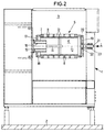
- Fig. 2
- eine Stirnansicht der Wirk-Vorrichtung gemäß dem Sichtpfeil II in Fig. 1 und
- Fig. 3
- eine Draufsicht auf einen Lager-Trag-Hebel entsprechend dem Sichtpfeil III in Fig. 2.
Claims (8)
- Wirk-Vorrichtung mitdadurch gekennzeichnet, daß eine Lagerung an einem von der Kammertrommel (7) wegschwenkbaren Lager-Trag-Hebel (24) angebracht ist undeinem Gehäuse (1),einer im Gehäuse (1) drehbar gelagerten Wirktrommel (6) undeiner die Wirktrommel (6) konzentrisch zu einer gemeinsamen Mittel-Längs-Achse (12) umgebenden Kammertrommel (7), diebeidendig in Lagerungen (16) gelagert undgegenüber den Lagerungen (16) lösbar ist,
daß der Lager-Trag-Hebel (24) mittels einer Verrriegelungs-Einrichtung (31) mit dem Gehäuse (1) lösbar verbindbar ist. - Wirk-Vorrichtung nach Anspruch 1, dadurch gekennzeichnet, daß die Kammertrommel (7) beidendig auf Lagerdeckeln (17, 19) zur Achse (12) zentriert und in Richtung der Achse (12) abziehbar gehalten ist.
- Wirk-Vorrichtung nach Anspruch 2, dadurch gekennzeichnet, daß ein Lagerdeckel (19) an dem Lager-Trag-Hebel (24) gelagert ist.
- Wirk-Vorrichtung nach einem der Ansprüche 1 bis 3, dadurch gekennzeichnet, daß der Lager-Trag-Hebel (24) an einem Ende mittels eines Schwenklagers (26) mit dem Gehäuse (1) verbunden ist und an seinem anderen Ende mittels der Verriegelungs-Einrichtung (31) lösbar mit dem Gehäuse (1) verbindbar ist.
- Wirk-Vorrichtung nach Anspruch 4, dadurch gekennzeichnet, daß die Verriegelungs-Einrichung (31) einen Betätigungsgriff (32) aufweist.
- Wirk-Vorrichtung nach einem der Ansprüche 1 bis 5, dadurch gekennzeichnet, daß der Lager-Trag-Hebel (24) in der Vertikalen biegesteif ist.
- Wirk-Vorrichtung nach einem der Ansprüche 1 bis 6, dadurch gekennzeichnet, daß der Lager-Trag-Hebel (24) in Richtung der Achse (12) federelastisch ist.
- Wirk-Vorrichtung nach einem der Ansprüche 1 bis 7, dadurch gekennzeichnet, daß der Lager-Trag-Hebel (24) abgekröpft mit einem oberen Hebelarm und einem unteren Hebelarm (29) ausgebildet ist, wobei die Schließ-Einrichtung (31) dem unteren Hebelarm (29) zugeordnet ist.
Applications Claiming Priority (2)
| Application Number | Priority Date | Filing Date | Title |
|---|---|---|---|
| DE1999155293 DE19955293B4 (de) | 1999-11-17 | 1999-11-17 | Wirk-Vorrichtung |
| DE19955293 | 1999-11-17 |
Publications (2)
| Publication Number | Publication Date |
|---|---|
| EP1103183A2 true EP1103183A2 (de) | 2001-05-30 |
| EP1103183A3 EP1103183A3 (de) | 2002-05-22 |
Family
ID=7929348
Family Applications (1)
| Application Number | Title | Priority Date | Filing Date |
|---|---|---|---|
| EP00123999A Withdrawn EP1103183A3 (de) | 1999-11-17 | 2000-11-04 | Wirk-Vorrichtung |
Country Status (2)
| Country | Link |
|---|---|
| EP (1) | EP1103183A3 (de) |
| DE (1) | DE19955293B4 (de) |
Citations (3)
| Publication number | Priority date | Publication date | Assignee | Title |
|---|---|---|---|---|
| DE1126333B (de) | 1960-02-27 | 1962-03-22 | Werner & Pfleiderer | Teigteil- und Rundwirkmaschine |
| US3152039A (en) | 1960-11-23 | 1964-10-06 | Dow Chemical Co | Germicidal compositions |
| EP0721737A2 (de) | 1995-01-13 | 1996-07-17 | Werner & Pfleiderer Lebensmitteltechnik GmbH | Teigteil- und Wirk-Maschine |
Family Cites Families (3)
| Publication number | Priority date | Publication date | Assignee | Title |
|---|---|---|---|---|
| DE3821045C1 (de) * | 1988-06-22 | 1989-04-27 | Werner & Pfleiderer Gmbh, 7000 Stuttgart, De | |
| DE4307937C2 (de) * | 1993-03-12 | 1998-04-16 | Otto Schuetz | Teigteil-Wirkmaschine |
| DE19507362C1 (de) * | 1995-03-03 | 1996-08-14 | Johann Kasper Baeckereimaschin | Teigwickelmaschine mit mindestens einer austauschbaren Walze |
-
1999
- 1999-11-17 DE DE1999155293 patent/DE19955293B4/de not_active Expired - Fee Related
-
2000
- 2000-11-04 EP EP00123999A patent/EP1103183A3/de not_active Withdrawn
Patent Citations (4)
| Publication number | Priority date | Publication date | Assignee | Title |
|---|---|---|---|---|
| DE1126333B (de) | 1960-02-27 | 1962-03-22 | Werner & Pfleiderer | Teigteil- und Rundwirkmaschine |
| US3152039A (en) | 1960-11-23 | 1964-10-06 | Dow Chemical Co | Germicidal compositions |
| EP0721737A2 (de) | 1995-01-13 | 1996-07-17 | Werner & Pfleiderer Lebensmitteltechnik GmbH | Teigteil- und Wirk-Maschine |
| US5897203A (en) | 1995-01-13 | 1999-04-27 | Werner & Pfleiderer Lebensmitteltechnik Gmbh | Dough portioning and kneading machine |
Also Published As
| Publication number | Publication date |
|---|---|
| DE19955293B4 (de) | 2008-11-13 |
| EP1103183A3 (de) | 2002-05-22 |
| DE19955293A1 (de) | 2001-05-23 |
Similar Documents
| Publication | Publication Date | Title |
|---|---|---|
| DE2742719C2 (de) | Trimmfahrrad | |
| DE1818034C3 (de) | Offen-End-Spinnmaschine | |
| EP0316553B1 (de) | Antrieb für einen Drehteller in einer Etikettiermaschine für Flaschen | |
| DE2343994C2 (de) | Fadenspeicher- und -liefervorrichtung | |
| EP0849078A1 (de) | Vorrichtung zur Vermeidung von Spiel zwischen den kämmenden Zähnen eines ersten und eines zweiten Zahnrads in einem Druckwerk einer offset-Rotationsdruckmaschine | |
| DE1510339C3 (de) | Vorrichtung zum Ablegen von Faserlunten in stillstehende Kannen | |
| DE3427259C2 (de) | Rolltor - Antrieb | |
| DE2908159C2 (de) | ||
| EP1103183A2 (de) | Wirk-Vorrichtung | |
| DE2806619C2 (de) | Heuerntemaschine, insb. zum Schwaden | |
| DE1650903B2 (de) | Zahnraederwechselgetriebe | |
| EP0272607B1 (de) | Filmschaltwerk für eine Laufbild-Filmaufnahmekamera | |
| DE2856560C2 (de) | ||
| DE3130314C2 (de) | ||
| DE1457945A1 (de) | Erntemaschine fuer halmfoermiges Gut | |
| DE60302667T2 (de) | Heumaschine | |
| DE3831890C2 (de) | ||
| DE745182C (de) | Warenabzugsvorrichtung fuer Strickmaschinen | |
| DE10234770B3 (de) | Vorrichtung zur Erzeugung von Hohlformen aus Lebensmittelmassen | |
| DE19503259C2 (de) | Drehbürstenfeger mit Kehrwalze mit Längsschlitz | |
| DE69115780T2 (de) | Vorrichtung zur Entfernung von Fasern und textilem Flug | |
| EP0516934B1 (de) | Häckseleinrichtung | |
| DE1152669B (de) | Gelenk zur loesbaren Verbindung von Webeschaeften mit dem Antriebsgestaenge des Webstuhles | |
| AT409755B (de) | Fahrrad mit kettenantrieb | |
| AT9213U1 (de) | Antrieb, insbesondere für ein einrad |
Legal Events
| Date | Code | Title | Description |
|---|---|---|---|
| PUAI | Public reference made under article 153(3) epc to a published international application that has entered the european phase |
Free format text: ORIGINAL CODE: 0009012 |
|
| AK | Designated contracting states |
Kind code of ref document: A2 Designated state(s): AT BE CH CY DE DK ES FI FR GB GR IE IT LI LU MC NL PT SE TR |
|
| AX | Request for extension of the european patent |
Free format text: AL;LT;LV;MK;RO;SI |
|
| PUAL | Search report despatched |
Free format text: ORIGINAL CODE: 0009013 |
|
| AX | Request for extension of the european patent |
Free format text: AL;LT;LV;MK;RO;SI |
|
| RIC1 | Information provided on ipc code assigned before grant |
Free format text: 7A 21C 7/01 A |
|
| AKX | Designation fees paid | ||
| REG | Reference to a national code |
Ref country code: DE Ref legal event code: 8566 |
|
| STAA | Information on the status of an ep patent application or granted ep patent |
Free format text: STATUS: THE APPLICATION IS DEEMED TO BE WITHDRAWN |
|
| 18D | Application deemed to be withdrawn |
Effective date: 20021123 |