EP1103281A2 - Katheter mit Teilen verschiedener Steifheit - Google Patents
Katheter mit Teilen verschiedener Steifheit Download PDFInfo
- Publication number
- EP1103281A2 EP1103281A2 EP00125225A EP00125225A EP1103281A2 EP 1103281 A2 EP1103281 A2 EP 1103281A2 EP 00125225 A EP00125225 A EP 00125225A EP 00125225 A EP00125225 A EP 00125225A EP 1103281 A2 EP1103281 A2 EP 1103281A2
- Authority
- EP
- European Patent Office
- Prior art keywords
- proximal
- shaft
- distal end
- distal
- guide wire
- Prior art date
- Legal status (The legal status is an assumption and is not a legal conclusion. Google has not performed a legal analysis and makes no representation as to the accuracy of the status listed.)
- Withdrawn
Links
- 238000003780 insertion Methods 0.000 claims abstract description 26
- 230000037431 insertion Effects 0.000 claims abstract description 26
- 238000004891 communication Methods 0.000 claims abstract description 7
- 239000012530 fluid Substances 0.000 claims abstract description 7
- 230000003014 reinforcing effect Effects 0.000 claims description 13
- 238000011282 treatment Methods 0.000 claims description 8
- 239000007788 liquid Substances 0.000 claims description 6
- 229910052751 metal Inorganic materials 0.000 claims description 6
- 239000002184 metal Substances 0.000 claims description 6
- 238000000034 method Methods 0.000 description 10
- 239000000463 material Substances 0.000 description 9
- 208000031481 Pathologic Constriction Diseases 0.000 description 7
- -1 polyethylene Polymers 0.000 description 7
- 230000036262 stenosis Effects 0.000 description 7
- 208000037804 stenosis Diseases 0.000 description 7
- 239000004952 Polyamide Substances 0.000 description 6
- 210000004204 blood vessel Anatomy 0.000 description 6
- 229920001971 elastomer Polymers 0.000 description 6
- 239000000806 elastomer Substances 0.000 description 6
- 229920002647 polyamide Polymers 0.000 description 6
- 229920000728 polyester Polymers 0.000 description 6
- 229920000098 polyolefin Polymers 0.000 description 6
- 238000002560 therapeutic procedure Methods 0.000 description 5
- 238000010276 construction Methods 0.000 description 4
- 238000003745 diagnosis Methods 0.000 description 4
- 239000000203 mixture Substances 0.000 description 4
- 239000002861 polymer material Substances 0.000 description 4
- 229920000915 polyvinyl chloride Polymers 0.000 description 4
- 239000004800 polyvinyl chloride Substances 0.000 description 4
- 229920005989 resin Polymers 0.000 description 4
- 239000011347 resin Substances 0.000 description 4
- 229920012753 Ethylene Ionomers Polymers 0.000 description 3
- 239000004698 Polyethylene Substances 0.000 description 3
- 239000004642 Polyimide Substances 0.000 description 3
- 239000004743 Polypropylene Substances 0.000 description 3
- 238000002399 angioplasty Methods 0.000 description 3
- 229920001577 copolymer Polymers 0.000 description 3
- 239000005038 ethylene vinyl acetate Substances 0.000 description 3
- 229920002313 fluoropolymer Polymers 0.000 description 3
- 229920001200 poly(ethylene-vinyl acetate) Polymers 0.000 description 3
- 229920001083 polybutene Polymers 0.000 description 3
- 229920000573 polyethylene Polymers 0.000 description 3
- 229920001721 polyimide Polymers 0.000 description 3
- 229920001155 polypropylene Polymers 0.000 description 3
- 229920002635 polyurethane Polymers 0.000 description 3
- 239000004814 polyurethane Substances 0.000 description 3
- 229920003225 polyurethane elastomer Polymers 0.000 description 3
- 238000000071 blow moulding Methods 0.000 description 2
- 230000007704 transition Effects 0.000 description 2
- 229910001316 Ag alloy Inorganic materials 0.000 description 1
- 206010002383 Angina Pectoris Diseases 0.000 description 1
- 229910001020 Au alloy Inorganic materials 0.000 description 1
- 229910001369 Brass Inorganic materials 0.000 description 1
- 229910000575 Ir alloy Inorganic materials 0.000 description 1
- 239000004734 Polyphenylene sulfide Substances 0.000 description 1
- 229910001260 Pt alloy Inorganic materials 0.000 description 1
- 229910001080 W alloy Inorganic materials 0.000 description 1
- 239000000853 adhesive Substances 0.000 description 1
- 230000001070 adhesive effect Effects 0.000 description 1
- 229910045601 alloy Inorganic materials 0.000 description 1
- 239000000956 alloy Substances 0.000 description 1
- 229910052782 aluminium Inorganic materials 0.000 description 1
- XAGFODPZIPBFFR-UHFFFAOYSA-N aluminium Chemical compound [Al] XAGFODPZIPBFFR-UHFFFAOYSA-N 0.000 description 1
- 238000005452 bending Methods 0.000 description 1
- 230000017531 blood circulation Effects 0.000 description 1
- 239000010951 brass Substances 0.000 description 1
- 238000003486 chemical etching Methods 0.000 description 1
- 239000000470 constituent Substances 0.000 description 1
- 238000007887 coronary angioplasty Methods 0.000 description 1
- 238000005520 cutting process Methods 0.000 description 1
- 230000000916 dilatatory effect Effects 0.000 description 1
- 239000003814 drug Substances 0.000 description 1
- 238000005516 engineering process Methods 0.000 description 1
- 238000002594 fluoroscopy Methods 0.000 description 1
- 229910052737 gold Inorganic materials 0.000 description 1
- KHYBPSFKEHXSLX-UHFFFAOYSA-N iminotitanium Chemical compound [Ti]=N KHYBPSFKEHXSLX-UHFFFAOYSA-N 0.000 description 1
- 229910052741 iridium Inorganic materials 0.000 description 1
- 238000010030 laminating Methods 0.000 description 1
- 229920000126 latex Polymers 0.000 description 1
- 239000003550 marker Substances 0.000 description 1
- 208000010125 myocardial infarction Diseases 0.000 description 1
- 229910001000 nickel titanium Inorganic materials 0.000 description 1
- 229910052697 platinum Inorganic materials 0.000 description 1
- 239000004417 polycarbonate Substances 0.000 description 1
- 229920000515 polycarbonate Polymers 0.000 description 1
- 229920000139 polyethylene terephthalate Polymers 0.000 description 1
- 239000005020 polyethylene terephthalate Substances 0.000 description 1
- 229920000069 polyphenylene sulfide Polymers 0.000 description 1
- 229920002379 silicone rubber Polymers 0.000 description 1
- 239000004945 silicone rubber Substances 0.000 description 1
- 229910052709 silver Inorganic materials 0.000 description 1
- 238000003466 welding Methods 0.000 description 1
Images

Classifications
-
- A—HUMAN NECESSITIES
- A61—MEDICAL OR VETERINARY SCIENCE; HYGIENE
- A61M—DEVICES FOR INTRODUCING MEDIA INTO, OR ONTO, THE BODY; DEVICES FOR TRANSDUCING BODY MEDIA OR FOR TAKING MEDIA FROM THE BODY; DEVICES FOR PRODUCING OR ENDING SLEEP OR STUPOR
- A61M25/00—Catheters; Hollow probes
- A61M25/0043—Catheters; Hollow probes characterised by structural features
- A61M25/0054—Catheters; Hollow probes characterised by structural features with regions for increasing flexibility
-
- A—HUMAN NECESSITIES
- A61—MEDICAL OR VETERINARY SCIENCE; HYGIENE
- A61M—DEVICES FOR INTRODUCING MEDIA INTO, OR ONTO, THE BODY; DEVICES FOR TRANSDUCING BODY MEDIA OR FOR TAKING MEDIA FROM THE BODY; DEVICES FOR PRODUCING OR ENDING SLEEP OR STUPOR
- A61M25/00—Catheters; Hollow probes
- A61M25/01—Introducing, guiding, advancing, emplacing or holding catheters
- A61M2025/0183—Rapid exchange or monorail catheters
Definitions
- the present invention relates to a catheter for performing a diagnosis or a treatment of, for example, a blood vessel for carrying out various treatments and to a dilatation catheter for dilating the stenosis within the blood vessel so as to improve the blood flow on the side of the periphery of the stenosis for curing the stenosis.
- the microcatheter includes, for example, a percutaneous transluminal coronary angioplasty catheter, hereinafter referred to as a dilatation catheter, used for curing the myocardial infarction or angina pectris.
- a percutaneous transluminal coronary angioplasty catheter hereinafter referred to as a dilatation catheter, used for curing the myocardial infarction or angina pectris.
- the method of exchanging the catheter includes a method of using a long exchange guide wire.
- the long exchange guide wire is awkward because it takes time for handling the long wire and at least two operators are required.
- a "rapid exchange" type catheter used is a "rapid exchange" type catheter.
- the catheter of this type is constructed such that the distal end portion alone of the catheter tracks the guide wire.
- a rapid exchange type catheter disclosed in EP 925801A will be described.
- the catheter is constructed such that a coil assembly comprising a coil and a transition tube covering the coil is provided between a metal tube or a proximal shaft made of a material having a high strength substantially equal to that of the metal tube and a distal shaft made of a resin having a high flexibility so as to moderate a sudden change in rigidity between the proximal shaft of a high strength and the distal shaft of a high flexibility.
- An object of the present invention is provide a rapid exchange type catheter, which permits moderating a sudden change in rigidity between the proximal shaft having a high rigidity and the distal shaft having a flexibility, which is unlikely to be broken over the entire length, and which is excellent in pressure resistance.
- a dilatation catheter comprising a tubular proximal shaft having relatively high rigidity; a tubular distal shaft having rigidity lower than that of the proximal shaft; a tubular intermediate section interposed between the proximal shaft and the distal shaft for connecting liquid tightly these shafts; a hub mounted on a proximal end portion of the proximal shaft, to which a pressure applying apparatus can be attached; a balloon arranged to a distal end portion of the distal shaft so as to be in fluid communication with the distal shaft, to which pressure can be applied from the hub; and a guide wire lumen having a distal aperture positioned on a distal end side to the distal end of the balloon and a proximal aperture positioned on a proximal end side to the proximal end of the balloon and on a distal end side to the proximal shaft, wherein a distal end portion of the proximal shaft is inserted into the intermediate
- a catheter comprising a tubular proximal shaft having relatively high rigidity; a tubular distal shaft having rigidity lower than that of the proximal shaft; a tubular intermediate section interposed between the proximal shaft and the distal shaft for connecting liquid tightly these shafts; a hub mounted on a proximal end portion of the proximal shaft; a treatment device (device for therapy or diagnose, such as an ultrasonic diagnostic device, a laser, an atherectomy cutter, a medicine supply device, a radio frequency generator or an ultrasonic therapy device) arranged to a distal end portion of the distal shaft; and a guide wire lumen having a distal aperture positioned on a distal end side to the treatment device and a proximal aperture positioned on a proximal end side to the treatment device and on a distal end side to the proximal shaft, wherein a distal end portion of the proximal shaft is inserted into the
- a spiral slit is formed on the proximal shaft, and the distal end portion of the proximal shaft is inserted into the intermediate section to form an insertion portion.
- a reinforcing member on the distal end side relatively to the distal end of the proximal shaft in a manner to extend to reach at least the proximal aperture of the guide wire lumen.
- the proximal aperture of the guide wire lumen in order to permit the rigidity of the shaft to be changed gradually, it is desirable to form the proximal aperture of the guide wire lumen in the intermediate section and to make the insertion portion of the proximal shaft extend to a region in the vicinity of the proximal aperture of the guide wire lumen.
- the distance between the proximal aperture of the guide wire lumen and the distal end of the proximal shaft is at most 5 mm. Further, in view of the case where the proximal aperture extends over a predetermined length along the longitudinal direction of the catheter, it is desirable for the distance between the distal end of the proximal aperture and the distal end of the proximal shaft to be at most 5 mm.
- the catheter can exhibit a sufficient mechanical strength and a sufficient pressure resistance in the portion corresponding to the proximal aperture or the portion between the proximal aperture and the distal end of the proximal shaft even if a reinforcing member is not arranged in any of these portions. It follows that it is possible to prevent effectively the kink generation during the operation of the catheter.
- the distal end of the spiral slit is positioned on a portion within 10 mm from the distal end of the proximal shaft toward the proximal end.
- the proximal shaft having relatively high rigidity is desirable for the proximal shaft having relatively high rigidity to be formed of a metal tube.
- a spiral slit processing to the distal end portion of the proximal shaft, it is possible to employ a general technique including, for example, a laser (e.g., YAG laser) processing, a discharge processing, a chemical etching or a cutting process. It is possible to make the pitch of the spiral slit shorter on the distal end side and longer on the proximal end side so as to permit the rigidity of the resultant insertion portion of the proximal shaft to be changed moderately from the proximal end side to the distal end side.
- a laser e.g., YAG laser
- the catheter of the present invention it suffices to apply a spiral slit processing to the distal end portion of the proximal shaft. Therefore, it is possible to assemble the catheter without complicated steps.
- the insertion portion of the proximal shaft effectively prevents the kink generation.
- the pitch of the spiral slit is made shorter on the distal end side and longer on the proximal end side so as to permit the rigidity of the insertion portion of the proximal shaft to be changed moderately from the proximal end side to the distal end side. It follows that the kink generation can be prevented more effectively.
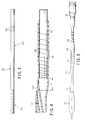
- FIG. 1 shows the appearance of a dilatation catheter 1 according to an embodiment of the present invention.
- FIG. 2 shows in a magnified fashion the major members of the dilatation catheter shown in FIG. 1, in which the proximal shaft being partly omitted.
- FIG. 3 shows the appearance of the proximal shaft.
- FIG. 4 is a cross sectional view showing the intermediate section, the distal end portion of the proximal shaft and the proximal end portion of the distal shaft.
- the dilatation catheter 1 is a so-called rapid exchange type catheter, which is inserted into a blood vessel along a guide wire 2.
- the dilatation catheter 1 comprises a hub 16, a proximal shaft 15, an intermediate section 14, a distal shaft 13, a balloon 12, and an inner tube shaft 11 arranged in this order as viewed from the proximal end.
- a lure taper is formed on the hub 16 of the proximal end side such that a pressure applying apparatus such as an inflator can be attached to the hub 16.
- the proximal shaft 15 made of a metal or a type of resin having relatively high rigidity is connected to the hub 16 so as to be in fluid communication with the hub 16.
- the proximal shaft 15 is provided with a depth marker 151, with which it can be easily detected how deep the balloon catheter 1 is inserted along a guiding catheter (not shown) during angioplasty.
- the distal end portion of the proximal shaft 15 constitutes an insertion portion 152.
- the intermediate section 14 is connected to the proximal shaft 15 on the distal end side so as to be in fluid communication with the proximal shaft 15.
- the distal shaft 13 made of a material having relatively low rigidity such as resin is connected to the intermediate section 14 on the distal end side so as to be in fluid communication with the intermediate section 14.
- the proximal end portion of the balloon 12 is connected to the distal shaft 13 on the distal end side so as to be in fluid communication with the distal shaft 13.
- An inner shaft 11 coaxially extends through the inside of the distal shaft 13 and the balloon 12.
- the distal end portion of the inner shaft 11 forms a distal end tip 111 that extends from the distal end of the balloon 12.
- the distal end tip 111 is connected liquid tightly to the balloon 12 on the distal end side.
- the proximal end portion of the inner shaft 11 extends to reach a guide wire aperture 141 formed in a portion from the intermediate section 14 to the distal shaft 13 and is bonded liquid tightly.
- the inner lumen of the inner shaft 11 extending from the distal end to reach the guide wire aperture 141 forms a guide wire lumen.
- the guide wire 2 shown in FIG. 1 is inserted through the inner shaft 11 from the distal end aperture of the distal end tip 111 serving as an inlet to the guide wire aperture 141 serving as an outlet.
- Radiopaque markers 121 are provided around the inner shaft 11 positioned inside the balloon 12.
- the balloon 12 When the balloon 12 is not inflated, the balloon 12 is folded around the outer circumference of the inner shaft 11. When the balloon 12 is inflated, the balloon 12 is formed such that the center portion becomes substantially cylindrical so as to dilate stenosis of a blood vessel easily. Incidentally, the central portion of the balloon 12 need not be made completely cylindrical. It is possible for the central portion of the balloon 12 to be made polygonal column.
- the radiopaque markers 121 are provided to facilitate the positioning of the balloon 12 at the stenosis under fluoroscopy during angioplasty.
- the dilatation catheter 1 having the aforementioned structure, when pressure is applied with a pressure applying apparatus (not shown) attached to the hub 16, a pressure medium is transmitted from the hub 16 through the proximal shaft 15, insertion portion of the proximal shaft 152, the intermediate section 14 and the clearance between the distal shaft 13 and the inner shaft 11 so as to reach the balloon 12, and thus the balloon 12 can be inflated.
- the proximal shaft 15, the intermediate section 14, the distal shaft 13, the inner shaft 11 and each of the bonded portions have resistance to pressure higher than the pressure at which the balloon 12 is ruptured.
- FIG. 3 shows in detail the structure of the proximal shaft 15.
- the proximal shaft 15 comprises a main shaft portion 153 and an insertion portion 152 prepared by applying a spiral slit processing to the distal end portion of the main shaft portion 153.
- the pitch of the spiral slit is shorter on the distal end side and is longer on the proximal end side. In other words, the pitch is gradually shortened toward the distal end.
- the insertion portion 152 is formed by applying a laser processing to the distal end portion of the main shaft portion 153.
- FIG. 4 shows the structure of the intermediate section 14, the distal end portion of the proximal shaft 15 and the proximal end portion of the distal shaft 13.
- the insertion portion 152 on the distal end portion of the proximal shaft 15 is inserted into the intermediate section 14.
- the proximal end portion of the inner shaft 11 is bonded to a part in the outer circumference of the intermediate section 14, and the proximal aperture of the inner shaft 11 is exposed to the outside of the intermediate section 14 so as to form the guide wire aperture 141.
- the insertion portion 152 is arranged inside the intermediate section 14, it is possible to make the intermediate section 14 lower in rigidity (softer) than the main shaft portion 153 and higher in rigidity (harder) than the distal shaft 13. In this manner, the rigidity of the shaft constituting the dilatation catheter 1 can be gradually changed from the proximal end portion toward the distal end portion. As a result, the stress is not concentrated on a single point when the intermediate section 14 is sharply bent, making it possible to suppress the kink generation.
- a spiral slit process is applied to the distal end portion of the proximal shaft 15 (main shaft portion 153) of the dilatation catheter 1 using a technology that is generally employed such as a laser processing so as to form the insertion portion 152 serving to prevent the kink generation. Since such a simple process can form the insertion portion 152 integral with the main shaft portion 153, it is possible to simplify the assembling process of the catheter, compared with the prior art. Also, since the insertion portion 152 is arranged inside the intermediate section 14, the stress is prevented from being concentrated on a single point when the intermediate section 14 is sharply bent, making it possible to suppress effectively the kink generation. Further, since the pitch of the spiral slit is made smaller on the distal end side and larger on the proximal end side, the rigidity of the entire shaft is changed moderately, making it possible to suppress more effectively the kink generation.
- a distance L between the guide wire aperture 141 and the distal end of the proximal shaft 15 is desirable for a distance L between the guide wire aperture 141 and the distal end of the proximal shaft 15 to be 5 mm or less.
- the distance L noted above represents the distance between the distal end of the proximal shaft 15 and the distal end of the guide wire aperture 141. If the distance L is short as in the present invention, it is possible to maintain a sufficiently high mechanical strength and pressure resistance of the catheter 1 in the portion corresponding to the guide wire aperture 141 or the portion between the guide wire aperture 141 and the distal end of the proximal shaft 15 even if another reinforcing member is not arranged in any of these portions.
- the guide wire aperture 141 it is possible to allow the guide wire aperture 141 not to extend substantially along the longitudinal direction by arranging, for example, the proximal aperture of the inner shaft 11 along the direction perpendicular to the longitudinal axis of the catheter 1.
- the guide wire aperture 141 is allowed to extend by a predetermined length along the longitudinal direction of the catheter 1 as shown in the drawing, it is possible to decrease the cross sectional area in a direction perpendicular to the longitudinal axis of the catheter 1 at the guide wire aperture 141.
- the proximal shaft 15 prefferably be made of a material having relatively high rigidity such as a Ni-Ti alloy, brass, SUS, or aluminum. It is also possible to use a resin having relatively high rigidity such as polyimide, polyvinyl chloride, or polycarbonate for forming the proximal shaft 15.
- a material having relatively high rigidity such as a Ni-Ti alloy, brass, SUS, or aluminum. It is also possible to use a resin having relatively high rigidity such as polyimide, polyvinyl chloride, or polycarbonate for forming the proximal shaft 15.
- the main shaft portion 153 of the proximal shaft 15 is formed of a tube having an outer diameter of 0.3 to 3 mm, preferably 0.5 to 1.5 mm, a wall thickness of 10 to 150 ⁇ m, preferably 20 to 100 ⁇ m, and a length of 300 to 2000 mm, preferably 700 to 1500 mm.
- the insertion portion 152 of the proximal shaft 15 is formed of a tube having an outer diameter of 0.3 to 3 mm, preferably 0.5 to 1.5 mm, a wall thickness of 10 to 150 ⁇ m, preferably 20 to 100 ⁇ m, and a length of 30 to 200 mm, preferably 50 to 180 mm.
- the distal shaft 13 and the intermediate section 14 may be formed of the same tube. Alternatively, it is possible to prepare separately the tube for the distal shaft and the tube for the intermediate section, and to join these two tubes appropriately. Further, the intermediate section 14 may be covered with another tube in order to improve the strength or pressure resistance in the portion between the guide wire aperture 141 and the distal end of the proximal shaft 15.
- the pitch of the spiral slit in the insertion portion is shorter on the distal end side and longer on the proximal end side as shown in the drawings, the pitch should be 0.1 to 10 mm, preferably 0.3 to 2 mm on the distal end side, and should be 1 to 20 mm, preferably 2 to 10 mm on the proximal end side.
- the width of the spiral slit should be not larger than 1 mm, preferably about 0.01 to 0.5 mm. It is desirable for the distal end of the spiral slit to be positioned on a portion within 10 mm from the distal end of the proximal shaft 15 toward the proximal end.
- the distal end of the slit it is more desirable for the distal end of the slit to extend to reach the distal end of the proximal shaft 15.
- the spiral slit is formed to reach a region in the vicinity of the distal end of the proximal shaft 15, the distal end portion of the proximal shaft 14 can be bent satisfactorily in the case of sharply bending the intermediate section 14, making it possible to prevent the stress from being concentrated on a single point. As a result, the kink generation can be suppressed effectively.
- the distal shaft 13 and the intermediate section 14 can be formed of polymer materials including, for example, polyolefin such as polyethylene, polypropylene, polybutene, ethylene-propylene copolymer, ethylene-vinyl acetate copolymer, ionomer, and a mixture of at least two of them, cross-linked polyolefin, polyvinyl chloride, polyamide, polyamide elastomer, polyester, polyester elastomer, polyurethane, polyurethane elastomer, fluoroplastic, and polyimide and a mixture thereof.
- the material for the intermediate section 14 should preferably be higher in rigidity than the material for the distal shaft 13.
- Each of the distal shaft 13 and the intermediate section 14 is formed of a tube having an outer diameter of 0.5 to 1.5 mm, preferably 0.7 to 1.1 mm, a wall thickness of 25 to 200 ⁇ m, preferably 50 to 100 ⁇ m, and a length of 300 to 2000 mm, preferably 300 to 1500 mm.
- the inner tube shaft 11 is formed of a material having flexibility to some extent.
- the inner tube shaft 11 is formed of polymer materials including, for example, polyolefin such as polyethylene, polypropylene, polybutene, ethylene-propylene copolymer, ethylene-vinyl acetate copolymer, ionomer, or a mixture of at least two of them, cross-linked polyolefin, polyvinyl chloride, polyamide, polyamide elastomer, polyester, polyester elastomer, polyurethane, polyurethane elastomer, polyimide and fluoroplastic and a mixture thereof.
- polyolefin such as polyethylene, polypropylene, polybutene, ethylene-propylene copolymer, ethylene-vinyl acetate copolymer, ionomer, or a mixture of at least two of them, cross-linked polyolefin, polyvinyl chloride, polyamide, polyamide elastomer, polyester
- the length of the guide wire aperture 141 in the longitudinal direction of the catheter 1 should be about 0.5 to 8 mm, preferably about 2 to 5 mm.
- the inner shaft 11 is formed of a tube having an outer diameter of about 0.1 to 1.0 mm, preferably 0.3 to 0.7 mm, a wall thickness of about 10 to 150 ⁇ m, preferably 20 to 100 ⁇ m, and a length of 100 to 2000 mm, preferably 200 to 1500 mm.
- the balloon 12 can be formed of polymer materials including, for example, polyolefin such as polyethylene, polypropylene, polybutene, ethylene-propylene copolymer, ethylene-vinyl acetate copolymer and ionomer, cross-linked polyolefin, polyester such as polyethylene terephthalate, polyester elastomer, polyvinyl chloride, polyurethane, polyurethane elastomer, polyphenylene sulfide, polyamide, polyamide elastomer, and fluoroplastic, as well silicone rubber and latex rubber.
- polyolefin such as polyethylene, polypropylene, polybutene, ethylene-propylene copolymer, ethylene-vinyl acetate copolymer and ionomer
- polyester such as polyethylene terephthalate, polyester elastomer, polyvinyl chloride, polyurethane, polyurethane elastomer, polyphenylene sulfide
- the cylindrical portion of the inflated balloon 12 is desirable for the cylindrical portion of the inflated balloon 12 to have an outer diameter of 1.0 to 10 mm, preferably 1.0 to 5.0 mm, and a length of 5 to 50 mm, preferably 10 to 40 mm. Also, it is desirable for the balloon 12 to have an entire length of 10 to 70 mm, preferably 15 to 60 mm.
- the radiopaque markers 121 it is desirable for the radiopaque markers 121 to be formed of a coil spring or a ring. It is necessary to arrange at least two or more radiopaque markers 121. It is desirable for the radiopaque markers 121 to be made of a material having a high capability of forming an X-ray image including, for example, Pt, Pt alloy, W, W alloy, Au, Au alloy, Ir, Ir alloy, Ag and Ag alloy.
- the catheter of the present invention described above is of a coaxial structure in which the guide wire lumen is coaxially arranged within the distal shaft.
- the catheter of the present invention is not limited to the particular construction. It is possible for the catheter to be constructed such that a guide wire lumen and a balloon inflation lumen are arranged in parallel within a single tube (shaft).
- FIG. 5 shows a catheter according to another embodiment of the present invention.
- a reinforcing wire 17 is arranged for reinforcing the portion between the proximal shaft having high mechanical strength and the proximal aperture of the guide wire lumen.
- the proximal end portion of the reinforcing wire 17 is fixed to the inside of the hub 16, and the reinforcing wire 17 extends within the proximal shaft and further extends from the distal end of the proximal shaft to reach a portion corresponding to the guide wire aperture.
- the reinforcing wire 17 extends from within the hub through the inner region of the proximal shaft.
- the present invention is not limited to the particular construction.
- the present invention provides a catheter, in which an insertion portion integral with the proximal shaft is formed by applying a spiral slit process to the distal end portion of the proximal shaft by a simple process such as a laser processing so as to prevent the kink occurrence in the portion having low rigidity.
- the catheter is enabled to exhibit a sufficiently high mechanical strength and a sufficiently high pressure resistance even if a reinforcing member is not arranged in the portion corresponding to the proximal aperture and in the portion between the proximal aperture and the distal end of the proximal shaft, making it possible to prevent effectively the kink occurrence during the operation of the catheter.
- the pitch of the spiral slit is made shorter on the distal end side and is made longer on the proximal end side in the present invention, making it possible to permit the rigidity to be changed moderately over the entire length of the shaft. It follows that the kink generation can be prevented more effectively.
Landscapes
- Health & Medical Sciences (AREA)
- Life Sciences & Earth Sciences (AREA)
- Biophysics (AREA)
- Pulmonology (AREA)
- Engineering & Computer Science (AREA)
- Anesthesiology (AREA)
- Biomedical Technology (AREA)
- Heart & Thoracic Surgery (AREA)
- Hematology (AREA)
- Animal Behavior & Ethology (AREA)
- General Health & Medical Sciences (AREA)
- Public Health (AREA)
- Veterinary Medicine (AREA)
- Media Introduction/Drainage Providing Device (AREA)
Applications Claiming Priority (4)
| Application Number | Priority Date | Filing Date | Title |
|---|---|---|---|
| JP33608299 | 1999-11-26 | ||
| JP33608299A JP3909991B2 (ja) | 1999-11-26 | 1999-11-26 | カテーテル |
| JP2000180450A JP2001353225A (ja) | 2000-06-15 | 2000-06-15 | カテーテル |
| JP2000180450 | 2000-06-15 |
Publications (2)
| Publication Number | Publication Date |
|---|---|
| EP1103281A2 true EP1103281A2 (de) | 2001-05-30 |
| EP1103281A3 EP1103281A3 (de) | 2002-05-02 |
Family
ID=26575353
Family Applications (1)
| Application Number | Title | Priority Date | Filing Date |
|---|---|---|---|
| EP00125225A Withdrawn EP1103281A3 (de) | 1999-11-26 | 2000-11-22 | Katheter mit Teilen verschiedener Steifheit |
Country Status (2)
| Country | Link |
|---|---|
| US (1) | US6533754B1 (de) |
| EP (1) | EP1103281A3 (de) |
Cited By (16)
| Publication number | Priority date | Publication date | Assignee | Title |
|---|---|---|---|---|
| EP1374943A1 (de) * | 2002-06-26 | 2004-01-02 | Terumo Kabushiki Kaisha | Katheter und medizinischer Schlauch |
| WO2006133960A1 (en) | 2005-06-16 | 2006-12-21 | Angiomed Gmbh & Co. Medizintechnik Kg | Catheter device |
| US7384407B2 (en) | 2001-12-03 | 2008-06-10 | Ekos Corporation | Small vessel ultrasound catheter |
| EP1340516A4 (de) * | 2000-11-09 | 2008-06-11 | Kaneka Corp | Medizinischer ballonkatheter |
| WO2008089133A1 (en) * | 2007-01-16 | 2008-07-24 | Medtronic Vascular Inc. | Proximal shaft for rapid exchange catheter |
| WO2010009399A1 (en) * | 2008-07-18 | 2010-01-21 | Boston Scientific Scimed, Inc. | Twisting bifurcation delivery system |
| US7774933B2 (en) | 2002-02-28 | 2010-08-17 | Ekos Corporation | Method of manufacturing ultrasound catheters |
| US7993308B2 (en) | 2003-04-22 | 2011-08-09 | Ekos Corporation | Ultrasound enhanced central venous catheter |
| US8323326B2 (en) | 2005-06-16 | 2012-12-04 | Angiomed GmbH & Co. Medizintechnik KG. | Catheter device |
| US8535292B2 (en) | 2008-12-03 | 2013-09-17 | C. R. Bard, Inc. | Retractable catheter |
| US8758420B2 (en) | 2005-06-16 | 2014-06-24 | Angiomed Gmbh & Co. Medizintechnik Kg | Catheter device |
| US9289576B2 (en) | 2004-06-17 | 2016-03-22 | W. L. Gore & Associates, Inc. | Catheter assembly |
| US10656025B2 (en) | 2015-06-10 | 2020-05-19 | Ekos Corporation | Ultrasound catheter |
| US10926074B2 (en) | 2001-12-03 | 2021-02-23 | Ekos Corporation | Catheter with multiple ultrasound radiating members |
| US11672553B2 (en) | 2007-06-22 | 2023-06-13 | Ekos Corporation | Method and apparatus for treatment of intracranial hemorrhages |
| US11925367B2 (en) | 2007-01-08 | 2024-03-12 | Ekos Corporation | Power parameters for ultrasonic catheter |
Families Citing this family (71)
| Publication number | Priority date | Publication date | Assignee | Title |
|---|---|---|---|---|
| DE10105592A1 (de) | 2001-02-06 | 2002-08-08 | Achim Goepferich | Platzhalter zur Arzneistofffreigabe in der Stirnhöhle |
| US6632231B2 (en) * | 2001-08-23 | 2003-10-14 | Scimed Life Systems, Inc. | Segmented balloon catheter blade |
| US7294124B2 (en) * | 2001-12-28 | 2007-11-13 | Boston Scientific Scimed, Inc. | Hypotube with improved strain relief |
| JP4441159B2 (ja) * | 2002-02-27 | 2010-03-31 | 株式会社カネカ | 血管内一時閉塞用バルーンカテーテル |
| CA2675209C (en) | 2002-03-22 | 2013-01-08 | Cordis Corporation | Rapid-exchange balloon catheter shaft and method |
| US8317816B2 (en) | 2002-09-30 | 2012-11-27 | Acclarent, Inc. | Balloon catheters and methods for treating paranasal sinuses |
| WO2004060448A2 (en) | 2003-01-03 | 2004-07-22 | Ekos Corporation | Ultrasonic catheter with axial energy field |
| US7632288B2 (en) | 2003-05-12 | 2009-12-15 | Boston Scientific Scimed, Inc. | Cutting balloon catheter with improved pushability |
| US7758604B2 (en) | 2003-05-29 | 2010-07-20 | Boston Scientific Scimed, Inc. | Cutting balloon catheter with improved balloon configuration |
| US7780626B2 (en) * | 2003-08-08 | 2010-08-24 | Boston Scientific Scimed, Inc. | Catheter shaft for regulation of inflation and deflation |
| US7887557B2 (en) * | 2003-08-14 | 2011-02-15 | Boston Scientific Scimed, Inc. | Catheter having a cutting balloon including multiple cavities or multiple channels |
| US7022104B2 (en) * | 2003-12-08 | 2006-04-04 | Angioscore, Inc. | Facilitated balloon catheter exchange |
| US20050177130A1 (en) * | 2004-02-10 | 2005-08-11 | Angioscore, Inc. | Balloon catheter with spiral folds |
| US7754047B2 (en) | 2004-04-08 | 2010-07-13 | Boston Scientific Scimed, Inc. | Cutting balloon catheter and method for blade mounting |
| US7419497B2 (en) | 2004-04-21 | 2008-09-02 | Acclarent, Inc. | Methods for treating ethmoid disease |
| US7462175B2 (en) | 2004-04-21 | 2008-12-09 | Acclarent, Inc. | Devices, systems and methods for treating disorders of the ear, nose and throat |
| US7559925B2 (en) | 2006-09-15 | 2009-07-14 | Acclarent Inc. | Methods and devices for facilitating visualization in a surgical environment |
| US9399121B2 (en) | 2004-04-21 | 2016-07-26 | Acclarent, Inc. | Systems and methods for transnasal dilation of passageways in the ear, nose or throat |
| US8764729B2 (en) | 2004-04-21 | 2014-07-01 | Acclarent, Inc. | Frontal sinus spacer |
| US7803150B2 (en) | 2004-04-21 | 2010-09-28 | Acclarent, Inc. | Devices, systems and methods useable for treating sinusitis |
| US7410480B2 (en) | 2004-04-21 | 2008-08-12 | Acclarent, Inc. | Devices and methods for delivering therapeutic substances for the treatment of sinusitis and other disorders |
| US20070208252A1 (en) | 2004-04-21 | 2007-09-06 | Acclarent, Inc. | Systems and methods for performing image guided procedures within the ear, nose, throat and paranasal sinuses |
| US9554691B2 (en) | 2004-04-21 | 2017-01-31 | Acclarent, Inc. | Endoscopic methods and devices for transnasal procedures |
| US8702626B1 (en) | 2004-04-21 | 2014-04-22 | Acclarent, Inc. | Guidewires for performing image guided procedures |
| US7566319B2 (en) | 2004-04-21 | 2009-07-28 | Boston Scientific Scimed, Inc. | Traction balloon |
| US9089258B2 (en) | 2004-04-21 | 2015-07-28 | Acclarent, Inc. | Endoscopic methods and devices for transnasal procedures |
| US9351750B2 (en) | 2004-04-21 | 2016-05-31 | Acclarent, Inc. | Devices and methods for treating maxillary sinus disease |
| US7654997B2 (en) | 2004-04-21 | 2010-02-02 | Acclarent, Inc. | Devices, systems and methods for diagnosing and treating sinusitus and other disorders of the ears, nose and/or throat |
| US8932276B1 (en) | 2004-04-21 | 2015-01-13 | Acclarent, Inc. | Shapeable guide catheters and related methods |
| US20060004323A1 (en) | 2004-04-21 | 2006-01-05 | Exploramed Nc1, Inc. | Apparatus and methods for dilating and modifying ostia of paranasal sinuses and other intranasal or paranasal structures |
| US9101384B2 (en) | 2004-04-21 | 2015-08-11 | Acclarent, Inc. | Devices, systems and methods for diagnosing and treating sinusitis and other disorders of the ears, Nose and/or throat |
| US10188413B1 (en) | 2004-04-21 | 2019-01-29 | Acclarent, Inc. | Deflectable guide catheters and related methods |
| US7361168B2 (en) * | 2004-04-21 | 2008-04-22 | Acclarent, Inc. | Implantable device and methods for delivering drugs and other substances to treat sinusitis and other disorders |
| US8864787B2 (en) | 2004-04-21 | 2014-10-21 | Acclarent, Inc. | Ethmoidotomy system and implantable spacer devices having therapeutic substance delivery capability for treatment of paranasal sinusitis |
| US8747389B2 (en) | 2004-04-21 | 2014-06-10 | Acclarent, Inc. | Systems for treating disorders of the ear, nose and throat |
| US20060063973A1 (en) | 2004-04-21 | 2006-03-23 | Acclarent, Inc. | Methods and apparatus for treating disorders of the ear, nose and throat |
| US8146400B2 (en) | 2004-04-21 | 2012-04-03 | Acclarent, Inc. | Endoscopic methods and devices for transnasal procedures |
| US20070167682A1 (en) | 2004-04-21 | 2007-07-19 | Acclarent, Inc. | Endoscopic methods and devices for transnasal procedures |
| US20190314620A1 (en) | 2004-04-21 | 2019-10-17 | Acclarent, Inc. | Apparatus and methods for dilating and modifying ostia of paranasal sinuses and other intranasal or paranasal structures |
| US8894614B2 (en) | 2004-04-21 | 2014-11-25 | Acclarent, Inc. | Devices, systems and methods useable for treating frontal sinusitis |
| US8043259B2 (en) * | 2004-05-24 | 2011-10-25 | Boston Scientific Scimed, Inc. | Medical device systems |
| US7291158B2 (en) * | 2004-11-12 | 2007-11-06 | Boston Scientific Scimed, Inc. | Cutting balloon catheter having a segmented blade |
| US8038691B2 (en) | 2004-11-12 | 2011-10-18 | Boston Scientific Scimed, Inc. | Cutting balloon catheter having flexible atherotomes |
| JP4535868B2 (ja) * | 2004-12-28 | 2010-09-01 | テルモ株式会社 | カテーテル |
| US20060184191A1 (en) * | 2005-02-11 | 2006-08-17 | Boston Scientific Scimed, Inc. | Cutting balloon catheter having increased flexibility regions |
| US8951225B2 (en) | 2005-06-10 | 2015-02-10 | Acclarent, Inc. | Catheters with non-removable guide members useable for treatment of sinusitis |
| US9445784B2 (en) * | 2005-09-22 | 2016-09-20 | Boston Scientific Scimed, Inc | Intravascular ultrasound catheter |
| US8114113B2 (en) | 2005-09-23 | 2012-02-14 | Acclarent, Inc. | Multi-conduit balloon catheter |
| US8190389B2 (en) | 2006-05-17 | 2012-05-29 | Acclarent, Inc. | Adapter for attaching electromagnetic image guidance components to a medical device |
| US9820688B2 (en) | 2006-09-15 | 2017-11-21 | Acclarent, Inc. | Sinus illumination lightwire device |
| US8439687B1 (en) | 2006-12-29 | 2013-05-14 | Acclarent, Inc. | Apparatus and method for simulated insertion and positioning of guidewares and other interventional devices |
| US8118757B2 (en) | 2007-04-30 | 2012-02-21 | Acclarent, Inc. | Methods and devices for ostium measurement |
| US8485199B2 (en) | 2007-05-08 | 2013-07-16 | Acclarent, Inc. | Methods and devices for protecting nasal turbinate during surgery |
| US10206821B2 (en) | 2007-12-20 | 2019-02-19 | Acclarent, Inc. | Eustachian tube dilation balloon with ventilation path |
| US8182432B2 (en) | 2008-03-10 | 2012-05-22 | Acclarent, Inc. | Corewire design and construction for medical devices |
| ES2700863T3 (es) | 2008-07-30 | 2019-02-19 | Acclarent Inc | Dispositivos de localización del ostium paranasal |
| AU2009293312B2 (en) | 2008-09-18 | 2015-07-09 | Acclarent, Inc. | Methods and apparatus for treating disorders of the ear nose and throat |
| WO2010081062A1 (en) * | 2009-01-12 | 2010-07-15 | Boston Scientific Scimed, Inc. | Systems and methods of making and using a coiled coolant transfer tube for a catheter of a cryoablation system |
| US9011511B2 (en) * | 2009-02-20 | 2015-04-21 | Boston Scientific Scimed, Inc. | Balloon catheter |
| US8057430B2 (en) | 2009-02-20 | 2011-11-15 | Boston Scientific Scimed, Inc. | Catheter with skived tubular member |
| US20100217374A1 (en) * | 2009-02-20 | 2010-08-26 | Boston Scientific Scimed, Inc. | Torqueable Balloon Catheter |
| US20100241155A1 (en) | 2009-03-20 | 2010-09-23 | Acclarent, Inc. | Guide system with suction |
| US7978742B1 (en) | 2010-03-24 | 2011-07-12 | Corning Incorporated | Methods for operating diode lasers |
| US8435290B2 (en) | 2009-03-31 | 2013-05-07 | Acclarent, Inc. | System and method for treatment of non-ventilating middle ear by providing a gas pathway through the nasopharynx |
| US9155492B2 (en) | 2010-09-24 | 2015-10-13 | Acclarent, Inc. | Sinus illumination lightwire device |
| US9079000B2 (en) | 2011-10-18 | 2015-07-14 | Boston Scientific Scimed, Inc. | Integrated crossing balloon catheter |
| US9433437B2 (en) | 2013-03-15 | 2016-09-06 | Acclarent, Inc. | Apparatus and method for treatment of ethmoid sinusitis |
| US9629684B2 (en) | 2013-03-15 | 2017-04-25 | Acclarent, Inc. | Apparatus and method for treatment of ethmoid sinusitis |
| US9636477B2 (en) | 2014-10-09 | 2017-05-02 | Vascular Solutions, Inc. | Catheter |
| US9782561B2 (en) | 2014-10-09 | 2017-10-10 | Vacular Solutions, Inc. | Catheter tip |
| US10238834B2 (en) | 2017-08-25 | 2019-03-26 | Teleflex Innovations S.À.R.L. | Catheter |
Citations (1)
| Publication number | Priority date | Publication date | Assignee | Title |
|---|---|---|---|---|
| EP0925801A1 (de) | 1997-12-23 | 1999-06-30 | Cordis Corporation | Ballonkatheter mit einem spiralfederförmigen Übergangsbereich |
Family Cites Families (6)
| Publication number | Priority date | Publication date | Assignee | Title |
|---|---|---|---|---|
| DE69432379T2 (de) * | 1993-01-26 | 2004-02-05 | Terumo K.K. | Einrichtung zur vasculären Dilatation und Katheter |
| WO1995024236A1 (en) | 1994-03-10 | 1995-09-14 | Schneider (Usa) Inc. | Catheter having shaft of varying stiffness |
| US5599326A (en) | 1994-12-20 | 1997-02-04 | Target Therapeutics, Inc. | Catheter with multi-layer section |
| JP3310849B2 (ja) | 1996-01-18 | 2002-08-05 | テルモ株式会社 | 血管拡張器具およびカテーテル |
| US5989218A (en) * | 1997-11-18 | 1999-11-23 | Advanced Cardiovascular Systems, Inc. | Perfusion catheter with coil supported inner tubular member |
| US6102890A (en) * | 1998-10-23 | 2000-08-15 | Scimed Life Systems, Inc. | Catheter having improved proximal shaft design |
-
2000
- 2000-11-22 EP EP00125225A patent/EP1103281A3/de not_active Withdrawn
- 2000-11-22 US US09/717,071 patent/US6533754B1/en not_active Expired - Lifetime
Patent Citations (1)
| Publication number | Priority date | Publication date | Assignee | Title |
|---|---|---|---|---|
| EP0925801A1 (de) | 1997-12-23 | 1999-06-30 | Cordis Corporation | Ballonkatheter mit einem spiralfederförmigen Übergangsbereich |
Cited By (21)
| Publication number | Priority date | Publication date | Assignee | Title |
|---|---|---|---|---|
| EP1340516A4 (de) * | 2000-11-09 | 2008-06-11 | Kaneka Corp | Medizinischer ballonkatheter |
| US10926074B2 (en) | 2001-12-03 | 2021-02-23 | Ekos Corporation | Catheter with multiple ultrasound radiating members |
| US7384407B2 (en) | 2001-12-03 | 2008-06-10 | Ekos Corporation | Small vessel ultrasound catheter |
| US7774933B2 (en) | 2002-02-28 | 2010-08-17 | Ekos Corporation | Method of manufacturing ultrasound catheters |
| US8043279B2 (en) | 2002-06-26 | 2011-10-25 | Terumo Kabushiki Kaisha | Catheter and medical tube |
| EP1374943A1 (de) * | 2002-06-26 | 2004-01-02 | Terumo Kabushiki Kaisha | Katheter und medizinischer Schlauch |
| US7993308B2 (en) | 2003-04-22 | 2011-08-09 | Ekos Corporation | Ultrasound enhanced central venous catheter |
| US9289576B2 (en) | 2004-06-17 | 2016-03-22 | W. L. Gore & Associates, Inc. | Catheter assembly |
| US8323326B2 (en) | 2005-06-16 | 2012-12-04 | Angiomed GmbH & Co. Medizintechnik KG. | Catheter device |
| US8758420B2 (en) | 2005-06-16 | 2014-06-24 | Angiomed Gmbh & Co. Medizintechnik Kg | Catheter device |
| WO2006133960A1 (en) | 2005-06-16 | 2006-12-21 | Angiomed Gmbh & Co. Medizintechnik Kg | Catheter device |
| US9615950B2 (en) | 2005-06-16 | 2017-04-11 | Angiomed Gmbh & Co. Medizintechnik Kg | Catheter device |
| US9872785B2 (en) | 2005-06-16 | 2018-01-23 | Angiomed Gmbh & Co. Medizintechnik Kg | Catheter device |
| US10596020B2 (en) | 2005-06-16 | 2020-03-24 | Angiomed Gmbh & Co. Medizintechnik Kg | Catheter device |
| US11925367B2 (en) | 2007-01-08 | 2024-03-12 | Ekos Corporation | Power parameters for ultrasonic catheter |
| WO2008089133A1 (en) * | 2007-01-16 | 2008-07-24 | Medtronic Vascular Inc. | Proximal shaft for rapid exchange catheter |
| US11672553B2 (en) | 2007-06-22 | 2023-06-13 | Ekos Corporation | Method and apparatus for treatment of intracranial hemorrhages |
| WO2010009399A1 (en) * | 2008-07-18 | 2010-01-21 | Boston Scientific Scimed, Inc. | Twisting bifurcation delivery system |
| US8535292B2 (en) | 2008-12-03 | 2013-09-17 | C. R. Bard, Inc. | Retractable catheter |
| US10656025B2 (en) | 2015-06-10 | 2020-05-19 | Ekos Corporation | Ultrasound catheter |
| US11740138B2 (en) | 2015-06-10 | 2023-08-29 | Ekos Corporation | Ultrasound catheter |
Also Published As
| Publication number | Publication date |
|---|---|
| US6533754B1 (en) | 2003-03-18 |
| EP1103281A3 (de) | 2002-05-02 |
Similar Documents
| Publication | Publication Date | Title |
|---|---|---|
| US6533754B1 (en) | Catheter | |
| JP4535868B2 (ja) | カテーテル | |
| JP2918459B2 (ja) | インターベンショナルカテーテル | |
| EP0688576B2 (de) | Vaskulärer Katheter | |
| EP2389973B1 (de) | Ballonkatheter | |
| EP1088570B1 (de) | Verstärkter Ballonkatheter | |
| JP4771456B2 (ja) | カテーテル | |
| JP5237572B2 (ja) | バルーンカテーテル及びその製造方法 | |
| JP6592892B2 (ja) | バルーンカテーテル | |
| EP0631792A1 (de) | Steuerbarer Dilatationskatheter | |
| US20050216047A1 (en) | Catheter with expandable body and method of dilating a blood vessel with such catheter | |
| JP2004024625A (ja) | カテーテルおよび医療用チューブ | |
| JP5473443B2 (ja) | カテーテル | |
| JPH02167177A (ja) | 操縦可能型拡張カテーテル | |
| JP3927735B2 (ja) | カテーテル | |
| WO2013140669A1 (ja) | バルーンカテーテル | |
| EP1104684B1 (de) | Katheter und Verfahren zur Herstellung | |
| WO2003086521A1 (en) | Dilatation catheter with stiffening wire | |
| JP2001353225A (ja) | カテーテル | |
| JP3909991B2 (ja) | カテーテル | |
| JP2002355313A (ja) | カテーテルチューブおよびバルーンカテーテル | |
| JP4833039B2 (ja) | カテーテル | |
| JP2005110721A (ja) | 拡張カテーテル | |
| JP6363922B2 (ja) | カテーテル | |
| JP4744005B2 (ja) | カテーテル |
Legal Events
| Date | Code | Title | Description |
|---|---|---|---|
| PUAI | Public reference made under article 153(3) epc to a published international application that has entered the european phase |
Free format text: ORIGINAL CODE: 0009012 |
|
| AK | Designated contracting states |
Kind code of ref document: A2 Designated state(s): AT BE CH CY DE DK ES FI FR GB GR IE IT LI LU MC NL PT SE TR |
|
| AX | Request for extension of the european patent |
Free format text: AL;LT;LV;MK;RO;SI |
|
| PUAL | Search report despatched |
Free format text: ORIGINAL CODE: 0009013 |
|
| AK | Designated contracting states |
Kind code of ref document: A3 Designated state(s): AT BE CH CY DE DK ES FI FR GB GR IE IT LI LU MC NL PT SE TR |
|
| AX | Request for extension of the european patent |
Free format text: AL;LT;LV;MK;RO;SI |
|
| 17P | Request for examination filed |
Effective date: 20020919 |
|
| AKX | Designation fees paid |
Free format text: AT BE CH CY DE DK ES FI FR GB GR IE IT LI LU MC NL PT SE TR |
|
| 17Q | First examination report despatched |
Effective date: 20030701 |
|
| STAA | Information on the status of an ep patent application or granted ep patent |
Free format text: STATUS: THE APPLICATION IS DEEMED TO BE WITHDRAWN |
|
| 18D | Application deemed to be withdrawn |
Effective date: 20031112 |