EP1103326A1 - Plaque de fermeture à tiroir - Google Patents
Plaque de fermeture à tiroir Download PDFInfo
- Publication number
- EP1103326A1 EP1103326A1 EP01201065A EP01201065A EP1103326A1 EP 1103326 A1 EP1103326 A1 EP 1103326A1 EP 01201065 A EP01201065 A EP 01201065A EP 01201065 A EP01201065 A EP 01201065A EP 1103326 A1 EP1103326 A1 EP 1103326A1
- Authority
- EP
- European Patent Office
- Prior art keywords
- plate
- indentation
- plates
- face
- slide gate
- Prior art date
- Legal status (The legal status is an assumption and is not a legal conclusion. Google has not performed a legal analysis and makes no representation as to the accuracy of the status listed.)
- Granted
Links
- 238000007373 indentation Methods 0.000 claims abstract description 63
- 238000004140 cleaning Methods 0.000 claims abstract description 6
- 230000000295 complement effect Effects 0.000 claims abstract 2
- 239000002184 metal Substances 0.000 claims description 16
- 238000000034 method Methods 0.000 claims description 14
- 230000000284 resting effect Effects 0.000 claims description 2
- 238000004064 recycling Methods 0.000 abstract description 4
- 239000011819 refractory material Substances 0.000 description 6
- 230000000694 effects Effects 0.000 description 3
- 230000012447 hatching Effects 0.000 description 3
- 238000009628 steelmaking Methods 0.000 description 3
- 229910000831 Steel Inorganic materials 0.000 description 2
- 239000010959 steel Substances 0.000 description 2
- 229910001208 Crucible steel Inorganic materials 0.000 description 1
- 238000005266 casting Methods 0.000 description 1
- 230000003628 erosive effect Effects 0.000 description 1
- 230000008595 infiltration Effects 0.000 description 1
- 238000001764 infiltration Methods 0.000 description 1
- 239000000155 melt Substances 0.000 description 1
- 238000012544 monitoring process Methods 0.000 description 1
- 230000000717 retained effect Effects 0.000 description 1
- 239000000126 substance Substances 0.000 description 1
Images

Classifications
-
- B—PERFORMING OPERATIONS; TRANSPORTING
- B22—CASTING; POWDER METALLURGY
- B22D—CASTING OF METALS; CASTING OF OTHER SUBSTANCES BY THE SAME PROCESSES OR DEVICES
- B22D41/00—Casting melt-holding vessels, e.g. ladles, tundishes, cups or the like
- B22D41/14—Closures
- B22D41/22—Closures sliding-gate type, i.e. having a fixed plate and a movable plate in sliding contact with each other for selective registry of their openings
- B22D41/28—Plates therefor
-
- Y—GENERAL TAGGING OF NEW TECHNOLOGICAL DEVELOPMENTS; GENERAL TAGGING OF CROSS-SECTIONAL TECHNOLOGIES SPANNING OVER SEVERAL SECTIONS OF THE IPC; TECHNICAL SUBJECTS COVERED BY FORMER USPC CROSS-REFERENCE ART COLLECTIONS [XRACs] AND DIGESTS
- Y10—TECHNICAL SUBJECTS COVERED BY FORMER USPC
- Y10S—TECHNICAL SUBJECTS COVERED BY FORMER USPC CROSS-REFERENCE ART COLLECTIONS [XRACs] AND DIGESTS
- Y10S266/00—Metallurgical apparatus
- Y10S266/01—Repair or restoration of apparatus
Definitions
- the present invention concerns a process for reusing slide gate plates for a metallurgical container, especially a steel making ladle. It also concerns a plate for this closure, and the closure itself.
- a slide closure To control the flow of molten steel through the bottom of a metallurgical container such as a steel making ladle, a slide closure is generally used. It involves an upper fixed refractory plate connected by a joint which is generally cemented to an internal nozzle located in the thickness of the refractory that covers the wall of the bottom of the metallurgical container, and a mobile lower plate connected to a collecting nozzle or to a jet protection tube, also through a generally cemented joint.
- a plate that has been used has damaged zones, e.g., eroded and abraded zones. Its reuse introduces risks, e.g. of the infiltration of metal between the two plates. Reuse of the plates, advantageous in the sense that it lengthens the service life of the refractories, also involves the disadvantage of introducing risks.
- the parent application proposes a process for reusing slide gate refractory plates, the closure having an upper indentation and a lower indentation for receiving a set of two refractory plates, each of these plates resting in an indentation through a face that becomes its support face and cooperating with the other plate through a face that becomes its sliding face.
- This process permits a simple management of the plates and it also permits prolonging the service life of the refractories by reducing the risks associated with this prolongation.
- a set of refractories comprised of a new plate associated with a plate that has been used only once in the slide closure, and in that during the changing of the plates, the new plate is mounted in a lower or upper loading indentation, this indentation remaining the same for each plate change, the plate used once being mounted in the other indentation (recycling).
- This process thus defines a charging indentation of new plates, always the same, and a charging indentation of plates used only once, also always the same.
- the management of the plates is simple. During a reconditioning of the slide gate the operator knows, in view of the indentation in which it was placed, which is used for the first time and which should be recycled, and which plate has been used for the second time and should be discarded.
- the operator systematically discards the recycled plate and keeps the plate that has been used once in an appropriate place so that it can be recycled. He then systematically mounts a new plate in the charging indentation, always the same, of new plates and a recycled plate in the other indentation.
- the plate used once is placed in the recycling indentation such that the face that was its support face during its first application becomes its sliding face.
- the new plate can be of interest to mount the new plate either in the upper position or in the lower one.
- the new plate is mounted as the lower plate and the reused plate is the upper plate.
- closure and regulation is always with a new plate.
- Security is optimal because the lower plate is important for the closure of the pouring orifice.
- the new plate is used as a upper plate.
- the joint between the internal nozzle and the plate is made on new surfaces.
- the present invention concerns a refractory plate designed to be mounted in an indentation of a slide closure for a metallurgical container such as a ladle or a tundish, this slide closure having an indentation for the upper plate and an indentation for the lower plate.
- the plate is characterized in that it has an aligning device that permits it to be mounted in only one position in the upper indentation, and in a single position in the lower indentation such that the support face of the plate becomes its sliding face when the plate passes from one position to the other.
- the plate is possibly ringed or has a metal envelope.
- its smaller face is at least equal to 60 % of the other face. It can have two or more tapholes.
- the invention also concerns a slide gate for a metal container that has an indentation for an upper plate and an indentation for a lower plate, characterized in that these indentations have a form such that they cannot receive an upper plate and a lower plate equipped with an aligning device except in only one position.
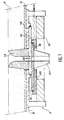
- Figure 1 shows a cross-sectional view of a slide gate for a metallurgical container such as a steel-making ladle or a distributor.
- the gate 2 is mounted under a bottom wall 4 covered with a layer of refractory material 6.
- the slide gate has a fixed underframe 8 mounted under the plate 4 and a door 10 that can be mounted to pivot relative to the fixed underframe 8.
- a fixed upper plate 12 is mounted in an indentation 14 of the upper underframe 8.
- a lower mobile plate 16 is mounted opposite the fixed plate 12.
- the plate 16 is seated in an indentation 18 of a slide 20.
- the slide 20 can be displaced in a known manner relative to the fixed part of the slide gate in order to regulate or stop the flow of molten metal.
- the upper fixed plate 12 is connected to an internal nozzle 13 that passes through the layer of refractory material 6 and has an axial channel for the passage of the molten metal.
- the mobile lower plate 16 is connected to a collecting nozzle 21.
- the two plates are symmetrically identical.
- Each of the fixed 12 and mobile 16 plates has a circular hole 22 for the passage of molten metal.
- the plates 12 and 16 are ringed. In a variant, these plates could also be surrounded by a metal envelope in a known manner, or have neither ringing nor metal envelope.
- the plates 12 and 16 have identical plane faces. These faces are not distinguished from each other when they are not mounted in the slide gate. On the other hand, when the plates have been put in place, they each have a support face with which they rest on the bottom of the indentation in which they are seated (upper indentation 14 or lower indentation 18).
- Each plate also has a sliding face, also called a working face. During pouring, these working faces makes it possible to regulate the flow of metal. They rub permanently against each other and wear rapidly. Consequently, it is necessary to change them frequently.
- a new plate is systematically mounted in the lower indentation 18 of the slide 20.
- the lower plate 16 is recovered and mounted in the indentation 14 of the upper underframe 8. It is positioned so that the face that was is working face when it was positioned in indentation 18 becomes its support face in the upper indentation 14. Reciprocally, the face that was its support face becomes its sliding or working face. This face is new in the sense that it was never used as a sliding face. The portion of it that surrounds the taphole was utilized to effect a joint with the nozzle 21, but no wear occurs on the surface in question.
- FIGs 2a, 2b and 2c illustrate the successive stages of the reutilization process according to the present invention.
- plate A is the upper plate and plate B is the lower plate before the metal is poured.
- the face of the plate A that had already been used is indicated by hatching 24. This face serves as the support face in the indentation 14 (see Figure 1).
- the other face of plate A constitutes its working face. It had never been used.
- the lower plate B is new, none of its faces have been used.
- Figure 2b shows the plates A and B after one cycle of pouring, e.g., some dozen ladles, before these plates had been replaced.
- the two faces of the upper plate A have been used, as indicated by the hatchings 24 and 26.
- Only one face of the lower plate B has been used, its upper face in the example shown, as indicated by the hatching 28.
- Plate A is discarded and plate B is mounted as the upper plate.
- a new plate C is mounted as the lower plate.
- Figure 2c which is identical to that shown in Figure 2a, with the sole exception that plate B occupies the position that was that of plate A in Figure 2a and plate C the plate that was that of plate B. The cycle thus continues in the same manner.
- a new plate is placed in the lower position.
- the lower plate undergoes a more intense erosion because it laminates or flattens the metal. This is why the upper plate is less eroded than the lower plate.
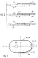
- Figure 3 shows a top view of a plate according to the present invention, which has an aligning device.
- This plate has a circling 30.
- the aligning device is comprised of a cut panel 32.
- the plate is thus asymmetric relative to each of its axes XX and YY.
- the profile of the plate in the absence of a cut panel is designated by 34.
- 14 and 18 indicate the form of the upper or lower indentation. As can be seen, this form follows the periphery of the plate at the level of the cut panel 32 so that the latter can be mounted only in a single position.
- the position of the plate in the upper indentation is different from its position in the lower indentation, such that the support face of the plate becomes its working face.
- FIG. 4 shows a cross-sectional view of a preferred mode of implementation of a plate according to the invention.
- This plate has a means for preventing the mounting more than once in one of the indentations 14 or 18 of the slide gate.
- this means is comprised of a slug 44 and a spring 42 that is capable of forcing the slug 44 out of a recess 40 provided in the thickness of the plate 12 or 16.
- the slug 40 is retained by a thermofusible substance. During the pouring of steel, under the effect of the heat of the molten metal, the plate 12 or 16 is heated and the thermofusible element melts, which frees the slug 44.
- the slug 44 then comes in contact with the indentation (the indentation 18 in the example shown on Figure 4). When the plate 16 is removed from this indentation, the slug 44 projects out completely and prevents the placement of the plate 16 in the indentation 18 a second time.
- the upper indentation 14 has a slot 46 capable of accepting the slug 44 (see Figure 5).
- the plate 16 can then be mounted without difficulty in this indentation after pivoting 180° in the a horizontal plane.
- the means that prevents mounting the plate more than once in the same indentation can be situated on the longitudinal axis XX of the plate, as in Figures 4 and 5. However, it is preferably located outside of this axis so that the plate is asymmetric relative to each of its axes XX and YY. In this manner, the means can also play the role of aligning device shown in Figure 3. For example, when the plate is new, it projects out so as to penetrate into a shallow recess in the lower indentation. After an initial use of the plate, the slug moves out more and can no longer enter into the recess of the lower indentation. On the other hand, the recess 46 of the upper indentation is sufficiently deep to receive it.
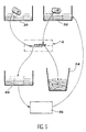
- a box 50 contains new plates, which are mounted in the lower indentation of the gate 2.
- the box 52 contains plates that were used a single time. These plates are mounted in the upper indentation of the gate 2. The gate is then ready for a pouring cycle.
- the gate After pouring, the gate is opened and the plates are withdrawn.
- the lower plate, used once, is recovered in the box 54. It is given a cleaning in 56, and then goes into box 52.
- the upper plate, which was used twice, is discarded into the garbage can 58.
- the invention relates therefore to a process comprising a step of cleaning, reconditioning or repairing a used refractory plate.
- the invention plate can also have more than one hole, e.g., two. This offers the advantage of having a new pouring hole when the plate is reused.
- the surfaces that produce the joint with the internal nozzle and with the collecting nozzle respectively are also new. The cleaning of the plate is facilitated.
- the plate can be reused so that its old support face becomes its sliding face and vice versa. But the same face can also be reused as the support face or as the sliding face provided these are different working zones of the plate.
Landscapes
- Engineering & Computer Science (AREA)
- Mechanical Engineering (AREA)
- Casting Support Devices, Ladles, And Melt Control Thereby (AREA)
- Sliding Valves (AREA)
- Forms Removed On Construction Sites Or Auxiliary Members Thereof (AREA)
- Pens And Brushes (AREA)
- External Artificial Organs (AREA)
- Cartons (AREA)
- Manufacture Of Tobacco Products (AREA)
- Thyristors (AREA)
- Processing And Handling Of Plastics And Other Materials For Molding In General (AREA)
Applications Claiming Priority (3)
| Application Number | Priority Date | Filing Date | Title |
|---|---|---|---|
| FR9512912 | 1995-10-27 | ||
| FR9512912A FR2740368B1 (fr) | 1995-10-27 | 1995-10-27 | Procede de reutilisation de plaques de fermeture a tiroir et plaque pour cette fermeture |
| EP96937231A EP0817692B1 (fr) | 1995-10-27 | 1996-10-25 | Procede permettant la reutilisation de plaques pour porte a coulisse et plaque pour cette fermeture |
Related Parent Applications (1)
| Application Number | Title | Priority Date | Filing Date |
|---|---|---|---|
| EP96937231A Division EP0817692B1 (fr) | 1995-10-27 | 1996-10-25 | Procede permettant la reutilisation de plaques pour porte a coulisse et plaque pour cette fermeture |
Publications (2)
| Publication Number | Publication Date |
|---|---|
| EP1103326A1 true EP1103326A1 (fr) | 2001-05-30 |
| EP1103326B1 EP1103326B1 (fr) | 2005-02-16 |
Family
ID=9484141
Family Applications (2)
| Application Number | Title | Priority Date | Filing Date |
|---|---|---|---|
| EP96937231A Expired - Lifetime EP0817692B1 (fr) | 1995-10-27 | 1996-10-25 | Procede permettant la reutilisation de plaques pour porte a coulisse et plaque pour cette fermeture |
| EP01201065A Revoked EP1103326B1 (fr) | 1995-10-27 | 1996-10-25 | Plaque réfractaire pour fermeture à tiroir et la fermeture à tiroir |
Family Applications Before (1)
| Application Number | Title | Priority Date | Filing Date |
|---|---|---|---|
| EP96937231A Expired - Lifetime EP0817692B1 (fr) | 1995-10-27 | 1996-10-25 | Procede permettant la reutilisation de plaques pour porte a coulisse et plaque pour cette fermeture |
Country Status (24)
| Country | Link |
|---|---|
| US (1) | US5893492A (fr) |
| EP (2) | EP0817692B1 (fr) |
| JP (1) | JP4391588B2 (fr) |
| KR (1) | KR100438267B1 (fr) |
| CN (1) | CN1072078C (fr) |
| AT (2) | ATE289240T1 (fr) |
| AU (1) | AU715693B2 (fr) |
| BR (1) | BR9606719A (fr) |
| CA (1) | CA2208093C (fr) |
| CZ (1) | CZ292857B6 (fr) |
| DE (2) | DE69634368T2 (fr) |
| ES (2) | ES2234762T3 (fr) |
| FR (1) | FR2740368B1 (fr) |
| HU (1) | HU219867B (fr) |
| PL (1) | PL181836B1 (fr) |
| PT (2) | PT1103326E (fr) |
| RU (1) | RU2165335C2 (fr) |
| SI (1) | SI0817692T1 (fr) |
| SK (1) | SK283336B6 (fr) |
| TR (1) | TR199700551T1 (fr) |
| TW (1) | TW328967B (fr) |
| UA (1) | UA52593C2 (fr) |
| WO (1) | WO1997015410A1 (fr) |
| ZA (1) | ZA968719B (fr) |
Cited By (1)
| Publication number | Priority date | Publication date | Assignee | Title |
|---|---|---|---|---|
| WO2003041894A3 (fr) * | 2001-11-13 | 2004-05-13 | Vesuvius Crucible Co | Plaque de regulation a trous et a bords multiples pour porte coulissante lineaire |
Families Citing this family (7)
| Publication number | Priority date | Publication date | Assignee | Title |
|---|---|---|---|---|
| RU2352436C2 (ru) | 2003-07-22 | 2009-04-20 | Везувиус Груп С.А. | Способ определения возможности повторного использования или признания негодной огнеупорной плиты шиберного затвора и устройство для его осуществления |
| RU2333073C2 (ru) * | 2006-09-06 | 2008-09-10 | Владимир Иванович Золотухин | Огнеупорная плита шиберного затвора (варианты) и шиберный затвор литейного ковша (варианты) |
| ES2442316T3 (es) * | 2008-04-17 | 2014-02-11 | Stopinc Aktiengesellschaft | Cierre corredizo para un recipiente que contiene un caldo metálico |
| EP2386368A1 (fr) * | 2010-03-19 | 2011-11-16 | Vesuvius Group S.A | Busette interne pour le transfert de métal liquide contenu dans un récipient, système de clamage de cette busette et dispositif de coulée |
| DE102012209504A1 (de) * | 2012-06-05 | 2013-12-05 | Sms Siemag Ag | Verfahren zum Öffnen und Schließen einer Abstichöffnung eines metallurgischen Schmelzgefäßes und metallurgisches Schmelzgefäß |
| CN104942275B (zh) * | 2015-07-09 | 2017-12-22 | 华北理工大学 | 连铸用滑动水口及其减少浸入式水口偏流的方法 |
| TWI717455B (zh) | 2016-01-25 | 2021-02-01 | 比利時商維蘇威集團股份有限公司 | 滑動閘閥板、金屬殼及滑動閘閥 |
Citations (8)
| Publication number | Priority date | Publication date | Assignee | Title |
|---|---|---|---|---|
| FR2350161A1 (fr) * | 1976-05-08 | 1977-12-02 | Stopinc Ag | Plaque tiroir composite pour fermeture a tiroir |
| GB2151754A (en) * | 1983-12-16 | 1985-07-24 | Didier Werke Ag | Refractory valve plates for sliding gate valves |
| JPS6138774A (ja) * | 1985-06-13 | 1986-02-24 | Kurosaki Refract Co Ltd | スライデイングノズル装置におけるプレ−ト使用法 |
| EP0194990A2 (fr) * | 1985-03-15 | 1986-09-17 | Vesuvius International Corporation | Dispositif de serrage d'un élément d'usure d'une fermeture coulissante de conteneur métallurgique |
| FR2625928A1 (fr) * | 1988-01-15 | 1989-07-21 | Stopinc Ag | Plaque obturatrice pour fermeture a coulisse d'un recipient metallurgique, et fermeture a coulisse comportant de telles plaques |
| EP0498915A1 (fr) * | 1990-01-30 | 1992-08-19 | Cerafer S.A.R.L. | Plaque coulissante pour obturateurs coulissants de récipients métallurgiques |
| US5174908A (en) * | 1989-03-03 | 1992-12-29 | Flo-Con Systems, Inc. | Non-reversible sliding gate, valve and method |
| EP0587485A1 (fr) * | 1992-09-09 | 1994-03-16 | Sollac | Tiroir linéaire de poche à acier |
Family Cites Families (5)
| Publication number | Priority date | Publication date | Assignee | Title |
|---|---|---|---|---|
| DE3412388C2 (de) * | 1984-04-03 | 1986-10-02 | Didier-Werke Ag, 6200 Wiesbaden | Feuerfester Eintauchausguß |
| CH660313A5 (de) * | 1984-04-24 | 1987-04-15 | Stopinc Ag | Verfahren zur herstellung einer verschlussplatteneinheit fuer einen schiebeverschluss. |
| SU1488126A1 (ru) * | 1987-07-08 | 1989-06-23 | И.А. Кривцов и М.И. Кривцов | Устройство дл выпуска жидкого металла из ковша |
| US5188743A (en) * | 1989-03-03 | 1993-02-23 | Flo-Con Systems, Inc. | Plate, changer, plate and method |
| US5211857A (en) * | 1990-10-31 | 1993-05-18 | Leco Corporation | Gate safety arrangement |
-
1995
- 1995-10-27 FR FR9512912A patent/FR2740368B1/fr not_active Expired - Lifetime
-
1996
- 1996-10-16 ZA ZA968719A patent/ZA968719B/xx unknown
- 1996-10-24 TW TW085113071A patent/TW328967B/zh not_active IP Right Cessation
- 1996-10-25 PT PT01201065T patent/PT1103326E/pt unknown
- 1996-10-25 ES ES01201065T patent/ES2234762T3/es not_active Expired - Lifetime
- 1996-10-25 WO PCT/EP1996/004640 patent/WO1997015410A1/fr not_active Ceased
- 1996-10-25 JP JP51629197A patent/JP4391588B2/ja not_active Expired - Fee Related
- 1996-10-25 SI SI9630471T patent/SI0817692T1/xx unknown
- 1996-10-25 PL PL96320999A patent/PL181836B1/pl unknown
- 1996-10-25 DE DE69634368T patent/DE69634368T2/de not_active Revoked
- 1996-10-25 AT AT01201065T patent/ATE289240T1/de not_active IP Right Cessation
- 1996-10-25 ES ES96937231T patent/ES2172684T3/es not_active Expired - Lifetime
- 1996-10-25 HU HU9702460A patent/HU219867B/hu not_active IP Right Cessation
- 1996-10-25 KR KR1019970704389A patent/KR100438267B1/ko not_active Expired - Fee Related
- 1996-10-25 SK SK852-97A patent/SK283336B6/sk not_active IP Right Cessation
- 1996-10-25 EP EP96937231A patent/EP0817692B1/fr not_active Expired - Lifetime
- 1996-10-25 BR BR9606719A patent/BR9606719A/pt not_active IP Right Cessation
- 1996-10-25 AT AT96937231T patent/ATE213981T1/de active
- 1996-10-25 PT PT96937231T patent/PT817692E/pt unknown
- 1996-10-25 US US08/860,555 patent/US5893492A/en not_active Expired - Lifetime
- 1996-10-25 EP EP01201065A patent/EP1103326B1/fr not_active Revoked
- 1996-10-25 TR TR97/00551T patent/TR199700551T1/xx unknown
- 1996-10-25 CA CA002208093A patent/CA2208093C/fr not_active Expired - Lifetime
- 1996-10-25 CZ CZ19971995A patent/CZ292857B6/cs not_active IP Right Cessation
- 1996-10-25 DE DE69619655T patent/DE69619655T2/de not_active Expired - Lifetime
- 1996-10-25 UA UA97063424A patent/UA52593C2/uk unknown
- 1996-10-25 CN CN96191301A patent/CN1072078C/zh not_active Expired - Lifetime
- 1996-10-25 RU RU97112863/02A patent/RU2165335C2/ru not_active IP Right Cessation
- 1996-10-25 AU AU74920/96A patent/AU715693B2/en not_active Ceased
Patent Citations (8)
| Publication number | Priority date | Publication date | Assignee | Title |
|---|---|---|---|---|
| FR2350161A1 (fr) * | 1976-05-08 | 1977-12-02 | Stopinc Ag | Plaque tiroir composite pour fermeture a tiroir |
| GB2151754A (en) * | 1983-12-16 | 1985-07-24 | Didier Werke Ag | Refractory valve plates for sliding gate valves |
| EP0194990A2 (fr) * | 1985-03-15 | 1986-09-17 | Vesuvius International Corporation | Dispositif de serrage d'un élément d'usure d'une fermeture coulissante de conteneur métallurgique |
| JPS6138774A (ja) * | 1985-06-13 | 1986-02-24 | Kurosaki Refract Co Ltd | スライデイングノズル装置におけるプレ−ト使用法 |
| FR2625928A1 (fr) * | 1988-01-15 | 1989-07-21 | Stopinc Ag | Plaque obturatrice pour fermeture a coulisse d'un recipient metallurgique, et fermeture a coulisse comportant de telles plaques |
| US5174908A (en) * | 1989-03-03 | 1992-12-29 | Flo-Con Systems, Inc. | Non-reversible sliding gate, valve and method |
| EP0498915A1 (fr) * | 1990-01-30 | 1992-08-19 | Cerafer S.A.R.L. | Plaque coulissante pour obturateurs coulissants de récipients métallurgiques |
| EP0587485A1 (fr) * | 1992-09-09 | 1994-03-16 | Sollac | Tiroir linéaire de poche à acier |
Non-Patent Citations (1)
| Title |
|---|
| PATENT ABSTRACTS OF JAPAN vol. 010, no. 196 (M - 497) 10 July 1986 (1986-07-10) * |
Cited By (2)
| Publication number | Priority date | Publication date | Assignee | Title |
|---|---|---|---|---|
| WO2003041894A3 (fr) * | 2001-11-13 | 2004-05-13 | Vesuvius Crucible Co | Plaque de regulation a trous et a bords multiples pour porte coulissante lineaire |
| AU2002350171B2 (en) * | 2001-11-13 | 2007-02-15 | Vesuvius Crucible Company | Multi-hole, multi-edge control plate for linear sliding gate |
Also Published As
Similar Documents
| Publication | Publication Date | Title |
|---|---|---|
| US4245761A (en) | Continuous casting | |
| US4327847A (en) | Sliding gate nozzles | |
| US3396961A (en) | Precast taphole assembly | |
| EP1103326B1 (fr) | Plaque réfractaire pour fermeture à tiroir et la fermeture à tiroir | |
| US4279844A (en) | Method for the repair of runner for molten metal | |
| CA1043073A (fr) | Coulee de metaux fondus | |
| US4314659A (en) | Rotary valve | |
| EP0636441A1 (fr) | Busette de coulée pour un panier de coulée | |
| USRE36364E (en) | Slide gate valve having a cementless joint between the valve and the metallurgical vessel | |
| CA1126472A (fr) | Vanne tournante | |
| US4165026A (en) | Tundish with expendable lining and easily removable nozzle | |
| GB2198979A (en) | Rotary sliding gate valves for metallurgical vessels | |
| EP3825034B1 (fr) | Plaque coulissante recyclée d'un appareil de décharge de métal en fusion et procédés de recyclage associés | |
| JP4535594B2 (ja) | 連続鋳造機の浸漬ノズル交換装置 | |
| EP0080248B1 (fr) | Composants réfractaires | |
| JP3727467B2 (ja) | 溶融金属容器の残鋼残滓排出装置 | |
| MXPA97004699A (en) | Process for reuse of sliding gate plates and plate for this cie | |
| US4004792A (en) | Metallurgical furnace having fluid injection means for a melt in the furnace | |
| KR100284533B1 (ko) | 수평연속주조설비의 몰드 교체장치 | |
| KR100851214B1 (ko) | 휠러 겸용 래들 개공구 | |
| RU7915U1 (ru) | Устройство для разливки жидкого металла | |
| EP0043670A1 (fr) | Coulée des métaux et récipients revêtus pour la coulée | |
| JPH05162762A (ja) | 液体金属用容器のタップホールの閉鎖装置 | |
| JPH074657B2 (ja) | 溶融金属流量制御装置及び溶融金属排出停止法 | |
| Borisov et al. | Casting Steel From Ladles With Slide Gate Nozzles |
Legal Events
| Date | Code | Title | Description |
|---|---|---|---|
| PUAI | Public reference made under article 153(3) epc to a published international application that has entered the european phase |
Free format text: ORIGINAL CODE: 0009012 |
|
| AC | Divisional application: reference to earlier application |
Ref document number: 817692 Country of ref document: EP |
|
| AK | Designated contracting states |
Kind code of ref document: A1 Designated state(s): AT BE DE ES FI GB IT PT SE |
|
| AX | Request for extension of the european patent |
Free format text: SI |
|
| 17P | Request for examination filed |
Effective date: 20011130 |
|
| AKX | Designation fees paid |
Free format text: AT BE DE ES FI GB IT PT SE |
|
| 17Q | First examination report despatched |
Effective date: 20030228 |
|
| GRAP | Despatch of communication of intention to grant a patent |
Free format text: ORIGINAL CODE: EPIDOSNIGR1 |
|
| RTI1 | Title (correction) |
Free format text: REFRACTORY PLATE FOR SLIDE GATE AND THE SLIDE GATE |
|
| GRAS | Grant fee paid |
Free format text: ORIGINAL CODE: EPIDOSNIGR3 |
|
| GRAA | (expected) grant |
Free format text: ORIGINAL CODE: 0009210 |
|
| AC | Divisional application: reference to earlier application |
Ref document number: 0817692 Country of ref document: EP Kind code of ref document: P |
|
| AK | Designated contracting states |
Kind code of ref document: B1 Designated state(s): AT BE DE ES FI GB IT PT SE |
|
| REG | Reference to a national code |
Ref country code: GB Ref legal event code: FG4D |
|
| REF | Corresponds to: |
Ref document number: 69634368 Country of ref document: DE Date of ref document: 20050324 Kind code of ref document: P |
|
| REG | Reference to a national code |
Ref country code: SE Ref legal event code: TRGR |
|
| REG | Reference to a national code |
Ref country code: PT Ref legal event code: SC4A Free format text: AVAILABILITY OF NATIONAL TRANSLATION Effective date: 20050429 |
|
| REG | Reference to a national code |
Ref country code: ES Ref legal event code: FG2A Ref document number: 2234762 Country of ref document: ES Kind code of ref document: T3 |
|
| PGFP | Annual fee paid to national office [announced via postgrant information from national office to epo] |
Ref country code: AT Payment date: 20051004 Year of fee payment: 10 |
|
| PGFP | Annual fee paid to national office [announced via postgrant information from national office to epo] |
Ref country code: PT Payment date: 20051007 Year of fee payment: 10 |
|
| PGFP | Annual fee paid to national office [announced via postgrant information from national office to epo] |
Ref country code: GB Payment date: 20051019 Year of fee payment: 10 |
|
| PGFP | Annual fee paid to national office [announced via postgrant information from national office to epo] |
Ref country code: ES Payment date: 20051026 Year of fee payment: 10 |
|
| PGFP | Annual fee paid to national office [announced via postgrant information from national office to epo] |
Ref country code: SE Payment date: 20051027 Year of fee payment: 10 |
|
| PGFP | Annual fee paid to national office [announced via postgrant information from national office to epo] |
Ref country code: FI Payment date: 20051028 Year of fee payment: 10 |
|
| PLBI | Opposition filed |
Free format text: ORIGINAL CODE: 0009260 |
|
| PGFP | Annual fee paid to national office [announced via postgrant information from national office to epo] |
Ref country code: BE Payment date: 20051122 Year of fee payment: 10 |
|
| PGFP | Annual fee paid to national office [announced via postgrant information from national office to epo] |
Ref country code: DE Payment date: 20051130 Year of fee payment: 10 |
|
| PLAX | Notice of opposition and request to file observation + time limit sent |
Free format text: ORIGINAL CODE: EPIDOSNOBS2 |
|
| 26 | Opposition filed |
Opponent name: STOPINC AG Effective date: 20051109 |
|
| RDAF | Communication despatched that patent is revoked |
Free format text: ORIGINAL CODE: EPIDOSNREV1 |
|
| PLBB | Reply of patent proprietor to notice(s) of opposition received |
Free format text: ORIGINAL CODE: EPIDOSNOBS3 |
|
| RDAG | Patent revoked |
Free format text: ORIGINAL CODE: 0009271 |
|
| STAA | Information on the status of an ep patent application or granted ep patent |
Free format text: STATUS: PATENT REVOKED |
|
| 27W | Patent revoked |
Effective date: 20060512 |
|
| GBPR | Gb: patent revoked under art. 102 of the ep convention designating the uk as contracting state |
Free format text: 20060512 |
|
| PGFP | Annual fee paid to national office [announced via postgrant information from national office to epo] |
Ref country code: IT Payment date: 20061031 Year of fee payment: 11 |
|
| REG | Reference to a national code |
Ref country code: PT Ref legal event code: MP4A Effective date: 20060828 |
|
| REG | Reference to a national code |
Ref country code: SE Ref legal event code: ECNC |