EP1103404A1 - Dispositif de lubrification pour vehicule hybride - Google Patents
Dispositif de lubrification pour vehicule hybride Download PDFInfo
- Publication number
- EP1103404A1 EP1103404A1 EP00125518A EP00125518A EP1103404A1 EP 1103404 A1 EP1103404 A1 EP 1103404A1 EP 00125518 A EP00125518 A EP 00125518A EP 00125518 A EP00125518 A EP 00125518A EP 1103404 A1 EP1103404 A1 EP 1103404A1
- Authority
- EP
- European Patent Office
- Prior art keywords
- oil pressure
- hybrid vehicle
- engine
- supply source
- oil
- Prior art date
- Legal status (The legal status is an assumption and is not a legal conclusion. Google has not performed a legal analysis and makes no representation as to the accuracy of the status listed.)
- Granted
Links
Images


Classifications
-
- B—PERFORMING OPERATIONS; TRANSPORTING
- B60—VEHICLES IN GENERAL
- B60K—ARRANGEMENT OR MOUNTING OF PROPULSION UNITS OR OF TRANSMISSIONS IN VEHICLES; ARRANGEMENT OR MOUNTING OF PLURAL DIVERSE PRIME-MOVERS IN VEHICLES; AUXILIARY DRIVES FOR VEHICLES; INSTRUMENTATION OR DASHBOARDS FOR VEHICLES; ARRANGEMENTS IN CONNECTION WITH COOLING, AIR INTAKE, GAS EXHAUST OR FUEL SUPPLY OF PROPULSION UNITS IN VEHICLES
- B60K6/00—Arrangement or mounting of plural diverse prime-movers for mutual or common propulsion, e.g. hybrid propulsion systems comprising electric motors and internal combustion engines
- B60K6/20—Arrangement or mounting of plural diverse prime-movers for mutual or common propulsion, e.g. hybrid propulsion systems comprising electric motors and internal combustion engines the prime-movers consisting of electric motors and internal combustion engines, e.g. HEVs
- B60K6/42—Arrangement or mounting of plural diverse prime-movers for mutual or common propulsion, e.g. hybrid propulsion systems comprising electric motors and internal combustion engines the prime-movers consisting of electric motors and internal combustion engines, e.g. HEVs characterised by the architecture of the hybrid electric vehicle
- B60K6/48—Parallel type
-
- B—PERFORMING OPERATIONS; TRANSPORTING
- B60—VEHICLES IN GENERAL
- B60K—ARRANGEMENT OR MOUNTING OF PROPULSION UNITS OR OF TRANSMISSIONS IN VEHICLES; ARRANGEMENT OR MOUNTING OF PLURAL DIVERSE PRIME-MOVERS IN VEHICLES; AUXILIARY DRIVES FOR VEHICLES; INSTRUMENTATION OR DASHBOARDS FOR VEHICLES; ARRANGEMENTS IN CONNECTION WITH COOLING, AIR INTAKE, GAS EXHAUST OR FUEL SUPPLY OF PROPULSION UNITS IN VEHICLES
- B60K6/00—Arrangement or mounting of plural diverse prime-movers for mutual or common propulsion, e.g. hybrid propulsion systems comprising electric motors and internal combustion engines
- B60K6/20—Arrangement or mounting of plural diverse prime-movers for mutual or common propulsion, e.g. hybrid propulsion systems comprising electric motors and internal combustion engines the prime-movers consisting of electric motors and internal combustion engines, e.g. HEVs
- B60K6/50—Architecture of the driveline characterised by arrangement or kind of transmission units
- B60K6/54—Transmission for changing ratio
- B60K6/543—Transmission for changing ratio the transmission being a continuously variable transmission
-
- F—MECHANICAL ENGINEERING; LIGHTING; HEATING; WEAPONS; BLASTING
- F01—MACHINES OR ENGINES IN GENERAL; ENGINE PLANTS IN GENERAL; STEAM ENGINES
- F01M—LUBRICATING OF MACHINES OR ENGINES IN GENERAL; LUBRICATING INTERNAL COMBUSTION ENGINES; CRANKCASE VENTILATING
- F01M1/00—Pressure lubrication
- F01M1/12—Closed-circuit lubricating systems not provided for in groups F01M1/02 - F01M1/10
-
- F—MECHANICAL ENGINEERING; LIGHTING; HEATING; WEAPONS; BLASTING
- F16—ENGINEERING ELEMENTS AND UNITS; GENERAL MEASURES FOR PRODUCING AND MAINTAINING EFFECTIVE FUNCTIONING OF MACHINES OR INSTALLATIONS; THERMAL INSULATION IN GENERAL
- F16H—GEARING
- F16H57/00—General details of gearing
- F16H57/04—Features relating to lubrication or cooling or heating
- F16H57/0434—Features relating to lubrication or cooling or heating relating to lubrication supply, e.g. pumps; Pressure control
-
- F—MECHANICAL ENGINEERING; LIGHTING; HEATING; WEAPONS; BLASTING
- F16—ENGINEERING ELEMENTS AND UNITS; GENERAL MEASURES FOR PRODUCING AND MAINTAINING EFFECTIVE FUNCTIONING OF MACHINES OR INSTALLATIONS; THERMAL INSULATION IN GENERAL
- F16H—GEARING
- F16H61/00—Control functions within control units of change-speed- or reversing-gearings for conveying rotary motion ; Control of exclusively fluid gearing, friction gearing, gearings with endless flexible members or other particular types of gearing
- F16H61/0021—Generation or control of line pressure
- F16H61/0025—Supply of control fluid; Pumps therefor
-
- F—MECHANICAL ENGINEERING; LIGHTING; HEATING; WEAPONS; BLASTING
- F16—ENGINEERING ELEMENTS AND UNITS; GENERAL MEASURES FOR PRODUCING AND MAINTAINING EFFECTIVE FUNCTIONING OF MACHINES OR INSTALLATIONS; THERMAL INSULATION IN GENERAL
- F16H—GEARING
- F16H61/00—Control functions within control units of change-speed- or reversing-gearings for conveying rotary motion ; Control of exclusively fluid gearing, friction gearing, gearings with endless flexible members or other particular types of gearing
- F16H61/0021—Generation or control of line pressure
- F16H61/0025—Supply of control fluid; Pumps therefor
- F16H61/0031—Supply of control fluid; Pumps therefor using auxiliary pumps, e.g. pump driven by a different power source than the engine
-
- F—MECHANICAL ENGINEERING; LIGHTING; HEATING; WEAPONS; BLASTING
- F16—ENGINEERING ELEMENTS AND UNITS; GENERAL MEASURES FOR PRODUCING AND MAINTAINING EFFECTIVE FUNCTIONING OF MACHINES OR INSTALLATIONS; THERMAL INSULATION IN GENERAL
- F16H—GEARING
- F16H61/00—Control functions within control units of change-speed- or reversing-gearings for conveying rotary motion ; Control of exclusively fluid gearing, friction gearing, gearings with endless flexible members or other particular types of gearing
- F16H61/66—Control functions within control units of change-speed- or reversing-gearings for conveying rotary motion ; Control of exclusively fluid gearing, friction gearing, gearings with endless flexible members or other particular types of gearing specially adapted for continuously variable gearings
- F16H61/662—Control functions within control units of change-speed- or reversing-gearings for conveying rotary motion ; Control of exclusively fluid gearing, friction gearing, gearings with endless flexible members or other particular types of gearing specially adapted for continuously variable gearings with endless flexible members
- F16H61/66272—Control functions within control units of change-speed- or reversing-gearings for conveying rotary motion ; Control of exclusively fluid gearing, friction gearing, gearings with endless flexible members or other particular types of gearing specially adapted for continuously variable gearings with endless flexible members characterised by means for controlling the torque transmitting capability of the gearing
-
- B—PERFORMING OPERATIONS; TRANSPORTING
- B60—VEHICLES IN GENERAL
- B60L—PROPULSION OF ELECTRICALLY-PROPELLED VEHICLES; SUPPLYING ELECTRIC POWER FOR AUXILIARY EQUIPMENT OF ELECTRICALLY-PROPELLED VEHICLES; ELECTRODYNAMIC BRAKE SYSTEMS FOR VEHICLES IN GENERAL; MAGNETIC SUSPENSION OR LEVITATION FOR VEHICLES; MONITORING OPERATING VARIABLES OF ELECTRICALLY-PROPELLED VEHICLES; ELECTRIC SAFETY DEVICES FOR ELECTRICALLY-PROPELLED VEHICLES
- B60L2260/00—Operating Modes
- B60L2260/10—Temporary overload
- B60L2260/14—Temporary overload of transmissions
-
- F—MECHANICAL ENGINEERING; LIGHTING; HEATING; WEAPONS; BLASTING
- F01—MACHINES OR ENGINES IN GENERAL; ENGINE PLANTS IN GENERAL; STEAM ENGINES
- F01M—LUBRICATING OF MACHINES OR ENGINES IN GENERAL; LUBRICATING INTERNAL COMBUSTION ENGINES; CRANKCASE VENTILATING
- F01M1/00—Pressure lubrication
- F01M1/12—Closed-circuit lubricating systems not provided for in groups F01M1/02 - F01M1/10
- F01M2001/123—Closed-circuit lubricating systems not provided for in groups F01M1/02 - F01M1/10 using two or more pumps
-
- F—MECHANICAL ENGINEERING; LIGHTING; HEATING; WEAPONS; BLASTING
- F16—ENGINEERING ELEMENTS AND UNITS; GENERAL MEASURES FOR PRODUCING AND MAINTAINING EFFECTIVE FUNCTIONING OF MACHINES OR INSTALLATIONS; THERMAL INSULATION IN GENERAL
- F16H—GEARING
- F16H61/00—Control functions within control units of change-speed- or reversing-gearings for conveying rotary motion ; Control of exclusively fluid gearing, friction gearing, gearings with endless flexible members or other particular types of gearing
- F16H61/66—Control functions within control units of change-speed- or reversing-gearings for conveying rotary motion ; Control of exclusively fluid gearing, friction gearing, gearings with endless flexible members or other particular types of gearing specially adapted for continuously variable gearings
-
- Y—GENERAL TAGGING OF NEW TECHNOLOGICAL DEVELOPMENTS; GENERAL TAGGING OF CROSS-SECTIONAL TECHNOLOGIES SPANNING OVER SEVERAL SECTIONS OF THE IPC; TECHNICAL SUBJECTS COVERED BY FORMER USPC CROSS-REFERENCE ART COLLECTIONS [XRACs] AND DIGESTS
- Y02—TECHNOLOGIES OR APPLICATIONS FOR MITIGATION OR ADAPTATION AGAINST CLIMATE CHANGE
- Y02T—CLIMATE CHANGE MITIGATION TECHNOLOGIES RELATED TO TRANSPORTATION
- Y02T10/00—Road transport of goods or passengers
- Y02T10/60—Other road transportation technologies with climate change mitigation effect
- Y02T10/62—Hybrid vehicles
-
- Y—GENERAL TAGGING OF NEW TECHNOLOGICAL DEVELOPMENTS; GENERAL TAGGING OF CROSS-SECTIONAL TECHNOLOGIES SPANNING OVER SEVERAL SECTIONS OF THE IPC; TECHNICAL SUBJECTS COVERED BY FORMER USPC CROSS-REFERENCE ART COLLECTIONS [XRACs] AND DIGESTS
- Y10—TECHNICAL SUBJECTS COVERED BY FORMER USPC
- Y10S—TECHNICAL SUBJECTS COVERED BY FORMER USPC CROSS-REFERENCE ART COLLECTIONS [XRACs] AND DIGESTS
- Y10S903/00—Hybrid electric vehicles, HEVS
- Y10S903/902—Prime movers comprising electrical and internal combustion motors
- Y10S903/903—Prime movers comprising electrical and internal combustion motors having energy storing means, e.g. battery, capacitor
-
- Y—GENERAL TAGGING OF NEW TECHNOLOGICAL DEVELOPMENTS; GENERAL TAGGING OF CROSS-SECTIONAL TECHNOLOGIES SPANNING OVER SEVERAL SECTIONS OF THE IPC; TECHNICAL SUBJECTS COVERED BY FORMER USPC CROSS-REFERENCE ART COLLECTIONS [XRACs] AND DIGESTS
- Y10—TECHNICAL SUBJECTS COVERED BY FORMER USPC
- Y10S—TECHNICAL SUBJECTS COVERED BY FORMER USPC CROSS-REFERENCE ART COLLECTIONS [XRACs] AND DIGESTS
- Y10S903/00—Hybrid electric vehicles, HEVS
- Y10S903/902—Prime movers comprising electrical and internal combustion motors
- Y10S903/903—Prime movers comprising electrical and internal combustion motors having energy storing means, e.g. battery, capacitor
- Y10S903/904—Component specially adapted for hev
- Y10S903/909—Gearing
-
- Y—GENERAL TAGGING OF NEW TECHNOLOGICAL DEVELOPMENTS; GENERAL TAGGING OF CROSS-SECTIONAL TECHNOLOGIES SPANNING OVER SEVERAL SECTIONS OF THE IPC; TECHNICAL SUBJECTS COVERED BY FORMER USPC CROSS-REFERENCE ART COLLECTIONS [XRACs] AND DIGESTS
- Y10—TECHNICAL SUBJECTS COVERED BY FORMER USPC
- Y10S—TECHNICAL SUBJECTS COVERED BY FORMER USPC CROSS-REFERENCE ART COLLECTIONS [XRACs] AND DIGESTS
- Y10S903/00—Hybrid electric vehicles, HEVS
- Y10S903/902—Prime movers comprising electrical and internal combustion motors
- Y10S903/903—Prime movers comprising electrical and internal combustion motors having energy storing means, e.g. battery, capacitor
- Y10S903/904—Component specially adapted for hev
- Y10S903/915—Specific drive or transmission adapted for hev
- Y10S903/917—Specific drive or transmission adapted for hev with transmission for changing gear ratio
- Y10S903/918—Continuously variable
Definitions
- the present invention relates to a lubricating oil for a hybrid vehicle and in particular to a lubricating structure for a hybrid vehicle that can run by an engine or a motor.
- a hybrid vehicle which is adapted to run by a driving motor disposed on an axle side of a transmission (JP-A-10-324177).
- a secondary oil pressure driving source in addition to a primary oil pressure supply source for driving the transmission when the engine is driven, and this secondary oil pressure driving source is selectively used in place of the primary oil pressure supply source when the engine is re-started from a state in which the engine is stopped.
- reference numeral 51 denotes a manual valve, which is a type of manual valve which is connected to a forward clutch 52 and a reverse clutch 53. Additionally, the manual valve 51 is connected via a check valve 54 to a primary oil pressure supply source X (not shown) which is driven by an engine, and a secondary oil pressure supply source Y is connected to a downstream side of the check valve 54 for supplying a hydraulic fluid to the manual valve 51 instead of the primary oil pressure supply source when the engine is stopped.
- a manual valve which is a type of manual valve which is connected to a forward clutch 52 and a reverse clutch 53. Additionally, the manual valve 51 is connected via a check valve 54 to a primary oil pressure supply source X (not shown) which is driven by an engine, and a secondary oil pressure supply source Y is connected to a downstream side of the check valve 54 for supplying a hydraulic fluid to the manual valve 51 instead of the primary oil pressure supply source when the engine is stopped.
- the secondary oil pressure supply source Y is intended to supply a hydraulic fluid to the manual valve 51 from a pump 56 which operates on a motor 55, and connected to a downstream side of the pump 56 along an oil pressure path are a relief valve 57 and a check valve 58.
- This relief valve 57 functions to set constant the pressure of a hydraulic fluid supplied from the pump 56, and a drain for the relief valve 57 is adapted to return to an oil pan 59.
- an object of the invention is to provide a lubricating structure for a hybrid vehicle which can eliminate a shortage of lubricating oil while the secondary oil pressure supply source Y is in use.
- a hybrid vehicle comprising a transmission (for example, a CVT 6 in an embodiment of the invention) provided along a power train path between an engine (for example, an engine E in the embodiment) and a drive wheel (for example, a drive wheel W in the embodiment) which operates on oil pressure from an oil pressure supply source (for example, oil pumps 4, 25 in the embodiment) and a clutch (for example, a start clutch 15 in the embodiment) provided on a drive wheel side of the transmission, wherein the drive wheel can be driven by an electric motor (for example, a secondary motor generator M2 in the embodiment) in the event that the power train path is interrupted by the clutch, there is provided a lubricating structure for a hybrid vehicle characterized in that the oil pressure supply source is constituted by a primary oil pressure supply source (for example, mainly the oil pump 4 in the embodiment) adapted to be driven by the engine and a secondary oil pressure supply source (for example, mainly the oil pump 25 in the embodiment)
- an excess oil from the drain circuit of the secondary oil pressure supply source is supplied to lubricate the transmission and the electric motor.
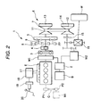
- Fig. 2 is a schematic diagram showing the construction of a hybrid vehicle according to an embodiment of the invention.
- a hybrid vehicle 1 includes a control unit (not shown), and an engine E is started by a primary motor generator M1 connected to the engine E, and power is generated using the engine as a power source therefor so as to keep a battery B charged.
- this primary motor generator Ml also assists in driving the engine E when a sufficient driving force cannot be obtained through a cooperation of a secondary motor generator M2, which will be described later and the engine E.
- the primary motor generator M1 can be used as a starter when starting the engine E.
- a power drive unit 2 is provided between the primary motor generator M1 and a battery B.
- the output shaft of the engine E and the rotating shaft of the primary motor generator Ml which is connected thereto are constructed so as rotate a dual-mass flywheel 3 and to rotatively drive an oil pump 4. Additionally, the output shaft of the engine E and the rotating shaft of the primary motor generator M1 are connected to a drive pulley 7 of a CVT 6 via a forward and backward movement switching planetary gear 5.
- the forward and backward movement switching planetary gear 5 is constructed so as to selectively engage with hydraulically operated friction elements 8, 9 through a pressure governing valve (a pressure governing valve 22 shown in Fig. 1 which will be described later) connected to a selector lever by manipulating the selector lever as required.
- a pressure governing valve a pressure governing valve 22 shown in Fig. 1 which will be described later
- the rotation of the drive pulley 7 is transmitted to a driven pulley 12 via a metallic belt 11.
- the rotation ratio of the drive pulley 7 and driven pulley I2 is determined by diameters of portions of the respective pulleys around which the metallic belt 11 is wound, and the belt wound-around diameters are controlled by pressing forces applied by oil pressures imparted to side chambers 13, 14 of the respective pulleys.
- oil pressures are generated by the oil pump 4 to be supplied to the respective side chambers 13, 14. Additionally, the rotation of the driven pulley 12 is transmitted to the drive wheel W via a starting clutch 15 and a differential 16.
- An intake manifold 17 of the engine E is connected via a vacuum tank 18 to a brake booster 19 connected to a brake pedal 20.
- a secondary motor generator M2 which is connected to the drive wheel W via the differential 16. Consequently, this hybrid vehicle is constructed so as to perform a motor running through the secondary motor generator M2 in a state in which the power transmission from the engine is interrupted by the starting clutch 15.
- the deceleration regeneration and the driving assistance to the engine E are provided by the secondary motor generator M2.
- Fig. 1 is a hydraulic circuit diagram showing a main part of the invention.
- reference numeral 21 denotes'an oil pan
- the oil pump 4 driven by the engine E is provided along a hydraulic circuit 23 extending from the oil pan 21 to the pressure governing valve 22.
- a control piping 22A for controlling the operation of the pressure governing vale 22 is connected to the pressure governing valve 22, and an operating piping 22B for applying an operation pressure from the oil pump 4 thereto is also connected to the pressure governing valve 22.
- a lubricating piping 22C for lubricating the CVT 6 and the secondary motor generator M2 is also connected to the pressure governing valve 22.
- the pressure governing valve 22 is designed to govern the pressure of the operating piping 22B from the hydraulic circuit 23 with a pressure in proportion to an oil pressure applied to the controlling pipe 22A.
- a hydraulic fluid which becomes extra at the time of governing the pressure is relieved to be discharged into the lubricating piping 22C for use for lubrication (LUB).
- a hydraulic circuit 24 is provided in parallel with the hydraulic circuit 23.
- An oil pump 25 is provided along the hydraulic circuit 24, which has a similar function as that provided along the hydraulic circuit 23.
- the oil pump 25 is driven by a motor 26 and is intended to supply a hydraulic fluid to the CVT 6 instead of the oil pump 4 when the engine is at a halt.
- a one-way valve 27 is interposed along the hydraulic circuit 24, and a relief valve 28 is provided between the one-way valve 27 and the oil pump 25.
- a drain circuit 29 of the relief valve 28 is connected to the lubricating piping 22C, which is connected to the pressure governing valve 22.
- the pressure governing valve 22 is controlled by the hydraulic fluid from the controlling piping 22A, and the hydraulic fluid having a predetermined pressure is supplied from the operating piping 22B to the predetermined side chambers 13, 14 of the CVT 6.
- the hydraulic fluid is distributed to the CVT 6 and the secondary motor generator M2 from the pressure governing valve 22 via the lubricating piping 22C as a lubricating oil.
- the oil pump 25 is then started to operate by the motor 26.
- the supply of the hydraulic fluid to the CVT 6 or the like is secured by the oil pump 25.
- the relief valve 28 is provided along the hydraulic circuit 24 through which the hydraulic fluid is carried by means of the oil pump 25, but since the drain circuit 29 of the relief circuit 28 is not connected to the oil pan 21 but to the lubricating piping 22C, the hydraulic fluid draining from the relief valve 28 is sent to the lubricating piping 22C for use for lubrication.
- the invention is not limited to the above embodiment.
- the invention can be applied to a hybrid vehicle in which a first motor generator M1 is connected via a chain C and pulleys P1, P2 to an end of an engine E opposite to an end where a dual-mass flywheel of a crankshaft is provided.
- a first motor generator M1 is connected via a chain C and pulleys P1, P2 to an end of an engine E opposite to an end where a dual-mass flywheel of a crankshaft is provided.
- a lubricating structure for a hybrid vehicle characterized in that an oil pump 4 adapted to be driven by the engine and an oil pump 25 adapted to be driven by a motor 26 are provided, a relief valve is provided on the oil pump 25 for governing the discharge pressure thereof, and that a drain circuit of the relief valve is connected to the CVT and a lubricating piping 22C of the secondary motor generator.
Landscapes
- Engineering & Computer Science (AREA)
- General Engineering & Computer Science (AREA)
- Mechanical Engineering (AREA)
- Chemical & Material Sciences (AREA)
- Combustion & Propulsion (AREA)
- Transportation (AREA)
- Hybrid Electric Vehicles (AREA)
- Arrangement Of Transmissions (AREA)
- Control Of Vehicle Engines Or Engines For Specific Uses (AREA)
Applications Claiming Priority (2)
| Application Number | Priority Date | Filing Date | Title |
|---|---|---|---|
| JP33503499 | 1999-11-25 | ||
| JP33503499A JP3810601B2 (ja) | 1999-11-25 | 1999-11-25 | ハイブリッド車両の潤滑構造 |
Publications (2)
| Publication Number | Publication Date |
|---|---|
| EP1103404A1 true EP1103404A1 (fr) | 2001-05-30 |
| EP1103404B1 EP1103404B1 (fr) | 2004-01-07 |
Family
ID=18284010
Family Applications (1)
| Application Number | Title | Priority Date | Filing Date |
|---|---|---|---|
| EP00125518A Expired - Lifetime EP1103404B1 (fr) | 1999-11-25 | 2000-11-21 | Dispositif de lubrification pour vehicule hybride |
Country Status (4)
| Country | Link |
|---|---|
| US (1) | US6527074B1 (fr) |
| EP (1) | EP1103404B1 (fr) |
| JP (1) | JP3810601B2 (fr) |
| DE (1) | DE60007602T2 (fr) |
Cited By (7)
| Publication number | Priority date | Publication date | Assignee | Title |
|---|---|---|---|---|
| FR2871209A1 (fr) * | 2004-06-03 | 2005-12-09 | Peugeot Citroen Automobiles Sa | Element de transmission a embrayages humides pour chaine de traction hybride de vehicule automobile, procede de lubrification et/ou de refroidissement, et de commande associe, et vehicule automobile equipe d'un tel element |
| WO2010023097A1 (fr) * | 2008-08-28 | 2010-03-04 | Robert Bosch Gmbh | Système de propulsion hybride |
| WO2010010040A3 (fr) * | 2008-07-24 | 2010-03-18 | Zf Friedrichshafen Ag | Système hydraulique d'un dispositif de boîte de vitesses comprenant une pompe principale de boîte de vitesses et une pompe auxiliaire |
| CN102390251A (zh) * | 2011-08-18 | 2012-03-28 | 上海中科深江电动车辆有限公司 | 混合动力车双动力源离合系统 |
| EP2493716A1 (fr) * | 2009-10-26 | 2012-09-05 | ZF Friedrichshafen AG | Chaîne cinématique de véhicule |
| CN102224032B (zh) * | 2008-12-09 | 2014-03-12 | 博格华纳公司 | 用于混合动力车辆的自动变速器 |
| CN104039574A (zh) * | 2012-02-29 | 2014-09-10 | 爱信艾达株式会社 | 混合动力车辆用自动变速器 |
Families Citing this family (28)
| Publication number | Priority date | Publication date | Assignee | Title |
|---|---|---|---|---|
| JP4446622B2 (ja) * | 2001-03-27 | 2010-04-07 | トヨタ紡織株式会社 | 内燃機関用オイルポンプ及びその使用方法 |
| US7000717B2 (en) * | 2001-10-23 | 2006-02-21 | The Timken Company | Output power split hybrid electric drive system |
| DE10154926A1 (de) * | 2001-11-08 | 2003-05-22 | Daimler Chrysler Ag | Kühlmittelkreislauf für eine Brennkraftmaschine |
| CN100445603C (zh) * | 2004-07-20 | 2008-12-24 | 通用汽车公司 | 车辆动力传动系及其差速器机构的润滑系统和方法 |
| JP2006233867A (ja) * | 2005-02-24 | 2006-09-07 | Aisin Seiki Co Ltd | 電動ポンプ及び流体供給装置 |
| US7516807B2 (en) * | 2006-02-03 | 2009-04-14 | Gm Global Technology Operations, Inc. | Dual-pump fluid distribution system for a hybrid electric vehicle |
| CN101558245B (zh) * | 2006-12-11 | 2011-06-15 | 舍弗勒技术两合公司 | 控制机动车的混合式离合器和自动变速器的液压转换装置 |
| CN101275671B (zh) * | 2007-03-26 | 2013-10-30 | 通用汽车环球科技运作公司 | 具有用于复式泵的阀组件的混合动力系 |
| US7972239B2 (en) * | 2008-02-12 | 2011-07-05 | Caterpillar Inc. | Dual pump design for hybrid electric automatic transmission |
| JP4483989B2 (ja) * | 2008-10-15 | 2010-06-16 | トヨタ自動車株式会社 | ハイブリッド車両 |
| US9855833B2 (en) * | 2009-06-22 | 2018-01-02 | Ford Global Technologies, Llc | System and method to provide lubrication for a plug-in hybrid |
| US8646313B2 (en) * | 2009-06-22 | 2014-02-11 | Ford Global Technologies, Llc | System and method to provide lubrication for a plug-in hybrid |
| CN102459965B (zh) | 2009-06-29 | 2014-11-05 | 博格华纳公司 | 用于在自动变速器控制模块中使用的液压阀 |
| US8292770B2 (en) * | 2010-11-09 | 2012-10-23 | Aram Novikov | Multi-core electric machines |
| JP5100819B2 (ja) * | 2010-11-17 | 2012-12-19 | 本田技研工業株式会社 | ハイブリッド車両 |
| CA2826891C (fr) | 2011-02-09 | 2018-01-02 | Allison Transmission, Inc. | Systeme de controle de niveau d'huile pour pompe de retour et son procede |
| CN103402841B (zh) | 2011-02-17 | 2016-04-27 | 艾里逊变速箱公司 | 用于混合动力车辆的液压系统和方法 |
| CN103459223B (zh) * | 2011-03-11 | 2017-05-24 | 艾里逊变速箱公司 | 堵塞的过滤器的检测系统和方法 |
| AU2012273001B2 (en) | 2011-06-22 | 2015-04-23 | Allison Transmission, Inc. | Low level oil detection system and method |
| JP6232898B2 (ja) * | 2013-10-04 | 2017-11-22 | トヨタ自動車株式会社 | 車両用動力伝達装置の油圧回路 |
| US9840143B1 (en) | 2015-05-20 | 2017-12-12 | Hydro-Gear Limited Partnership | Cooling pump assembly and cooling system for utility vehicle |
| US10106027B1 (en) * | 2015-06-01 | 2018-10-23 | Hydro-Gear Limited Partnership | Generator/cooling assembly and system for utility vehicle |
| US10358040B1 (en) | 2015-06-01 | 2019-07-23 | Hydro-Gear Limited Partnership | Drive assembly and system for utility vehicle |
| US10391854B1 (en) | 2015-06-15 | 2019-08-27 | Hydro-Gear Limited Partnership | Drive and cooling system for utility vehicle |
| JP2019162927A (ja) * | 2018-03-19 | 2019-09-26 | トヨタ自動車株式会社 | 潤滑装置 |
| CN112172549B (zh) * | 2020-10-12 | 2022-05-17 | 上海电气集团股份有限公司 | 增程式电机驱动系统及车辆 |
| CN112594372B (zh) * | 2020-12-08 | 2022-01-28 | 浙江吉利控股集团有限公司 | 一种汽车混合动力变速器液压系统 |
| JP2023031159A (ja) * | 2021-08-24 | 2023-03-08 | トヨタ自動車株式会社 | 車両用潤滑システムおよびその制御装置 |
Citations (7)
| Publication number | Priority date | Publication date | Assignee | Title |
|---|---|---|---|---|
| EP0764799A1 (fr) * | 1995-09-25 | 1997-03-26 | Van Doorne's Transmissie B.V. | Transmission à variation continue |
| US5799744A (en) * | 1995-01-30 | 1998-09-01 | Kabushikikaisha Equos Research | Hybrid vehicle |
| US5823282A (en) * | 1995-06-06 | 1998-10-20 | Kabushikikaisha Equos Research | Hybrid vehicle with oil pump selectively driven by the engine, a generator or a motor |
| JPH10324177A (ja) | 1997-05-22 | 1998-12-08 | Nissan Motor Co Ltd | ハイブリッドシステム車両の発進装置 |
| EP0908343A2 (fr) * | 1997-10-08 | 1999-04-14 | Aisin Aw Co., Ltd. | Système d'entraínement hybride |
| EP0926401A2 (fr) * | 1997-12-25 | 1999-06-30 | Nissan Motor Co., Ltd. | Dispositif d'alimentention de pression hydraulique pour transmission véhiculaire |
| US6135919A (en) * | 1998-07-14 | 2000-10-24 | Nissan Motor Co., Ltd. | Oil pump controller for automatic transmission |
Family Cites Families (9)
| Publication number | Priority date | Publication date | Assignee | Title |
|---|---|---|---|---|
| US5415603A (en) * | 1992-04-01 | 1995-05-16 | Kabushikikaisha Equos Research | Hydraulic control system for hybrid vehicle |
| JP3463361B2 (ja) * | 1994-04-28 | 2003-11-05 | 株式会社デンソー | エンジン自動停止始動装置 |
| JP3376892B2 (ja) * | 1996-10-25 | 2003-02-10 | アイシン・エィ・ダブリュ株式会社 | 無段変速機 |
| JP3879248B2 (ja) * | 1998-05-14 | 2007-02-07 | 日産自動車株式会社 | 電池の失活検出装置 |
| JP3451935B2 (ja) * | 1998-06-03 | 2003-09-29 | 日産自動車株式会社 | ハイブリッド車両の駆動力制御装置 |
| JP3803205B2 (ja) * | 1998-12-28 | 2006-08-02 | 本田技研工業株式会社 | ハイブリッド自動車 |
| JP3750428B2 (ja) * | 1999-07-26 | 2006-03-01 | 日産自動車株式会社 | 車両 |
| JP4480862B2 (ja) * | 1999-09-07 | 2010-06-16 | 本田技研工業株式会社 | ハイブリッド自動車の制御装置 |
| JP2001107769A (ja) * | 1999-10-04 | 2001-04-17 | Honda Motor Co Ltd | エンジン制御装置 |
-
1999
- 1999-11-25 JP JP33503499A patent/JP3810601B2/ja not_active Expired - Lifetime
-
2000
- 2000-11-20 US US09/715,078 patent/US6527074B1/en not_active Expired - Lifetime
- 2000-11-21 DE DE60007602T patent/DE60007602T2/de not_active Expired - Lifetime
- 2000-11-21 EP EP00125518A patent/EP1103404B1/fr not_active Expired - Lifetime
Patent Citations (7)
| Publication number | Priority date | Publication date | Assignee | Title |
|---|---|---|---|---|
| US5799744A (en) * | 1995-01-30 | 1998-09-01 | Kabushikikaisha Equos Research | Hybrid vehicle |
| US5823282A (en) * | 1995-06-06 | 1998-10-20 | Kabushikikaisha Equos Research | Hybrid vehicle with oil pump selectively driven by the engine, a generator or a motor |
| EP0764799A1 (fr) * | 1995-09-25 | 1997-03-26 | Van Doorne's Transmissie B.V. | Transmission à variation continue |
| JPH10324177A (ja) | 1997-05-22 | 1998-12-08 | Nissan Motor Co Ltd | ハイブリッドシステム車両の発進装置 |
| EP0908343A2 (fr) * | 1997-10-08 | 1999-04-14 | Aisin Aw Co., Ltd. | Système d'entraínement hybride |
| EP0926401A2 (fr) * | 1997-12-25 | 1999-06-30 | Nissan Motor Co., Ltd. | Dispositif d'alimentention de pression hydraulique pour transmission véhiculaire |
| US6135919A (en) * | 1998-07-14 | 2000-10-24 | Nissan Motor Co., Ltd. | Oil pump controller for automatic transmission |
Cited By (10)
| Publication number | Priority date | Publication date | Assignee | Title |
|---|---|---|---|---|
| FR2871209A1 (fr) * | 2004-06-03 | 2005-12-09 | Peugeot Citroen Automobiles Sa | Element de transmission a embrayages humides pour chaine de traction hybride de vehicule automobile, procede de lubrification et/ou de refroidissement, et de commande associe, et vehicule automobile equipe d'un tel element |
| WO2005123433A1 (fr) * | 2004-06-03 | 2005-12-29 | Peugeot Citroen Automobiles | Embrayage double humide pour chaine de traction hybride et procede de refroidissement |
| WO2010010040A3 (fr) * | 2008-07-24 | 2010-03-18 | Zf Friedrichshafen Ag | Système hydraulique d'un dispositif de boîte de vitesses comprenant une pompe principale de boîte de vitesses et une pompe auxiliaire |
| WO2010023097A1 (fr) * | 2008-08-28 | 2010-03-04 | Robert Bosch Gmbh | Système de propulsion hybride |
| CN102224032B (zh) * | 2008-12-09 | 2014-03-12 | 博格华纳公司 | 用于混合动力车辆的自动变速器 |
| EP2493716A1 (fr) * | 2009-10-26 | 2012-09-05 | ZF Friedrichshafen AG | Chaîne cinématique de véhicule |
| CN102390251A (zh) * | 2011-08-18 | 2012-03-28 | 上海中科深江电动车辆有限公司 | 混合动力车双动力源离合系统 |
| CN102390251B (zh) * | 2011-08-18 | 2014-01-22 | 上海中科深江电动车辆有限公司 | 混合动力车双动力源离合系统 |
| CN104039574A (zh) * | 2012-02-29 | 2014-09-10 | 爱信艾达株式会社 | 混合动力车辆用自动变速器 |
| CN104039574B (zh) * | 2012-02-29 | 2016-06-08 | 爱信艾达株式会社 | 混合动力车辆用自动变速器 |
Also Published As
| Publication number | Publication date |
|---|---|
| JP3810601B2 (ja) | 2006-08-16 |
| DE60007602D1 (de) | 2004-02-12 |
| JP2001150967A (ja) | 2001-06-05 |
| EP1103404B1 (fr) | 2004-01-07 |
| US6527074B1 (en) | 2003-03-04 |
| DE60007602T2 (de) | 2004-06-24 |
Similar Documents
| Publication | Publication Date | Title |
|---|---|---|
| EP1103404B1 (fr) | Dispositif de lubrification pour vehicule hybride | |
| EP1304508B1 (fr) | Commande de transmission de puissance d'un véhicule automobile | |
| JP3592982B2 (ja) | ハイブリッド車両の制御装置 | |
| KR100907626B1 (ko) | 차량의 제어장치 | |
| CN105190109B (zh) | 油供应装置 | |
| CN101839334B (zh) | 自动变速器的液压供给装置 | |
| JP3550067B2 (ja) | ハイブリッド車両の制御装置 | |
| CN102165222B (zh) | 动力传递装置和安装该动力传递装置的车辆 | |
| JP2000046166A (ja) | 自動変速機の作動流体供給装置 | |
| US20030073535A1 (en) | Vehicular power transmission | |
| WO2006089376A1 (fr) | Systeme d’entrainement avec pompe a fluide | |
| US7517299B2 (en) | Transmission control system | |
| CN102770295A (zh) | 控制装置 | |
| AU2011377699B2 (en) | Transmission hydraulic control apparatus | |
| CN102159854A (zh) | 动力传递装置及安装该动力传递装置的车辆 | |
| US9482199B2 (en) | Hydraulic pressure supply system | |
| EP1067009A2 (fr) | Commande de boíte de vitesses pour véhicules | |
| JP3691469B2 (ja) | ハイブリッド車両の油圧回路 | |
| US9777830B2 (en) | Power transmission device | |
| JP4754962B2 (ja) | 車両用潤滑装置 | |
| JP2003166558A (ja) | 潤滑装置 | |
| JP2001317623A (ja) | エンジン自動停止車両の油圧制御装置 | |
| JP2022525003A (ja) | 液圧動作式無段変速機及び無段変速機を動作させるための方法 | |
| JP2017154694A (ja) | 車両用駆動装置 | |
| JP2009103221A (ja) | 油圧制御装置及びそれを用いた車両用駆動装置 |
Legal Events
| Date | Code | Title | Description |
|---|---|---|---|
| PUAI | Public reference made under article 153(3) epc to a published international application that has entered the european phase |
Free format text: ORIGINAL CODE: 0009012 |
|
| AK | Designated contracting states |
Kind code of ref document: A1 Designated state(s): DE GB |
|
| AX | Request for extension of the european patent |
Free format text: AL;LT;LV;MK;RO;SI |
|
| 17P | Request for examination filed |
Effective date: 20010816 |
|
| AKX | Designation fees paid |
Free format text: DE GB |
|
| GRAH | Despatch of communication of intention to grant a patent |
Free format text: ORIGINAL CODE: EPIDOS IGRA |
|
| GRAS | Grant fee paid |
Free format text: ORIGINAL CODE: EPIDOSNIGR3 |
|
| GRAA | (expected) grant |
Free format text: ORIGINAL CODE: 0009210 |
|
| AK | Designated contracting states |
Kind code of ref document: B1 Designated state(s): DE GB |
|
| REG | Reference to a national code |
Ref country code: GB Ref legal event code: FG4D |
|
| REF | Corresponds to: |
Ref document number: 60007602 Country of ref document: DE Date of ref document: 20040212 Kind code of ref document: P |
|
| PLBE | No opposition filed within time limit |
Free format text: ORIGINAL CODE: 0009261 |
|
| STAA | Information on the status of an ep patent application or granted ep patent |
Free format text: STATUS: NO OPPOSITION FILED WITHIN TIME LIMIT |
|
| 26N | No opposition filed |
Effective date: 20041008 |
|
| REG | Reference to a national code |
Ref country code: DE Ref legal event code: R084 Ref document number: 60007602 Country of ref document: DE |
|
| REG | Reference to a national code |
Ref country code: GB Ref legal event code: 746 Effective date: 20130802 |
|
| REG | Reference to a national code |
Ref country code: DE Ref legal event code: R084 Ref document number: 60007602 Country of ref document: DE Effective date: 20130802 |
|
| PGFP | Annual fee paid to national office [announced via postgrant information from national office to epo] |
Ref country code: GB Payment date: 20131120 Year of fee payment: 14 |
|
| GBPC | Gb: european patent ceased through non-payment of renewal fee |
Effective date: 20141121 |
|
| PG25 | Lapsed in a contracting state [announced via postgrant information from national office to epo] |
Ref country code: GB Free format text: LAPSE BECAUSE OF NON-PAYMENT OF DUE FEES Effective date: 20141121 |
|
| PGFP | Annual fee paid to national office [announced via postgrant information from national office to epo] |
Ref country code: DE Payment date: 20151118 Year of fee payment: 16 |
|
| REG | Reference to a national code |
Ref country code: DE Ref legal event code: R119 Ref document number: 60007602 Country of ref document: DE |
|
| PG25 | Lapsed in a contracting state [announced via postgrant information from national office to epo] |
Ref country code: DE Free format text: LAPSE BECAUSE OF NON-PAYMENT OF DUE FEES Effective date: 20170601 |