EP1103418A2 - Verfahren zur Sichtweitenmessung - Google Patents
Verfahren zur Sichtweitenmessung Download PDFInfo
- Publication number
- EP1103418A2 EP1103418A2 EP00124797A EP00124797A EP1103418A2 EP 1103418 A2 EP1103418 A2 EP 1103418A2 EP 00124797 A EP00124797 A EP 00124797A EP 00124797 A EP00124797 A EP 00124797A EP 1103418 A2 EP1103418 A2 EP 1103418A2
- Authority
- EP
- European Patent Office
- Prior art keywords
- visibility
- range
- measuring
- determined
- affiliations
- Prior art date
- Legal status (The legal status is an assumption and is not a legal conclusion. Google has not performed a legal analysis and makes no representation as to the accuracy of the status listed.)
- Granted
Links
Images

Classifications
-
- G—PHYSICS
- G01—MEASURING; TESTING
- G01N—INVESTIGATING OR ANALYSING MATERIALS BY DETERMINING THEIR CHEMICAL OR PHYSICAL PROPERTIES
- G01N21/00—Investigating or analysing materials by the use of optical means, i.e. using sub-millimetre waves, infrared, visible or ultraviolet light
- G01N21/17—Systems in which incident light is modified in accordance with the properties of the material investigated
- G01N21/47—Scattering, i.e. diffuse reflection
- G01N21/49—Scattering, i.e. diffuse reflection within a body or fluid
- G01N21/53—Scattering, i.e. diffuse reflection within a body or fluid within a flowing fluid, e.g. smoke
- G01N21/538—Scattering, i.e. diffuse reflection within a body or fluid within a flowing fluid, e.g. smoke for determining atmospheric attenuation and visibility
Definitions
- the present invention relates to a method for Visibility measurement, in particular for motor vehicles, wherein emitted light into a visibility measuring room, which in Backscattered light is measured and the Affiliations of the measurement signal to several predetermined ones Visibility classes can be determined.
- Such a method is known from DE 196 29 712 A1 known.
- a light transmitter shines (e.g. a laser or a photodiode) light pulses into the front surrounding a vehicle.
- who is in the Scattering medium in front of the vehicle e.g., Fog, snow, rain, smoke, etc.
- Receiving elements e.g. photodiode
- From the The ratio of emitted to detected light is the Visibility determined.
- DE 196 29 712 A1 proposed the measurement signals of the backscattered light in Classify visibility ranges (e.g. 50m, 100m, 150m etc.).
- the visibility ranges are calculated using a fuzzy method formed by reference measurements and the Associations of the current measurement signal with the individual visibility classes determined. Eventually the visibility range for which the current measurement signal has the highest affiliation, as the actual visibility accepted.
- the invention has for its object a method of Specify the type mentioned above, with which a trouble-free continuous measurement of visibility is possible.
- one to each of belonging to several previously determined visibility classes Characteristics area, which is the focus of each Visibility classes forming measuring points and measuring points, which the points of connecting lines between the centers of gravity of the successive visibility classes, determined.
- Each individual measuring point depends on one or several characteristics, consisting of one or more Samples of a reference measurement signal have been derived are.
- one of one or several features dependent current measuring point formed, the characteristics of one or more Samples of a current measurement signal are derived. From the currently determined measuring point, a Projection on that connecting line, which focus on the two visibility classes connects for which the measurement signal connects the two highest affiliations. The projection point on the connecting line will eventually become the current one Visibility assigned.
- each one Visibility class belonging feature area and the Focus of the individual visibility classes Measuring points determined, with each individual measuring point of one or more features depends on one or more Samples of a reference measurement signal are derived.
- the measuring points of the Visibility class are determined, one of one or current measurement point dependent on several characteristics, wherein the features consist of one or more samples a current measurement signal can be derived.
- the distance between the currently determined measuring point and the The center of gravity of the visibility range is calculated for which the current measuring point has the highest membership.
- the determined distance is assigned a correction value in order the visibility of the class with the highest membership is increased or decreased to the actual To get visibility.
- the visibility is increased with the affiliation increased / decreased when the Visibility class with the second largest affiliation above / below the visibility with the highest Affiliation lies.
- the characteristic area belonging to each visibility range and which focus on the individual visibility classes determining measuring points, with each individual measuring point depends on one or more characteristics resulting from one or several samples of a reference measurement signal are derived.
- Measuring points of the visibility classes have been determined a current one dependent on one or more characteristics Measuring point formed, the characteristics of one or derived several samples of a current measurement signal become.
- the for the currently recorded measuring point determined affiliations to all visibility classes are multiplied by weighting factors.
- the Weighting factors are previously selected so that at a Multiplication of the weighting factors with the affiliations one that falls into the focus of a visibility range current measuring point and after subsequent summation of the weighted affiliations results in a visibility that is equal to the visibility range. From all weighted Affiliations the sum is formed, which then as current visibility is assumed.
- the Samples of each visibility measurement signal characteristics are calculated, that link several samples together.
- a characteristic this, for example, from the ratio of two samples has the advantage that it is compared to the type of medium influencing the visibility (e.g. type of fog) or the performance of the transmitting element or a dirty one Vehicle windscreen, behind which the visibility sensor is insensitive because of the two Samples to the same extent from the influencing variables mentioned to be changed.
- This non-linearity can be compared to the above Visibility classification can be avoided.
- the features can be linear combination or Averaging or quotient formation or Scatter calculation of several measurement signal samples be formed. But it can also do any trait directly correspond to a measurement signal sample.
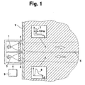
- Figure 1 shows an arrangement with which the visibility in Area in front of a vehicle to be measured.
- the arrangement works according to the well-known LIDAR (Light Detecting and Ranging) principle. It has a transmission element 1 (e.g. an IR laser diode), which from inside the vehicle out through the windshield 2 light pulses into the Area in front of the vehicle, and at least one optical receiving element 3 (e.g. PIN diode), which the the scattering medium in front of the vehicle (e.g. rain, Fog, snow, smoke, etc.) and backscattered light converted into an electrical signal.
- a transmission element 1 e.g. an IR laser diode
- the optical receiving element 3 e.g. PIN diode
- a focusing lens 4 and 5 are arranged to on the one hand, the emitted light spatially limit the limited light beam and on the other hand that backscattered light towards the receiving element 3 focus.
- the spatial limitation of two light rays marked with arrows dashed lines indicated.
- the optical axes of the transmission element 1 and Receiving elements 3 are aligned so that the Transmitting beam and the receiving beam one in FIG. 1 Form cross-hatched overlap area 6.
- the receiving element 3 receives the part of the emitted light, which on the scattering medium, which in FIG diagonal hatching is indicated in the Overlap area 6 is backscattered.
- the transmitting element 1 emits a short Light pulse 7 from about 10 nannoseconds.
- the temporal Course 8 of the light pulse 7 emitted backscattered portion is also in Figure 1 shown.
- the temporal dependence of the amplitude of the backscattered light received by the receiving element 3 directly related to the removal of the Zone of space from which the backscattered light comes.
- each the spatial zone is further away from the receiving element 3, the lower the backscattered portion of the Transmitted light pulse 7, and the shorter the distance Is the spatial zone to the receiving element 7, the higher the this area backscattered part of the transmitted Light pulse 7.
- one Backscatter light curve 8 depending on the distance can record differently distant spatial zones also as described in DE 196 29 712 A1, with several Receiving elements, backscattered light from different spaced-apart spatial zones are included.
- the optical axes of the receiving elements different Angle to the optical axis of the transmission element.
- An evaluation unit 9 is attached to the receiving element 3 connected, which from the output signal of the Backscattering receiving elements 3 die Visibility in the area in front of the vehicle determined.
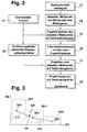
- FIGs 2, 4 and 6 are the flow diagrams of three different methods according to which the Evaluation unit 9 from the output signal of the optical Receiving elements 3 can determine the current visibility.
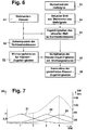
- the visibility class SK1 is e.g. one Visibility of 50m, the visibility class SK2 one Visibility of 100m and the visibility class SK3 one Assigned visibility of 150m.
- the dotted lines Areas limit the range of characteristics of the individual Visibility classes SK1, SK2 and SK3.
- the Visibility classes SK1, SK2, SK3 in a two-dimensional Feature space This means that every measuring point in the feature space of two features M1 and M2 depends. However, every measuring point can even of one characteristic or of more than just two Characteristics depend.
- the individual features M1, M2 either correspond directly to one of several successive samples of the from Receiving element 3 recorded measurement signal 8, or the Features M1, M2 are e.g. through linear combinations or Averaging or scatter calculation or Quotient formation from several samples of a measurement signal educated.
- process step 22 first of all Visibility classes SK1, SK2 and SK3 focus SP1, SP2 and SP3 determined. Then connecting lines V12 and V23 between the focal points SP1, SP2, SP3 der individual visibility classes SK1, SK2 SK3. The points form on the individual connecting lines V12 and V23 practically intermediate values of the visibility between the assigned to individual visibility classes SK1, SK2 and SK3 Visibility (e.g. 50m, 100m, 150m).
- the current visibility measurement which takes place online, takes place now as follows.
- the backscattered light is first measured by the receiving element 3.
- the current Measuring signal calculates one or more characteristics.
- This Features then define a current measuring point.
- the affiliations of this in method step 25 current measuring point for all visibility classes SK1, SK2 and SK3 determined.
- the Method step 27 is a projection of the current one Measuring point on the connecting line.
- Figure 3 illustrates this process.
- There is a current measuring point Marked MP whose highest affiliation in the Visibility class SK2 falls.
- the visibility class SK1 is the one with the second highest affiliation for the Measuring point MP.
- the measuring point MP By projecting the measuring point MP onto the Connection line V12 between these two Visibility classes SK2 and SK1 are obtained Projection point PP on the connecting line V12.
- This Projection point PP now becomes the actual current one Visibility (an intermediate value between the visibility classes SK2 and SK1) assigned.
- a second method for determining the visibility range follows the flow chart shown in Figure 4.
- the visibility ranges SK1, SK2 and SK3 are formed and in Method step 42 focuses on SP1, SP2 and SP3 individual visibility classes SK1, SK2 and SK3 determined.
- Every current measuring process begins with the process step 43, in which the receiving element 3 first Backscattered light is measured.
- Method step 44 features from samples of the Measurement signal derived and a current dependent on it Measuring point determined.
- the affiliations of the current measuring point to all Visibility classes SK1, SK2 and SK3 determined.
- the subsequent method step 46 is, as in the Figure 5 illustrates the distance a of the current measurement point MP compared to the focus SP2 of the visibility class with the highest affiliation determined.
- the distance a represents one Correction value with which the view range class SK2 associated visibility is applied, so as to to get actual visibility.
- the visibility of the Visibility class SK2 with the highest membership for the Measuring point MP increased or decreased by the correction value a must be decided in step 48. A Then the visibility is increased by the correction value a made when the visibility range class with the second largest Affiliation above the visibility class with the highest affiliation.
- the range of vision class SK1 with the second largest affiliation would be the range of vision class SK1 with the second largest affiliation, and this Visibility class SK1 (50m) is below the Visibility class SK2 (100m) with the highest membership. So the visibility range of the visibility range class SK2 would be around to lower the correction value a. An increase in Visibility of the visibility class with the highest Belonging to the correction value a would then have to be made if the visibility range is the second largest Affiliation above the visibility class with the highest affiliation.
- Exactly as in the Process steps 21 and 22 and 41 and 42 are the Visibility classes SK1, SK2 and SK3 and their focus SP1, SP2 and SP3 in process steps 61 and 62 determined.
- the current measuring procedure starts in Method step 63 in turn so that the backscattered light is measured.
- method step 64 features from samples of the measurement signal determined and depending on these characteristics current measuring point determined.
- Method step 65 the affiliations of this current Measuring point determined for all visibility classes.
- the Method step 66 become weighting factors for the Class affiliations formed.
- the continuous visibility measurement described above compared to the rough evaluation in visibility classes Advantage that the visibility measurement results as a manipulated variable for regulated systems can be used in the vehicle which depend on the current visibility. You can do this e.g. Systems that automatically switch the low beam to the Switch fog lights or rear fog lights. Also in Distance control systems can measure the measured visibility be taken into account.
Landscapes
- General Health & Medical Sciences (AREA)
- Health & Medical Sciences (AREA)
- Life Sciences & Earth Sciences (AREA)
- Chemical & Material Sciences (AREA)
- Analytical Chemistry (AREA)
- Biochemistry (AREA)
- Physics & Mathematics (AREA)
- General Physics & Mathematics (AREA)
- Immunology (AREA)
- Pathology (AREA)
- Length Measuring Devices By Optical Means (AREA)
- Investigating Or Analysing Materials By Optical Means (AREA)
- Optical Radar Systems And Details Thereof (AREA)
Abstract
Description
Claims (5)
- Verfahren zur Sichtweitenmessung, insbesondere für Kraftfahrzeuge, wobei in einen Sichtweiten-Meßraum Licht ausgesendet, das im Meßraum rückgestreute Licht gemessen wird und die Zugehörigkeiten des Meßsignals zu mehreren vorgegebenen Sichtweitenklassen ermittelt werden, dadurch gekennzeichnet,daß ein zu jeder Sichtweitenklasse (SK1, SK2, SK3) gehörender Merkmalsbereich, die die Schwerpunkte (SP1, SP2, SP3) der einzelnen Sichtweitenklassen (SK1, SK2, SK3) bildenden Meßpunkte und Meßpunkte, welche die Punkte von Verbindungslinien (V12, V23) zwischen den Schwerpunkten (SP1, SP2, SP3) der aufeinanderfolgenden Sichtweitenklassen (SK1, SK2, SK3) bilden, ermittelt werden, wobei jeder einzelne Meßpunkt von ein oder mehreren Merkmalen (M1, M2) abhängt, die aus ein oder mehreren Abtastwerten eines Referenzmeßsignals abgeleitet sind,daß nach der gleichen Methode wie die Meßpunkte der Sichtweitenklassen (SK1, SK2, SK3) ein von ein oder mehreren Merkmalen (M1, M2) abhängiger aktueller Meßpunkt (MW) gebildet wird, wobei die Merkmale aus ein oder mehreren Abtastwerten eines aktuellen Meßsignals abgeleitet werden,daß vom jeweils aktuell ermittelten Meßpunkt (MP) eine Projektion auf diejenige Verbindungslinie (V12) durchgeführt wird, welche die Schwerpunkte (SP1, SP2, SP3) derjenigen beiden Sichtweitenklassen (SK1, SK2) miteinander verbindet, für die der Meßpunkt (MW) die beiden höchsten Zugehörigkeiten aufweist,und daß dem Projektionspunkt (PP) auf der Verbindungslinie (V12) die tatsächliche aktuelle Sichtweite zugeordnet wird.
- Verfahren zur Sichtweitenmessung, insbesondere für Kraftfahrzeuge, wobei in einen Sichtweiten-Meßraum Licht ausgesendet, das im Meßraum rückgestreute Licht gemessen wird und die Zugehörigkeiten des Meßsignals zu mehreren vorgegebenen Sichtweitenklassen ermittelt werden, dadurch gekennzeichnet,daß der zu jeder Sichtweitenklasse (SK1, SK2, SK3) gehörende Merkmalsbereich und die die Schwerpunkte (SP1, SP2, SP3) der einzelnen Sichtweitenklassen (SK1, SK2, SK3) bildenden Meßpunkte ermittelt werden, wobei jeder einzelne Meßpunkt von ein oder mehreren Merkmalen (M1, M2) abhängt, die aus ein oder mehreren Abtastwerten eines Referenzmeßsignals abgeleitet sind,daß nach der gleichen Methode wie die Meßpunkte der Sichtweitenklassen (SK1, SK2, SK3) ein von ein oder mehreren Merkmalen abhängiger aktueller Meßpunkt (MP) gebildet wird, wobei die Merkmale aus ein oder mehreren Abtastwerten eines aktuellen Meßsignals abgeleitet werden,daß der Abstand (a) zwischen dem jeweils aktuell ermittelten Meßpunkt (MP) und dem Schwerpunkt (SP) derjenigen Sichtweitenklasse (SK2) berechnet wird, für die der aktuelle Meßpunkt (MW) die höchste Zugehörigkeit hat,daß dem ermittelten Abstand (a) ein Korrekturwert zugeordnet wird, um den die Sichtweite der Klasse (SK2) mit der höchsten Zugehörigkeit erhöht oder erniedrigt wird, um somit zu der tatsächlichen Sichtweite zu gelangen,und daß die Sichtweite der Klasse (SK2) mit der höchsten Zugehörigkeit erhöht/erniedrigt wird, wenn die Sichtweitenklasse (SK1) mit der zweitgrößten Zugehörigkeit oberhalb/unterhalb der Sichtweitenklasse (SK2) mit der höchsten Zugehörigkeit liegt.
- Verfahren zur Sichtweitenmessung, insbesondere für Kraftfahrzeuge, wobei in einen Sichtweiten-Meßraum Licht ausgesendet, das im Meßraum rückgestreute Licht gemessen wird und die Zugehörigkeiten des Meßsignals zu mehreren vorgegebenen Sichtweitenklassen ermittelt werden, dadurch gekennzeichnet,daß der zu jeder Sichtweitenklasse (SK1, SK2, SK3) gehörende Merkmalsbereich und die die Schwerpunkte (SP1, SP2, SP3) der einzelnen Sichtweitenklassen (SK1, SK2, SK3) bildenden Meßpunkte ermittelt werden, wobei jeder einzelne Meßpunkt von ein oder mehreren Merkmalen (M1, M2) abhängt, die aus ein oder mehreren Abtastwerten eines Referenzmeßsignals abgeleitet sind,daß nach der gleichen Methode wie die Meßpunkte der Sichtweitenklassen (SK1, SK2, SK3) ein von ein oder mehreren Merkmalen (M1, M2) abhängiger aktueller Meßpunkt (MP) gebildet wird, wobei die Merkmale aus ein oder mehreren Abtastwerten eines aktuellen Meßsignals abgeleitet werden,daß die für den jeweils aktuellen erfaßten Meßpunkt (MP) ermittelten Zugehörigkeiten (ZG) zu allen Sichtweitenklassen mit Wichtungsfaktoren multipliziert werden,daß die Wichtungsfaktoren so gewählt werden, daß bei einer Multiplikation der Zugehörigkeiten (ZG) eines in den Schwerpunkt einer Sichtweitenklasse fallenden aktuellen Meßpunktes (MP) und nach anschließender Summation der Gewichtzugehörigkeiten (ZG) eine Sichtweite resultiert, die gleich der Sichtweitenklasse ist,und daß aus allen gewichteten Zugehörigkeiten eine Summe gebildet wird, welche dann als aktuelle Sichtweite angenommen wird.
- Verfahren nach einem der Ansprüche 1, 2 oder 3, dadurch gekennzeichnet, daß die Merkmale (M1, M2) durch Linearkombination oder Mittelwertbildung oder Quotientenbildung oder Streuungsberechnung von mehreren Meßsignal-Abtastwerten entstehen.
- Verfahren nach einem der Ansprüche 1, 2 oder 3, dadurch gekennzeichnet, daß jedes Merkmal (M1, M2) einem Meßsignal-Abtastwert entspricht.
Applications Claiming Priority (2)
| Application Number | Priority Date | Filing Date | Title |
|---|---|---|---|
| DE1999155249 DE19955249A1 (de) | 1999-11-17 | 1999-11-17 | Verfahren zur Sichtweitenmessung |
| DE19955249 | 1999-11-17 |
Publications (3)
| Publication Number | Publication Date |
|---|---|
| EP1103418A2 true EP1103418A2 (de) | 2001-05-30 |
| EP1103418A3 EP1103418A3 (de) | 2001-10-17 |
| EP1103418B1 EP1103418B1 (de) | 2007-01-17 |
Family
ID=7929317
Family Applications (1)
| Application Number | Title | Priority Date | Filing Date |
|---|---|---|---|
| EP20000124797 Expired - Lifetime EP1103418B1 (de) | 1999-11-17 | 2000-11-14 | Verfahren zur Sichtweitenmessung |
Country Status (3)
| Country | Link |
|---|---|
| EP (1) | EP1103418B1 (de) |
| DE (2) | DE19955249A1 (de) |
| ES (1) | ES2278569T3 (de) |
Cited By (1)
| Publication number | Priority date | Publication date | Assignee | Title |
|---|---|---|---|---|
| DE102004004190A1 (de) * | 2004-01-28 | 2005-08-25 | Opel Eisenach Gmbh | Kraftfahrzeug mit einer Nebelschlussleuchte und einem Fahrassistenzsystem |
Families Citing this family (5)
| Publication number | Priority date | Publication date | Assignee | Title |
|---|---|---|---|---|
| DE10137818C1 (de) * | 2001-08-02 | 2003-04-10 | Daimler Chrysler Ag | Vorrichtung und Verfahren zum adaptiven Betreiben einer Nebelschlussleuchte |
| DE10149768A1 (de) * | 2001-10-09 | 2003-04-17 | Ibeo Automobile Sensor Gmbh | Sichtweitenbestimmung |
| DE102009057982B4 (de) | 2009-12-11 | 2024-01-04 | Bayerische Motoren Werke Aktiengesellschaft | Verfahren zur Wiedergabe der Wahrnehmbarkeit eines Fahrzeugs |
| DE102013102608A1 (de) * | 2013-03-14 | 2014-09-18 | Audi Ag | Kollisionsschutzvorrichtung für eine schwenkbare Klappe eines Kraftfahrzeugs, Klappe, Kraftfahrzeug und entsprechendes Verfahren |
| DE102019208762A1 (de) * | 2019-06-17 | 2020-12-17 | Conti Temic Microelectronic Gmbh | Verfahren zur Steuerung von Fahrzeugscheinwerfern |
Family Cites Families (3)
| Publication number | Priority date | Publication date | Assignee | Title |
|---|---|---|---|---|
| US3782824A (en) * | 1972-06-01 | 1974-01-01 | Sperry Rand Corp | Apparatus and method for measuring extinction coefficient of an atmospheric scattering medium |
| DE4016973C1 (de) * | 1990-02-24 | 1991-06-13 | Eltro Gmbh, Gesellschaft Fuer Strahlungstechnik, 6900 Heidelberg, De | |
| DE19629712A1 (de) * | 1996-07-25 | 1998-01-29 | Bosch Gmbh Robert | Verfahren und Vorrichtung zur Sichtweitenmessung |
-
1999
- 1999-11-17 DE DE1999155249 patent/DE19955249A1/de not_active Withdrawn
-
2000
- 2000-11-14 DE DE50013971T patent/DE50013971D1/de not_active Expired - Lifetime
- 2000-11-14 EP EP20000124797 patent/EP1103418B1/de not_active Expired - Lifetime
- 2000-11-14 ES ES00124797T patent/ES2278569T3/es not_active Expired - Lifetime
Cited By (1)
| Publication number | Priority date | Publication date | Assignee | Title |
|---|---|---|---|---|
| DE102004004190A1 (de) * | 2004-01-28 | 2005-08-25 | Opel Eisenach Gmbh | Kraftfahrzeug mit einer Nebelschlussleuchte und einem Fahrassistenzsystem |
Also Published As
| Publication number | Publication date |
|---|---|
| ES2278569T3 (es) | 2007-08-16 |
| EP1103418A3 (de) | 2001-10-17 |
| DE50013971D1 (de) | 2007-03-08 |
| EP1103418B1 (de) | 2007-01-17 |
| DE19955249A1 (de) | 2001-05-23 |
Similar Documents
| Publication | Publication Date | Title |
|---|---|---|
| EP1816488B1 (de) | Optoelektronische Vorrichtung und Verfahren zu deren Betrieb | |
| EP0691534B1 (de) | Verfahren zur Ermittlung der Sichtweite, insbesondere für die Bewegung eines Kraftfahrzeuges | |
| DE19531632B4 (de) | Entfernungsmeßgerät | |
| EP1303768B1 (de) | Verfahren zur sichtweitenbestimmung | |
| EP1067399A2 (de) | Verfahren zur Sichtweitenbestimmung | |
| EP1405037A1 (de) | Vorrichtung zur optischen distanzmessung über einen grossen messbereich | |
| EP1953504A1 (de) | Verfahren zur Erfassung eines Gegenstands und optoelektronische Vorrichtung | |
| EP2824478A1 (de) | Optoelektronischer Sensor und Verfahren zur Erfassung und Abstandsbestimmung von Objekten in einem Überwachungsbereich | |
| DE3816392A1 (de) | Verfahren zur bestimmung der optischen qualitaet von flachglas oder flachglasprodukten | |
| EP1531342A1 (de) | Verfahren zur Erkennung von Fussgängern | |
| DE102020115145A1 (de) | Punktwolkenverarbeitung | |
| DE102020206006A1 (de) | Verfahren zum Kalibrieren und/oder Justieren und Steuereinheit für ein LiDAR-System, LiDAR-System und Arbeitsvorrichtung | |
| DE102015217912A1 (de) | Verfahren zur Laufzeitkalibrierung eines Lidarsensors | |
| EP1157288A1 (de) | Vorrichtung zur sichtweitenmessung | |
| DE10011890C2 (de) | Verfahren zur Bestimmung der Zustandsgrössen eines sich bewegenden starren Körpers im Raum | |
| EP3663881B1 (de) | Verfahren zur steuerung eines autonomen fahrzeugs auf der grundlage von geschätzten bewegungsvektoren | |
| EP1103418B1 (de) | Verfahren zur Sichtweitenmessung | |
| EP1504285B1 (de) | Verfahren und vorrichtung zur sichtweitenmessung mit bildsensorsystemen | |
| DE69803044T2 (de) | Optisches gerät zur kontaktlosen messung des abstandes zu einer lichtquelle | |
| EP1695109A1 (de) | Vorrichtung zum messen der distanz zu fernen und nahen objekten | |
| DE2450439A1 (de) | Einrichtungen zur beruehrungslosen messung der geschwindigkeit | |
| DE602004003912T2 (de) | Vorrichtung und Verfahren zur Messung der Sichtweite | |
| EP4310548A2 (de) | Vorrichtung und verfahren zur überwachung einer fahrbahn | |
| EP0674184A1 (de) | Verfahren und Vorrichtung zur Klassifizierung von Fahrzeugen mittels eines Verkehrsradargerätes | |
| EP4279946A1 (de) | Sensor und verfahren zur detektion von objekten mittels eines sensors |
Legal Events
| Date | Code | Title | Description |
|---|---|---|---|
| PUAI | Public reference made under article 153(3) epc to a published international application that has entered the european phase |
Free format text: ORIGINAL CODE: 0009012 |
|
| AK | Designated contracting states |
Kind code of ref document: A2 Designated state(s): AT BE CH CY DE DK ES FI FR GB GR IE IT LI LU MC NL PT SE TR Kind code of ref document: A2 Designated state(s): DE ES FR GB IT |
|
| AX | Request for extension of the european patent |
Free format text: AL;LT;LV;MK;RO;SI |
|
| PUAL | Search report despatched |
Free format text: ORIGINAL CODE: 0009013 |
|
| AK | Designated contracting states |
Kind code of ref document: A3 Designated state(s): AT BE CH CY DE DK ES FI FR GB GR IE IT LI LU MC NL PT SE TR |
|
| AX | Request for extension of the european patent |
Free format text: AL;LT;LV;MK;RO;SI |
|
| 17P | Request for examination filed |
Effective date: 20020417 |
|
| AKX | Designation fees paid |
Free format text: DE ES FR GB IT |
|
| GRAP | Despatch of communication of intention to grant a patent |
Free format text: ORIGINAL CODE: EPIDOSNIGR1 |
|
| GRAS | Grant fee paid |
Free format text: ORIGINAL CODE: EPIDOSNIGR3 |
|
| GRAA | (expected) grant |
Free format text: ORIGINAL CODE: 0009210 |
|
| AK | Designated contracting states |
Kind code of ref document: B1 Designated state(s): DE ES FR GB IT |
|
| REG | Reference to a national code |
Ref country code: GB Ref legal event code: FG4D Free format text: NOT ENGLISH |
|
| REF | Corresponds to: |
Ref document number: 50013971 Country of ref document: DE Date of ref document: 20070308 Kind code of ref document: P |
|
| GBT | Gb: translation of ep patent filed (gb section 77(6)(a)/1977) |
Effective date: 20070412 |
|
| ET | Fr: translation filed | ||
| REG | Reference to a national code |
Ref country code: ES Ref legal event code: FG2A Ref document number: 2278569 Country of ref document: ES Kind code of ref document: T3 |
|
| PLBE | No opposition filed within time limit |
Free format text: ORIGINAL CODE: 0009261 |
|
| STAA | Information on the status of an ep patent application or granted ep patent |
Free format text: STATUS: NO OPPOSITION FILED WITHIN TIME LIMIT |
|
| 26N | No opposition filed |
Effective date: 20071018 |
|
| PGFP | Annual fee paid to national office [announced via postgrant information from national office to epo] |
Ref country code: ES Payment date: 20091123 Year of fee payment: 10 |
|
| PGFP | Annual fee paid to national office [announced via postgrant information from national office to epo] |
Ref country code: GB Payment date: 20091123 Year of fee payment: 10 Ref country code: IT Payment date: 20091130 Year of fee payment: 10 Ref country code: FR Payment date: 20091202 Year of fee payment: 10 |
|
| PGFP | Annual fee paid to national office [announced via postgrant information from national office to epo] |
Ref country code: DE Payment date: 20100121 Year of fee payment: 10 |
|
| GBPC | Gb: european patent ceased through non-payment of renewal fee |
Effective date: 20101114 |
|
| REG | Reference to a national code |
Ref country code: FR Ref legal event code: ST Effective date: 20110801 |
|
| REG | Reference to a national code |
Ref country code: DE Ref legal event code: R119 Ref document number: 50013971 Country of ref document: DE Effective date: 20110601 Ref country code: DE Ref legal event code: R119 Ref document number: 50013971 Country of ref document: DE Effective date: 20110531 |
|
| PG25 | Lapsed in a contracting state [announced via postgrant information from national office to epo] |
Ref country code: DE Free format text: LAPSE BECAUSE OF NON-PAYMENT OF DUE FEES Effective date: 20110531 |
|
| PG25 | Lapsed in a contracting state [announced via postgrant information from national office to epo] |
Ref country code: FR Free format text: LAPSE BECAUSE OF NON-PAYMENT OF DUE FEES Effective date: 20101130 |
|
| PG25 | Lapsed in a contracting state [announced via postgrant information from national office to epo] |
Ref country code: GB Free format text: LAPSE BECAUSE OF NON-PAYMENT OF DUE FEES Effective date: 20101114 |
|
| PG25 | Lapsed in a contracting state [announced via postgrant information from national office to epo] |
Ref country code: IT Free format text: LAPSE BECAUSE OF NON-PAYMENT OF DUE FEES Effective date: 20101114 |
|
| REG | Reference to a national code |
Ref country code: ES Ref legal event code: FD2A Effective date: 20120110 |
|
| PG25 | Lapsed in a contracting state [announced via postgrant information from national office to epo] |
Ref country code: ES Free format text: LAPSE BECAUSE OF NON-PAYMENT OF DUE FEES Effective date: 20101115 |