EP1103790A2 - Bewegungsdetektion und Analyse - Google Patents
Bewegungsdetektion und Analyse Download PDFInfo
- Publication number
- EP1103790A2 EP1103790A2 EP00310355A EP00310355A EP1103790A2 EP 1103790 A2 EP1103790 A2 EP 1103790A2 EP 00310355 A EP00310355 A EP 00310355A EP 00310355 A EP00310355 A EP 00310355A EP 1103790 A2 EP1103790 A2 EP 1103790A2
- Authority
- EP
- European Patent Office
- Prior art keywords
- signals
- processing
- movement
- axes
- coordinate axis
- Prior art date
- Legal status (The legal status is an assumption and is not a legal conclusion. Google has not performed a legal analysis and makes no representation as to the accuracy of the status listed.)
- Withdrawn
Links
- 238000004458 analytical method Methods 0.000 title description 11
- 238000001514 detection method Methods 0.000 title description 8
- 230000008859 change Effects 0.000 claims abstract description 78
- 238000005070 sampling Methods 0.000 claims abstract description 22
- 238000005259 measurement Methods 0.000 claims description 110
- 238000012545 processing Methods 0.000 claims description 67
- 238000001914 filtration Methods 0.000 claims description 21
- 238000000034 method Methods 0.000 claims description 19
- 230000001133 acceleration Effects 0.000 claims description 18
- 238000012544 monitoring process Methods 0.000 claims description 3
- 238000000926 separation method Methods 0.000 claims description 3
- 238000006073 displacement reaction Methods 0.000 description 15
- 238000010586 diagram Methods 0.000 description 8
- 230000006870 function Effects 0.000 description 7
- 239000000872 buffer Substances 0.000 description 5
- 230000007423 decrease Effects 0.000 description 5
- 230000008569 process Effects 0.000 description 5
- 238000013459 approach Methods 0.000 description 4
- 230000008901 benefit Effects 0.000 description 4
- 230000007704 transition Effects 0.000 description 4
- 238000011161 development Methods 0.000 description 3
- 230000003068 static effect Effects 0.000 description 3
- 230000003044 adaptive effect Effects 0.000 description 2
- 239000003990 capacitor Substances 0.000 description 2
- 230000000694 effects Effects 0.000 description 2
- 230000004048 modification Effects 0.000 description 2
- 238000012986 modification Methods 0.000 description 2
- 230000009467 reduction Effects 0.000 description 2
- 230000004044 response Effects 0.000 description 2
- 230000009471 action Effects 0.000 description 1
- 238000004364 calculation method Methods 0.000 description 1
- 238000006243 chemical reaction Methods 0.000 description 1
- 239000002131 composite material Substances 0.000 description 1
- 239000012141 concentrate Substances 0.000 description 1
- 238000010276 construction Methods 0.000 description 1
- 230000036461 convulsion Effects 0.000 description 1
- 238000009795 derivation Methods 0.000 description 1
- 238000013461 design Methods 0.000 description 1
- 230000006872 improvement Effects 0.000 description 1
- 238000005305 interferometry Methods 0.000 description 1
- 230000001151 other effect Effects 0.000 description 1
- 230000000737 periodic effect Effects 0.000 description 1
- 239000004065 semiconductor Substances 0.000 description 1
Images







Classifications
-
- G—PHYSICS
- G01—MEASURING; TESTING
- G01D—MEASURING NOT SPECIALLY ADAPTED FOR A SPECIFIC VARIABLE; ARRANGEMENTS FOR MEASURING TWO OR MORE VARIABLES NOT COVERED IN A SINGLE OTHER SUBCLASS; TARIFF METERING APPARATUS; MEASURING OR TESTING NOT OTHERWISE PROVIDED FOR
- G01D5/00—Mechanical means for transferring the output of a sensing member; Means for converting the output of a sensing member to another variable where the form or nature of the sensing member does not constrain the means for converting; Transducers not specially adapted for a specific variable
- G01D5/12—Mechanical means for transferring the output of a sensing member; Means for converting the output of a sensing member to another variable where the form or nature of the sensing member does not constrain the means for converting; Transducers not specially adapted for a specific variable using electric or magnetic means
- G01D5/244—Mechanical means for transferring the output of a sensing member; Means for converting the output of a sensing member to another variable where the form or nature of the sensing member does not constrain the means for converting; Transducers not specially adapted for a specific variable using electric or magnetic means influencing characteristics of pulses or pulse trains; generating pulses or pulse trains
- G01D5/24471—Error correction
- G01D5/24476—Signal processing
-
- G—PHYSICS
- G01—MEASURING; TESTING
- G01D—MEASURING NOT SPECIALLY ADAPTED FOR A SPECIFIC VARIABLE; ARRANGEMENTS FOR MEASURING TWO OR MORE VARIABLES NOT COVERED IN A SINGLE OTHER SUBCLASS; TARIFF METERING APPARATUS; MEASURING OR TESTING NOT OTHERWISE PROVIDED FOR
- G01D5/00—Mechanical means for transferring the output of a sensing member; Means for converting the output of a sensing member to another variable where the form or nature of the sensing member does not constrain the means for converting; Transducers not specially adapted for a specific variable
- G01D5/12—Mechanical means for transferring the output of a sensing member; Means for converting the output of a sensing member to another variable where the form or nature of the sensing member does not constrain the means for converting; Transducers not specially adapted for a specific variable using electric or magnetic means
- G01D5/244—Mechanical means for transferring the output of a sensing member; Means for converting the output of a sensing member to another variable where the form or nature of the sensing member does not constrain the means for converting; Transducers not specially adapted for a specific variable using electric or magnetic means influencing characteristics of pulses or pulse trains; generating pulses or pulse trains
- G01D5/245—Mechanical means for transferring the output of a sensing member; Means for converting the output of a sensing member to another variable where the form or nature of the sensing member does not constrain the means for converting; Transducers not specially adapted for a specific variable using electric or magnetic means influencing characteristics of pulses or pulse trains; generating pulses or pulse trains using a variable number of pulses in a train
- G01D5/2451—Incremental encoders
-
- G—PHYSICS
- G01—MEASURING; TESTING
- G01D—MEASURING NOT SPECIALLY ADAPTED FOR A SPECIFIC VARIABLE; ARRANGEMENTS FOR MEASURING TWO OR MORE VARIABLES NOT COVERED IN A SINGLE OTHER SUBCLASS; TARIFF METERING APPARATUS; MEASURING OR TESTING NOT OTHERWISE PROVIDED FOR
- G01D5/00—Mechanical means for transferring the output of a sensing member; Means for converting the output of a sensing member to another variable where the form or nature of the sensing member does not constrain the means for converting; Transducers not specially adapted for a specific variable
- G01D5/26—Mechanical means for transferring the output of a sensing member; Means for converting the output of a sensing member to another variable where the form or nature of the sensing member does not constrain the means for converting; Transducers not specially adapted for a specific variable characterised by optical transfer means, i.e. using infrared, visible, or ultraviolet light
- G01D5/32—Mechanical means for transferring the output of a sensing member; Means for converting the output of a sensing member to another variable where the form or nature of the sensing member does not constrain the means for converting; Transducers not specially adapted for a specific variable characterised by optical transfer means, i.e. using infrared, visible, or ultraviolet light with attenuation or whole or partial obturation of beams of light
- G01D5/34—Mechanical means for transferring the output of a sensing member; Means for converting the output of a sensing member to another variable where the form or nature of the sensing member does not constrain the means for converting; Transducers not specially adapted for a specific variable characterised by optical transfer means, i.e. using infrared, visible, or ultraviolet light with attenuation or whole or partial obturation of beams of light the beams of light being detected by photocells
- G01D5/36—Forming the light into pulses
Definitions
- the present invention relates to the detection and analysis of motion. It is particularly, but not exclusively, concerned with detection of motion measured by interferometer or encoder systems.
- the simplest case is where there are two sensors which differ by 90° in phase, for example one producing a sine output whilst the other producing a cosine output. If these are presented on mutually orthogonal axes, the possible outputs can be considered as being within a detection circle centred on the origin of the coordinate axes.
- That coordinate system may represent displacement
- a given point within the circle may be represented by two polar coordinates: angle and radius.
- the radius is a measure of the magnitude of the signal strength, and the angle is a measure of displacement.
- the angular ordinate increases or decreases the displacement measured by the system increases or decreases.
- the displacement resolution of the system is limited by the precision to which the angular ordinate can be measured.
- the signals are sensed at periodic time intervals.
- the value obtained at any sensing point will be somewhere within the detection circle.
- the circle To be divided into 90° segments. In conventional systems the current position (angular segment) is compared with the previous position. There are four possible answers. If the segmental difference is zero, then the system assumes that the system has remained "stationary”. If the difference is plus one then the system assumes that the displacement has positively increased, and if the difference is minus one then the system assumes that the displacement has negatively increased. Finally if the difference is either +2 or -2 then system flags an over speed error since the system cannot decide whether the system has moved in the positive or negative direction.
- the present invention seeks to overcome the over speed problem even when the sampling rate is below the analogue bandwidth, and to make the system less susceptible to noise.
- the present invention proposes that the analysis of two signals, preferably in quadrature (sine and cosine signals), is on the basis of a high resolution coordinate axis system, or at least two independent systems of coordinate axes, which are rotationally displaced.
- the minimum requirement is that the coordinate system is split into at least six sextants. Where there are multiple coordinate axis systems, the requirement for at least six segments represents the requirement for the total number of segments from all systems added together.
- velocity constraint is represented by the number of segments jumped between clock samples.
- maximum velocity in a four quadrant system is ⁇ 1
- a jump of two segments would flag an over speed error
- the maximum velocity would be ⁇ 2 since a jump of three would flag an over speed error.
- this limitation is removed, but in the simplest implementation of the invention the change in velocity (i.e. acceleration) between clock samples is restricted to 0, ⁇ 1 and ⁇ 2.
- this invention considers constraints on change in velocity, or change in acceleration, or higher derivative rather than the change in displacement. Constraining the change in velocity needs three measurements, whilst constraining the change in acceleration needs four.
- the velocity difference between the first and second measurement is zero, and hence is a valid measurement.
- the velocity difference between the second and third measurement is +1, and hence also represents a valid measurement.
- the velocity difference between the third and fourth measurement is 2, and hence is valid, but if the system was being analysed by the traditional method this movement is a jump of three segments and hence would represent an invalid move, and hence the maximum constraint on velocity has been lifted.
- a first coordinate axis system defines two axes at 90°, thereby defining four quadrants, and a second axis system again has two axes at 90°, but those axes being at 45° to the axes of the first system.
- each axis system may be defined by each axis system, and preferably, have a common centre.
- the quantity being measured is displacement, and it is a constraint on the system that satisfactory movement can only result in a change no greater than from one segment to an adjacent one. Movements through two segments are not permitted.
- a first measurement (assumed to be valid) is necessarily within a segment in each of the two coordinate axes.
- the second measurement may be in a segment adjacent to the first in one coordinate system, but in the same segment in the second. This is clearly a valid measurement.
- the measurement point changes to an adjacent segment in both coordinate systems, again it is valid. If the measurement has changed by two segments in one coordinate system, but only one in another, then it is of doubtful validity, and if it changes by two segments in both coordinate systems it is clearly invalid, and in this case the system would flag an over speed error.
- arrangements involving two or more coordinate axis systems are not limited to the situation where the two (or more) coordinate axis systems have the same number of axes. They may by different, although they preferably should not be multibly of each other, and have no common factors. Where there are two axis systems, suitable axis ratios include 4:7, 3:8, 5:8 and 7:8. Moreover, in such arrangements where the number of axes of the two (or more)coordinate axis systems are different, it is possible for one or more axes of one coordinate system to coincide with one or more axes of another axis system.
- the present invention may also provide an apparatus for determining movement, comprising means for generating at least two signals of different phase in dependence on the relative position of two objects, movement of said two objects causing corresponding changes in said at least two signals; thereby to determine said movement, the processing by said processing means being on the basis of locating the constellation states of successive values of the at least two signals in at least first and second coordinate axis systems, said at least first and second coordinate axis systems each defining at least three separate segments rotationally displaced, and said processing means is arranged to monitor the change in said constellation states of the successive values by using at least three processed data samples, said successive samples being obtained by sampling said at least two signals at a predetermined clock rate.
- the first change may be from one segment to another (a velocity change of +1), the second change being two segments (a velocity change from 1 to 2) etc. It can be noted that if the velocity has incremented this way to a value of 2, the next measurement not valid would be in the same segment. Since that would now represent a change to velocity 0 or to velocity 4, hence a decrease of 2 or an increase of 2, which is outside the constraints required. More generally, the constraint may be that the quantity under consideration may only change by ⁇ 1 or 0. The constraint may be velocity, but could also be acceleration or jerk (rate of change of acceleration). The position of constraints represents development of the present invention as previously defined.
- the constraint of ⁇ 1 can be raised. For example if the circle is divided into 8 segments instead of 4 then the maximum constraint would be ⁇ 3, although in practice one may wish to reduce it to ⁇ 2.
- the above description assumed that the first measurement is a static one. Again, the invention is not limited to this, and it would be possible for that first measurement to represent movement. If previous velocity information was available, earlier measurements may be provided by means other than use of system processing. Nevertheless, two measurements are needed to start the system, since even in the static case two measurements are needed to establish that the object is static, so that is why three samples are needed.
- the former can then be assumed to be a valid measurement affected by noise, and the measurement treated as if it is in a valid segment, whereas the latter can be treated as an invalid measurement.
- This can be generalised by dividing the angular separation (normally 45°) of adjacent axes from the two coordinate systems into two parts of angular width X and Y with measurements within angular width X considered valid and measurements within angular width Y being considered invalid. The ratio of X and Y may then be varied to adjust the acceptable noise level. This ability to adjust what is treated as valid and what is treated as invalid will be referred to as 'soft error'.
- the present invention may permit the detection of over speed in a situation where any individual measurement is affected by noise, and it is possible to allow for measurements which could represent over speed, or could represent measurements represented by noise. It is then possible to adjust the levels of acceptable noise/levels of invalidity acceptable.
- the present invention is applicable to velocities up to that sampling rate.
- the present invention permits predictions to be made on the basis of previous measurements.
- the processing means referred to previously may then be arranged to derive a prediction of one of the successive values of the constellation states from at least three of the earlier values of constellation states, and to compare that prediction with the corresponding location of the constellation state as subsequently measured.
- This idea may be developed further into an adjustable filtering system with an adjustable centre frequency, and possibly bandwidth, of the bandpass filter which varies in dependence on values of the signals representing motion. Whilst this may involve the use of one or more coordinate axis systems as previously mentioned, other arrangements are also possible to derive a prediction of the signal value and hence this represents an independent aspect of the present invention.
- the present invention may provide an apparatus for determines movement, comprising:
- each of these aspects also includes a method of determining movement forming the processing steps carried out by the apparatus.
- Fig 1 also shows that the output of the processor 107 is passed via a counter 108 to a suitable output device 109 such as a display unit or servo controller. It should be noted that the device thus described may be modified eg by use of a single analogue to digital converter which switches between the outputs of the amplifiers 102 and 105.
- FIG. 2 shows the outputs of two sensors producing sine and cosine outputs, measured against a single axes systems.
- Fig 2 shows an axes system defined by axes A, B, C and D which are successively spaced at 90° about a common centre.
- lines A', B', C' and D' are also spaced at 90° about that common centre, being spaced at 45° relative to axes A, B, C and D.
- These axes and lines define 8 segments and are labelled 1 to 8.
- This system can be thought of as a single axis system with eight axes.
- the constellation of states of the sine and cosine signals from amplifiers 105 and 106 are represented by the circle 9.
- the first measured value is at point 10. That is in segment 1. If the second measured point is at point 11, then that point is within the same segment, and hence represents a "stationary" move, and hence is valid. If the third measured point is at point 12, within segment 2, then this represents a move from segment 1 to segment 2, and represents a valid move with velocity 1. If the third measured point was at point 13 as opposed to point 12, then this represents a move from segment 1 to segment 3, and represents a valid move with velocity 2. If the third measured point is at point 14, then this represents a move from segment 1 to segment 4, and represents a move with velocity 3. Depending on the system characteristics this could represent a valid move.
- the problem with this approach is one of noise. If the change in velocity constraint is ⁇ 3, then this implies that the noise in the system needs to be significant less than an octant to avoid false error flags.
- the system can be considered as two separate systems of four segments each, with their axis rotated by 45°.
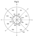
- FIG 3 shows the outputs of two sensors producing sine and cosine outputs, measured against two axes systems.
- Fig 3 shows the first axes system defined by axis A, B, C and D which are successively spaced at 90° about a common centre.
- axes A', B', C' and D' are also spaced at 90° about that common centre, being spaced by 45° relative to axes A, B, C and D.
- four 90° segments are defined, with the axes A, B, C and D defining segments 301 to 304, and axes A', B', C' and D' defining segments 305 to 308.
- the constellation states of the sine and cosine signals from the amplifiers 102, 105 in Fig 1 may be represented by circle 309.
- any valid change in measured value must lie in the same segment as, or in a segment which is adjacent to, the segment containing the first measured value.
- the first measured value is at point 310. That is in segments 301 and 305 in the two axes systems. If the second measured point is at point 311, then that is still within segment 301 but represents a move from segment 305 to segment 306. Since changes of one segment are valid, this is a valid measurement. Similarly, if the second measured point is at point 312, then this represents a movement from segments 302 and 306 from segments 301 and 305, which again is valid. However, if the next measurement after point 310 is at point 313, then this is in segments 302 and 307. So far as the change between segments 301 and 302 is concerned, this is valid. However, the change from segments 305 to 307 is invalid, and thus this measurement is of doubtful validity. If the next measurement from measurement point 310 is at point 314, then this represents a movement to segments 303 and 307, which is invalid in both axes systems.
- the process can be considered in the opposite direction for points 317, 316 and 315, and it can be appreciated that the measurement sequence 310, 311, 312, 313, 314, 315, 316, 317, 310 is valid, as is the sequence 310, 312, 314, 316, 310. Indeed, the sequence 310, 311, 313, 314, 316, 310 is also valid since the change from 311 to 313 represents a change to segments 302 and 307 from segments 301 and 306, and is therefore also a valid change.
- the difference between using two sets of axes, and using one set with smaller angles between the axes is similar. However, this does not take into account the issue of noise. Any measurement has uncertainty, as it may be subject to noise and other inaccuracies.
- the first measurement point is at point 310, and the second is at point 313. If noise is a factor, the actual value may be displaced from that point and indeed could be on the opposite side of axis B', in which case it would be valid, or the opposite side of axis C, in which case it would be clearly invalid.
- Measurements point 316 and 317 are invalid (no change in one or both systems) and valid measurements are at point 310 (one change in both) 312 and 314. If it were at 314, representing an increase in velocity, then the next valid measurement points after that requires changes of 2, 3 or 4 segments, so now measurement points 310, 312 and 314 would again be valid.
- Fig 1 enables the processing of Fig 3 to be carried out using digital electronics which has a loop update rate which can be slower than the response time of the analogue response time.
- the analogue to digital converters 103, 106 need to have a narrow sampling time compared to the clock sampling time. Then, when they sample the signals input from the amplifiers 102, 105, the part of the signal sampled represents only a small part of the analogue cycle. They thus provide useful sampling effects. If the sampling time is of the order of the period of the analogue cycle, then no useful results would be obtained in the arrangement of Fig 1.
- each measurement point moves from one quadrant to another, through four possible segments (quadrants) in each axis system.
- this may be achieved by defining four pointers with successive values.
- the constraint on the system of a change of ⁇ 1 or 0 represents a change from a pointer value to an adjacent pointer value, or remaining at the same pointer value.
- the value represented by the pointer may be velocity, etc as previously mentioned.
- the detection of over speed error has been done by comparing the current result with the previous result.
- An alternative, more desirable method is to use the pointer system in a predictive mode. In this case one uses the pointer system to predict in which segment the next measurement should be, and the comparison is made between the actual segment and the predicted segment.
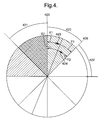
- Fig 4 is similar to Fig 3, but this discussion concentrates on a 45° segment 420 which represents a doubtful measurement, in the sense that it represents a movement which is valid in one axis system and invalid in the other. That 45° segment 420 has, on either side of it, a 45° segment 421 which is valid in both axis systems, and a 45° segment 422 which represents an invalid measurement in both axis systems. Note that, in Fig 4, it is assumed that the movement is counter-clockwise.
- Measurement point 423 is separated by a distance X1 from the axis 425 separating segments 420 and 421, and separated by a distance Y1 from the axis 426 separating segments 420 and 422.
- measurement point 424 is separated from axis 425 by distance X2 and is separated from axis 426 by distance Y2. Then, since X1 is less than Y1, measurement point 423 is closer to the valid segment 421 than the invalid segment 422 and so can be considered valid. Measurement point 424 is closer to the invalid segment 422, than the valid segment 421 and therefore may be considered invalid.
- This approach may be generalised so that if a measurement point is separated by angular distance X from the axes marking the boundary of the valid segment, and separated by angular distance Y from the boundary marking an invalid segment, then the decision as to whether to accept the measurement or not depends on the ratio of X to Y.
- the ratio can be chosen by the system designer, based on how much noise can be tolerated and how quickly a condition which corresponds to an error in the operation needs to be to detected. It should be noted that making use of this feature requires the analogue to digital convertors 103, 106 to define at least 16 different states, but in practice this is not a problem.
- Fig 5 is a block diagram illustrating the processing that has thus been described. In Fig 5, it is assumed that the soft error decision is made when X and Y are equal.
- a sample value received at block 200 is first processed by blocks 201, 202, 203 and 204 to define the position of the sample in the two coordinate systems illustrated by Fig 3. Having determined the position of the measurement point, the actual measurement in one axis system is compared at block 205 with the predicted value in that axis system derived from a buffer 206. The predicted value derived from the buffer 206 is derived on the basis of previous measurements as has previously been discussed. If the two are the same, then the velocity of the object is uniform and this is within the constraints of velocity changes of ⁇ 1 or 0 which have been set. Processing then moves via block 207 to block 208 in which the actions of block 205 are repeated in the second coordinate system.
- processing moves via block 209 to blocks 210, 211 in which the predicted values are updated and the position of the object updated in block 212.
- the measurement procedure then ends for that sample at block 213, and the process is then repeated for the next sample.
- block 218 identifies that the soft error is greater than the permitted limit, an error is identified at block 220. From block 218, there are again several possibilities, as for block 208. If the difference between the actual and predicted values is 0, processing moves via blocks 221 and 222, which correspond to blocks 209 and 211 to block 223 in which the values in the two coordinate systems are compared to enable the system to determine whether the change is positive or negative. Processing then moves via blocks 224 or 225 (one positive, one negative) to blocks 226 and 227, which correspond to blocks 210 and 212, and processing then ends at block 213.
- processing moves to block 229 which performs a similar soft error function to block 217.
- processing immediately moves to block 220. If it is within acceptable limits (note that the sign of the values is now the opposite to that of block 217, processing moves to block 230 in which the same comparison is carried out as block 223 to derive new values at blocks 231 or 232 in a similar way to blocks 225 and 224. Processing then moves back to block 210.
- the actual and predicted values are acceptable in both coordinate systems, the buffers are updated, the values of position updated, and the measurement cycle ends. If either is outside the permitted limit, then soft error measurements are made. If either of those gives an unacceptable result, or if the actual and predicted values in both coordinate systems are unacceptable, then this is treated as an error. If one or other of the soft error functions gives an acceptable result, then it is assumed that the system has been effected by noise and processing continues.
- the two coordinate axis systems have the same number of axes, with the axes of one system being rotationally displaced relative to the axes.
- Fig. 6 illustrates an embodiment in which the coordinate axis systems have different numbers of axes.
- one system has four axes A, B, C and D which are successively displaced by 90° about a common centre, and thus are equivalent to one of the axis systems in Fig. 3.
- four 90° segments 500 to 503 are defined in which the constellation states of the sine and cosine signals are within.
- the second axis system is defined by axes E', F', G', H', I', J' and K' illustrated by dotted lines in Fig. 6, defining seven segments 501 to 511. Note that, for the sake of clarity, the periphery 512 of the segments 500 to 503 is shown spaced from the periphery 513 of segments 505 to 511, but this is not necessary in a practical embodiment. In this arrangement, the axes A and E' coincide, although again this is not essential.
- the number of axes in the two axis systems can be freely chosen, and may have one or more axes in common, as in Fig. 6, or may have no axes in common.
- the number of axes in the two axis systems should not be multiple of each other, and more preferably the number should have no common factors.
- Suitable axis ratios include 4:7, 3:8, 5:8 and 7:8.
- the present invention permits values of e.g. velocity or acceleration to be predicted and compared with the measured values, since that speeds up processing.
- the prediction of the value, and hence the parameter of the signal to which that value corresponds can be used for improved filtering of the signal itself.
- the value may vary over a very wide range.
- knowledge of previous values of the signal enable subsequent values to be predicted, and hence filtering can be carried out only around the predicted value.
- the filter can have a much narrower bandwidth, but the centre frequency of that bandwidth has to change as the predicted value changes from one value to the next.
- an adjustable filter which filters around a centre value which is itself determined by previous values of the signal being filtered.
- the previous values are used to derive a prediction which is then used to determine the centre frequency of the filter, it is also possible to use e.g. the last measured values directly.
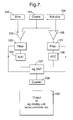
- Fig. 7 is similar to Fig. 1, and the same reference numerals are used to indicate corresponding parts.
- Fig. 7 differs from Fig. 1 in that it requires filters 120, 121 between the differential amplifiers 102, 105 and the analogue to digital converters 103, 106. These filters 120, 121 are controlled by the processor 107 so that their frequency band changes in dependence on the predicted values of the signals from the amplifiers 102, 105. In this way, spurious frequency components can be removed with out compromising the accuracy of the apparatus.
- the derivation of predicted values can most clearly be seen from fig. 5, which shows blocks 231 and 232. Those predicted values are then velocity measurements on which the signals can be filtered.
- This arrangement may further be developed by arranging for the bandwidth of the filter to vary with e.g. measurements of acceleration derived by the processor 107. Whilst a narrow bandwidth is desirable to exclude noise, the range of possible values increases with acceleration. Therefore, it is possible to adjust the bandwidth of the filter so that it is small when the acceleration is small, and increases with increasing acceleration.
- the filters 120, 121 in Fig. 7 can be implemented in several ways, and one possible implementation is illustrated in Fig. 8, with a circuit corresponding to that of Fig. 8 forming the differential amplifier 102 and the filter 120, and the differential amplifier 105 and the filter 121.
- Resistors R7 and R8 are adjustable under the control of the processor 107, but have the same resistance Rf.
- Resistor R5 has resistance Rb, and capacitors C1 and C2 have capacitors Cf and Cb respectively.
- the band width of the filter thus formed is given by 1 / 2 ⁇ Rb Cb and its central frequency is given by 1 / 2 ⁇ Rf Cf.
- the value of resistance Rf is thus made proportional to the velocity prediction derived by the system, and that can be changed by the processor 107 from value to value by varying Rf.
- Control of the resistors R7 and R8 under control of the processor may be achieved by using a resistor with electronically selectable taps with a built in up/down counter. By selecting the resistors to altered via an address line from the processor 107, any by counting up or down, a series of pulses can sent to the electronically selectable taps to either count up or count down depending on the status of the signals. In this way, the resistance of the resistors R7 and R8 can be adjusted. For example, Dallas semiconductor electronically controlled resistor DS1084 may be used having 100 selectable different resistance values. If it is desirable to make the bandwidth of the circuit dependant on the acceleration rate, resistor R5 may also be made variable under control of the processor 107, to vary Rb. In Fig.
- the filters 120, 121 are between the differential amplifiers 102, 105 and the analogue to digital converters 103, 106. It would alternatively be possible for there to be filters in the input lines to the differential amplifiers 102, 105 on the sine, cosine and not sine input 100, 101, 104.
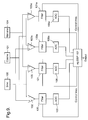
- the velocity prediction is affected by the fact that block 205 acts separately on measurements from each axis system. Therefore, the predictions derived from each axis system may vary slightly. In this case, it is desirable to filter signals corresponding to each axis system separately. The result is that two arrangements similar to Fig. 7 are needed, receiving the same input signals but filtering in dependence on the velocity measurements on the respective two coordinate axis systems. This is illustrated in Fig. 9.
- Fig. 9 the arrangement of Fig. 7 is indicated by the same reference numerals, and a second arrangement of the same construction is illustrated by the same reference numerals but with the letter "a" added.
- the processor then controls the filters 120, 121 in dependence on velocity measurement derived from one axis system, and controls filter 120a 121a independence on a velocity measurement derived from the other axis system.
- the processor 107 then analyses the two results to derive a suitable composite measurement.
- the output of the processor 107 may then be sent to the counter 108 and the output 109 in Fig. 3, although this is not is not illustrated in Fig. 9.
- Fig. 7 and 9 use analogue filtering.
- digital filtering and an arrangement similar to Fig. 9, but making use of digital filtering is shown in Fig. 10.
- Fig. 10 is similar to Fig. 9 and same reference numerals are used to indicate corresponding parts.
- filters 130, 131, 130a and 131a are provided between the analogue to digital converters 103, 106, 103a and 106a and the processor 107.
- the parameters for those digital filters 130, 131, 130a and 131a are provided from the processor 107.
- Digital filtering is known, in itself, and a structure of digital filters which may be used in the present invention is illustrated in e.g. the textbook entitled “Digital Signal Processing Application with Motorola's DSP56002 Processor” by Mohammed El-Sharkawy published by Prentice Hall in 1996, particularly pages 158 to 165. In the design of such a digital filter, the frequency term is made directly related to velocity.
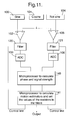
- control of the filter is determined by a prediction derived from analysis using one or more coordinate axis systems, as in Figs. 1 to 6. It is also possible to apply such adjustable filtering to arrangements which do not depend on control using coordinate axis systems. Such an embodiment is illustrated in Fig. 11. Components which correspond to components in Fig. 7 are indicated by the same reference numerals.
- three signals are derived from the encoder or interferometer system.
- the cosine signal is subtracted from the sign and cosine signals to produce two new sine and cosine signals.
- tuneable narrow band pass programmable filter circuits corresponding to those of Fig. 8 are added as shown in Fig. 11.
- the variable resistors R7 and R8 are set to be approximately equal to Rf and C1 so that the centre bandpass frequency is 1 / 2 ⁇ RfCf, where this frequency is the predicted frequency of the input sinusoidal signals. This predicted frequency is directionally proportional to the predicted velocity of the target.
- the bandwidth of the passband of the bandpass filter is given by 1 / 2 ⁇ RbCb where Rb is R5, and Cb is C2.
- the bandwidth of the bandpass filter may also be varied by changing the values of R5 and if necessary C2.
- the output from these two electronically adjustable narrow bandwidth amplifiers are passed to separate clocked analogue to digital converters 103 and 105.
- the clock signal used for controlling this conversion can be derived from a master clock.
- the digital outputs are then passed to for example a microprocessor circuit that computes the phase and signal strength of these two signals.
- the phase is computed by calculating where the sine signal is the output of converter 103 and the cosine signal is the output of converter 106.
- the signal strength is derived from Sine 2 + Cosine 2 . In this arrangement it is preferable that these calculations are completed on or before the next digitally converted signals become available.
- the computed phase is then passed on within the same microprocessor, 140 or to a separate microprocessor, 141 to calculate the current and predicted positions and velocities of the machine.
- the predicted velocity required for controlling the bandwidth and bandpass frequency of the differential amplifier circuits may be different to the predicted velocity required by the machine controllers.
- the time delay between the signals arriving at the analogue to digital converters and obtaining the predicted velocity is three clock cycles, whereas the time delay on when the controller can use the predicted velocities could be considerably longer.
- the advantage of this approach is that the system predicts the bandpass frequency of the subtraction amplifiers, and limit the bandwidth of this circuit to the expected variation in frequency due to the uncertainty in predicting the velocity. This then allows for a reduction in the noise of the system by a factor of approximately three for every decade in reduction in bandwidth. For example, assume that the circuit would require a bandwidth of DC to 10 MHz, using standard electronics, but by adopting the above approach the bandwidth of the circuit could be reduced to 1 KHz, then this would imply a factor of 100 improvement in the signal to noise ratio due to the electronics. For a standard linear HeNe interferometer system with a scale pitch of approximately .03 microns a bandwidth limitation of 1 KHz, implies an uncertainty in the velocity of the system of 0.3 mm s- 1 .
- phase interpolation could be achieved by timing the interval between quadrature transitions and assume that the time required for the next transition was the same as the last transition, and the phase is obtained from the time interval.
- the difference between the traditional methods and the one required with this invention is that the quadrature samples are taken in high rate bursts separated by significantly longer time intervals.
- quad count and phase interpolation need to be stored in a memory buffer so that they become available for the processing unit on demand.
- Additional benefits obtained from this invention include:
- the processing system Since the processing system has a knowledge of the instantaneous velocity it can modify the signals from the processor to compensate for the changes in phase of the quadrature signals as a function of velocity or change in latency of the processing electronics. This is particular useful in closed loop systems as it is possible to build "lag free” control systems and help to reduce servo-control induced resonances and to increase the effective bandwidth.
- Low rate sampling by using undersampling techniques permits time division multiplexing of many quadrature channels. This may be particularly useful in interferometric applications where one could use a single laser to measure many axes of motion and still maintain high signal levels without the need to reduce their bandwidth and or their resolution as in the case of amplitude division to obtain phase information. In this case the laser beam is optically switched between the axes with the rate determined by the low rate sampling counter.
- a further advantage which may be obtained using the present invention is that it is no longer necessary to monitor continuously the signals to ensure appropriate accuracy. This accuracy permits the use of the concept of over sampling.
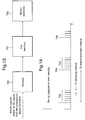
- the process signals are derived from a plurality of samples from the sensors. This is illustrated further in Fig. 13 in which the signals representing motion, which can be digital signals or the outputs of the analogue to digital converters 103, 106 in Fig. 1, are passed via a sampler 700 which samples at a predetermined sampling interval which is relatively short, and the sampled values are stored in a FIFO memory 701 before being passed to a motion estimator 702 which processes the plural values in the memory 701 to derive an appropriate estimate of motion.
- samples 703 are used to derive motion estimate at time 704, samples 705 are used to derive the motion estimation at time 706, etc.
- motion estimator 702 simply to use an average of the sampled values. However, this is not always the best arrangement and other possibilities include applying filtering with weight functions to combat noise, and possibly to derive short term estimates of velocity, acceleration or higher derivatives.
Landscapes
- Physics & Mathematics (AREA)
- General Physics & Mathematics (AREA)
- Engineering & Computer Science (AREA)
- Signal Processing (AREA)
- Length Measuring Devices With Unspecified Measuring Means (AREA)
- Analogue/Digital Conversion (AREA)
- Transmission And Conversion Of Sensor Element Output (AREA)
Applications Claiming Priority (2)
| Application Number | Priority Date | Filing Date | Title |
|---|---|---|---|
| GBGB9927729.5A GB9927729D0 (en) | 1999-11-24 | 1999-11-24 | Motion detection and analysis |
| GB9927729 | 1999-11-24 |
Publications (1)
| Publication Number | Publication Date |
|---|---|
| EP1103790A2 true EP1103790A2 (de) | 2001-05-30 |
Family
ID=10865027
Family Applications (1)
| Application Number | Title | Priority Date | Filing Date |
|---|---|---|---|
| EP00310355A Withdrawn EP1103790A2 (de) | 1999-11-24 | 2000-11-22 | Bewegungsdetektion und Analyse |
Country Status (3)
| Country | Link |
|---|---|
| EP (1) | EP1103790A2 (de) |
| JP (1) | JP2001194184A (de) |
| GB (1) | GB9927729D0 (de) |
Cited By (2)
| Publication number | Priority date | Publication date | Assignee | Title |
|---|---|---|---|---|
| EP1569347A1 (de) * | 2004-02-18 | 2005-08-31 | Fanuc Ltd | Kodierer und Steuervorrichtung für Motor |
| EP1541971A3 (de) * | 2003-12-09 | 2006-04-26 | Fanuc Ltd | Encoder mit Rauschdetektion |
Families Citing this family (2)
| Publication number | Priority date | Publication date | Assignee | Title |
|---|---|---|---|---|
| JP5523664B2 (ja) * | 2007-11-06 | 2014-06-18 | 株式会社ミツトヨ | 干渉計 |
| KR101447445B1 (ko) * | 2013-04-26 | 2014-10-07 | 마루엘에스아이 주식회사 | 아날로그 필터를 포함하는 엔코더 및 밴드폭 조절방법 |
-
1999
- 1999-11-24 GB GBGB9927729.5A patent/GB9927729D0/en not_active Ceased
-
2000
- 2000-11-22 EP EP00310355A patent/EP1103790A2/de not_active Withdrawn
- 2000-11-24 JP JP2000358428A patent/JP2001194184A/ja active Pending
Cited By (6)
| Publication number | Priority date | Publication date | Assignee | Title |
|---|---|---|---|---|
| EP1541971A3 (de) * | 2003-12-09 | 2006-04-26 | Fanuc Ltd | Encoder mit Rauschdetektion |
| CN1323285C (zh) * | 2003-12-09 | 2007-06-27 | 发那科株式会社 | 编码器 |
| US7247839B2 (en) | 2003-12-09 | 2007-07-24 | Fanuc Ltd | Encoder for detecting position or displacement of moving body |
| EP1569347A1 (de) * | 2004-02-18 | 2005-08-31 | Fanuc Ltd | Kodierer und Steuervorrichtung für Motor |
| US7012397B2 (en) | 2004-02-18 | 2006-03-14 | Fanuc Ltd | Encoder and control apparatus for motor |
| CN1992508B (zh) * | 2004-02-18 | 2010-08-11 | 发那科株式会社 | 编码器 |
Also Published As
| Publication number | Publication date |
|---|---|
| JP2001194184A (ja) | 2001-07-19 |
| GB9927729D0 (en) | 2000-01-26 |
Similar Documents
| Publication | Publication Date | Title |
|---|---|---|
| US6556153B1 (en) | System and method for improving encoder resolution | |
| JPH04260983A (ja) | 制御情報の検出方法及び装置 | |
| JP2003254785A (ja) | エンコーダの信号処理装置 | |
| US5065095A (en) | Position detecting apparatus having means for detecting DC components of AC detection signals | |
| US6462683B2 (en) | Circuit configuration and method for setting the switching points of a decision maker | |
| US6934641B2 (en) | Motion detection and analysis | |
| EP1103790A2 (de) | Bewegungsdetektion und Analyse | |
| US20100088053A1 (en) | Phase detection device and position detection device | |
| EP3677873B1 (de) | Sofortkorrekturverfahren für einen codierer und system dafür | |
| JP2011075404A (ja) | デジタルスケールの検出信号補正方法及び検出信号補正装置 | |
| EP0540763B1 (de) | Verfahren und Vorrichtung zur Impulserzeugung | |
| US12176832B2 (en) | Position sensor system and method for detecting an error of a position sensor system | |
| JP2002250639A (ja) | 絶対位置検出エンコーダ | |
| EP1480448A2 (de) | Bewegungsdetektion und Analyse | |
| US7091884B2 (en) | Analog position encoder | |
| JPH08334526A (ja) | 速度検出装置 | |
| EP0200791A1 (de) | Verfahren und vorrichtung zur bestimmung der ortung | |
| JPH03125912A (ja) | 位置検出装置の出力タイミング補間方法 | |
| JPH05256638A (ja) | 誤差補正機能付き位置検出装置 | |
| JP2002243501A (ja) | エンコーダ出力信号の自動調整装置 | |
| JP3439814B2 (ja) | デジタルpll装置 | |
| JPH03296618A (ja) | 内挿のための波形補正方法 | |
| JPH0635502A (ja) | サンプリング系センサのアラーム処理装置 | |
| JP3349575B2 (ja) | 変位速度検出方法および装置 | |
| JP3155180B2 (ja) | パルス周期整形装置、パルス周期検出装置及びパルスノイズ除去装置 |
Legal Events
| Date | Code | Title | Description |
|---|---|---|---|
| PUAI | Public reference made under article 153(3) epc to a published international application that has entered the european phase |
Free format text: ORIGINAL CODE: 0009012 |
|
| AK | Designated contracting states |
Kind code of ref document: A2 Designated state(s): AT BE CH CY DE DK ES FI FR GB GR IE IT LI LU MC NL PT SE TR |
|
| AX | Request for extension of the european patent |
Free format text: AL;LT;LV;MK;RO;SI |
|
| STAA | Information on the status of an ep patent application or granted ep patent |
Free format text: STATUS: THE APPLICATION IS DEEMED TO BE WITHDRAWN |
|
| 18D | Application deemed to be withdrawn |
Effective date: 20060531 |