EP1104049A1 - Connecteur flexible ayant des lignes de transmission intégrées - Google Patents
Connecteur flexible ayant des lignes de transmission intégrées Download PDFInfo
- Publication number
- EP1104049A1 EP1104049A1 EP00123922A EP00123922A EP1104049A1 EP 1104049 A1 EP1104049 A1 EP 1104049A1 EP 00123922 A EP00123922 A EP 00123922A EP 00123922 A EP00123922 A EP 00123922A EP 1104049 A1 EP1104049 A1 EP 1104049A1
- Authority
- EP
- European Patent Office
- Prior art keywords
- flexible
- connector
- reinforcing member
- conductive wires
- insulator
- Prior art date
- Legal status (The legal status is an assumption and is not a legal conclusion. Google has not performed a legal analysis and makes no representation as to the accuracy of the status listed.)
- Granted
Links
Images





Classifications
-
- H—ELECTRICITY
- H05—ELECTRIC TECHNIQUES NOT OTHERWISE PROVIDED FOR
- H05K—PRINTED CIRCUITS; CASINGS OR CONSTRUCTIONAL DETAILS OF ELECTRIC APPARATUS; MANUFACTURE OF ASSEMBLAGES OF ELECTRICAL COMPONENTS
- H05K1/00—Printed circuits
- H05K1/02—Details
- H05K1/0277—Bendability or stretchability details
- H05K1/028—Bending or folding regions of flexible printed circuits
-
- H—ELECTRICITY
- H01—ELECTRIC ELEMENTS
- H01R—ELECTRICALLY-CONDUCTIVE CONNECTIONS; STRUCTURAL ASSOCIATIONS OF A PLURALITY OF MUTUALLY-INSULATED ELECTRICAL CONNECTING ELEMENTS; COUPLING DEVICES; CURRENT COLLECTORS
- H01R35/00—Flexible or turnable line connectors, i.e. the rotation angle being limited
-
- H—ELECTRICITY
- H01—ELECTRIC ELEMENTS
- H01R—ELECTRICALLY-CONDUCTIVE CONNECTIONS; STRUCTURAL ASSOCIATIONS OF A PLURALITY OF MUTUALLY-INSULATED ELECTRICAL CONNECTING ELEMENTS; COUPLING DEVICES; CURRENT COLLECTORS
- H01R12/00—Structural associations of a plurality of mutually-insulated electrical connecting elements, specially adapted for printed circuits, e.g. printed circuit boards [PCB], flat or ribbon cables, or like generally planar structures, e.g. terminal strips, terminal blocks; Coupling devices specially adapted for printed circuits, flat or ribbon cables, or like generally planar structures; Terminals specially adapted for contact with, or insertion into, printed circuits, flat or ribbon cables, or like generally planar structures
- H01R12/70—Coupling devices
- H01R12/77—Coupling devices for flexible printed circuits, flat or ribbon cables or like structures
- H01R12/79—Coupling devices for flexible printed circuits, flat or ribbon cables or like structures connecting to rigid printed circuits or like structures
-
- H—ELECTRICITY
- H01—ELECTRIC ELEMENTS
- H01R—ELECTRICALLY-CONDUCTIVE CONNECTIONS; STRUCTURAL ASSOCIATIONS OF A PLURALITY OF MUTUALLY-INSULATED ELECTRICAL CONNECTING ELEMENTS; COUPLING DEVICES; CURRENT COLLECTORS
- H01R13/00—Details of coupling devices of the kinds covered by groups H01R12/70 or H01R24/00 - H01R33/00
- H01R13/02—Contact members
- H01R13/33—Contact members made of resilient wire
-
- H—ELECTRICITY
- H05—ELECTRIC TECHNIQUES NOT OTHERWISE PROVIDED FOR
- H05K—PRINTED CIRCUITS; CASINGS OR CONSTRUCTIONAL DETAILS OF ELECTRIC APPARATUS; MANUFACTURE OF ASSEMBLAGES OF ELECTRICAL COMPONENTS
- H05K1/00—Printed circuits
- H05K1/02—Details
- H05K1/0213—Electrical arrangements not otherwise provided for
- H05K1/0216—Reduction of cross-talk, noise or electromagnetic interference
- H05K1/0218—Reduction of cross-talk, noise or electromagnetic interference by printed shielding conductors, ground planes or power plane
- H05K1/0224—Patterned shielding planes, ground planes or power planes
-
- H—ELECTRICITY
- H05—ELECTRIC TECHNIQUES NOT OTHERWISE PROVIDED FOR
- H05K—PRINTED CIRCUITS; CASINGS OR CONSTRUCTIONAL DETAILS OF ELECTRIC APPARATUS; MANUFACTURE OF ASSEMBLAGES OF ELECTRICAL COMPONENTS
- H05K1/00—Printed circuits
- H05K1/02—Details
- H05K1/0213—Electrical arrangements not otherwise provided for
- H05K1/0237—High frequency adaptations
-
- H—ELECTRICITY
- H05—ELECTRIC TECHNIQUES NOT OTHERWISE PROVIDED FOR
- H05K—PRINTED CIRCUITS; CASINGS OR CONSTRUCTIONAL DETAILS OF ELECTRIC APPARATUS; MANUFACTURE OF ASSEMBLAGES OF ELECTRICAL COMPONENTS
- H05K2201/00—Indexing scheme relating to printed circuits covered by H05K1/00
- H05K2201/07—Electric details
- H05K2201/0707—Shielding
- H05K2201/0715—Shielding provided by an outer layer of PCB
-
- H—ELECTRICITY
- H05—ELECTRIC TECHNIQUES NOT OTHERWISE PROVIDED FOR
- H05K—PRINTED CIRCUITS; CASINGS OR CONSTRUCTIONAL DETAILS OF ELECTRIC APPARATUS; MANUFACTURE OF ASSEMBLAGES OF ELECTRICAL COMPONENTS
- H05K2201/00—Indexing scheme relating to printed circuits covered by H05K1/00
- H05K2201/09—Shape and layout
- H05K2201/09209—Shape and layout details of conductors
- H05K2201/09654—Shape and layout details of conductors covering at least two types of conductors provided for in H05K2201/09218 - H05K2201/095
- H05K2201/09727—Varying width along a single conductor; Conductors or pads having different widths
-
- H—ELECTRICITY
- H05—ELECTRIC TECHNIQUES NOT OTHERWISE PROVIDED FOR
- H05K—PRINTED CIRCUITS; CASINGS OR CONSTRUCTIONAL DETAILS OF ELECTRIC APPARATUS; MANUFACTURE OF ASSEMBLAGES OF ELECTRICAL COMPONENTS
- H05K3/00—Apparatus or processes for manufacturing printed circuits
- H05K3/10—Apparatus or processes for manufacturing printed circuits in which conductive material is applied to the insulating support in such a manner as to form the desired conductive pattern
- H05K3/20—Apparatus or processes for manufacturing printed circuits in which conductive material is applied to the insulating support in such a manner as to form the desired conductive pattern by affixing prefabricated conductor pattern
- H05K3/202—Apparatus or processes for manufacturing printed circuits in which conductive material is applied to the insulating support in such a manner as to form the desired conductive pattern by affixing prefabricated conductor pattern using self-supporting metal foil pattern
Definitions
- the present invention relates to a flexible connector for connecting two connection objects such as printed circuit boards to each other and, in particular, to a flexible connector having a flexible portion or part between the connection objects.
- JP-Y2 Japanese Utility Model Registration
- JP-U Japanese Unexamined Utility Model Publication
- a flexible printed circuit (hereinafter referred to as "FPC") member 23 is interposed between the printed circuit boards 21 and 22.
- FPC connectors 24 and 25 are mounted on the printed circuit boards 21, 22, respectively.
- One end of the FPC 23 is connected to the FPC connector 24 and the other end of the FPC 23 is connected to the FPC connector 25.
- the FPC connectors 24, 25 are of zero-insertion-force type (hereinafter referred to as "ZIF type"), members such as sliders for the fitting/removing operation of the connectors are required and the operation of such members such as sliders is complex.
- ZIF type zero-insertion-force type
- the FPC connectors 24, 25 are of Non-ZIF type, such members such as sliders and its operation are not required, but the fitting portions of the FPC 23 with the FPC connectors 24, 25 are easy to be broken during the fitting/removing operation.
- the FPC 23 should be manufactured as a separate part, thus increasing the cost.
- the FPC 23 and the FPC connectors 24, 25 are normally manufactured by different manufacturers, it is difficult to provide assurance for the electrical performance (for example, impedance matching).
- a FPC 23 and two FPC relay connectors 26, 27 are interposed between the printed circuits 21 and 22.
- plug or receptacle connectors 28, 29 are mounted on the printed circuit boards 21, 22, respectively.
- One end of the FPC 23 is connected to the plug connectors or receptacle connector 28 via the FPC relay connector 26 and the other end of the FPC 23 is connected to the plug or receptacle connector 29 via the FPC relay connector 27.
- the FPC 23 should be manufactured as a separate part, thus further increasing the cost. Moreover, since the FPC 23, the FPC relay connectors 26, 27, and the plug or receptacle connectors 28, 29 are normally manufactured by different manufacturers, it is difficult to provide assurance for the electrical performance.
- a flexible connector to which the present invention is applicable has a fitting portion for being connected with a counterpart connector.
- the flexible connector comprises a plurality of flexible conductive wires arranged on a plane in parallel to each other and extending in a predetermined direction to have end portions, a flexible reinforcing member placed at one side of the plane to reinforce the flexible conductive wires, an insulator holding the flexible conductive wires to make the fitting portion in cooperation with the end portions of the flexible conductive wires, and coupling means connected to the insulator and the flexible reinforcing member for mechanically coupling the insulator to the flexible reinforcing member.
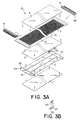
- the flexible connector is designated by numeral "1" and includes a flexible high-speed transmission line 2 and insulators 8 attached to the both ends of the length of the high-speed transmission line 2 by integral molding or insertion.
- the high-speed transmission line 2 includes a conductor 3 manufactured by pressing or etching, an upper insulating sheet 4 attached to the front surface of the conductor 3; a middle insulating sheet 5 attached to the rear surface of the conductor 3, a thin metallic plate 6 attached as a flexible reinforcing member to the rear surface of the second insulating sheet 5, and a lower insulating sheet 7 attached to the rear surface of the metallic plate 6.
- the metallic plate 6 is formed with contact portions 61 at both ends in a predetermined or longitudinal direction thereof.
- Each of the contact portions 61 includes engaging portions 62 formed by bending both ends in a width or cross direction thereof.
- Each of the engaging portions 62 has a pair of L-like holes 63 formed therein.
- the middle insulating sheet 5 will be referred to as a first insulating sheet.
- the upper insulating sheet 4 will be referred to as a second insulating sheet.
- the lower insulating sheet 7 will be referred to as a third insulating sheet.
- Each of the insulators 8 is formed with a pair of claws 83 as a first engaging portion on both ends of the width thereof.
- the L-like holes 63 of the engaging portions 62 are engaged with the claws 83 of the insulators 8 as shown in Fig. 3B.
- the engaging portions 62 serve as a second engaging portion.
- a combination of the claws 83 and the engaging portions 62 is referred to as a coupling arrangement.
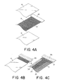
- the conductor 3 is previously formed with a plurality of flexible conductive wires 31 equal in width spaced at equal intervals. Then, the first insulating sheet 4 and the second insulating sheet 5 are attached to the front surface and the rear surface of the conductor 3, respectively, as shown in Fig. 4B. It should be noted that carriers 35 are connected integrally to both ends of the conductor 3 in the longitudinal direction. For the current capacity for a power source, the impedance, and the like, one of the flexible conductive wires 31 may have different width selected according to the pin assignment.
- the conductor 3 may be previously formed with a first wire group comprising a plurality of flexible conductive wires 32 of small width, a second wire group comprising a plurality of flexible conductive wires 33 of middle width, and a third wire group comprising a plurality of flexible conductive wires 34 of large width.
- the flexible conductive wires are grouped into a plurality of wire groups between which the flexible conductive wires have different widths.
- each insulator 8 is attached to extend along the pattern 31 having the wires equal in width and the first insulating sheet 4 by integral molding or insertion.
- the attached state is shown in Fig. 5B.
- each elongated hole 64 is previously formed in the metallic plate 6 to extend along the length of the metallic plate 6.
- the width of each elongated hole 64 is slightly larger than the width of each slit 41 formed in the upper, the middle, and the lower insulating sheets 4, 5, and 7 as described later.
- the front surface of the metallic plate 6 is attached to the rear surface of the middle insulating sheet 5 and the pairs of L-like holes 63 of the metallic plate 6 are engaged with the pairs of pawls 83 of the respective insulators 8.
- the lower insulating sheet 7 is attached to the rear surface of the metallic plate 6.
- the carriers 35 and parts of the pattern 31 near the carriers 35 of the conductor 3 are cut and removed.
- two slits 41 are cut or formed in the lamination of the upper insulating sheet 4, the conductor 3, the middle insulating sheet 5, the metallic plate 6, and the lower insulating sheet 7 by a cutter.
- the edge of the cutter is placed to a portion between one wire of the pattern 31 and the adjacent one of the pattern 31 and in the each elongated hole 64 of the metallic plate 6.
- This state of the connector 1 is shown in Fig. 6B.
- the slits 41 are formed in the upper, the middle, and the lower insulating sheets 4, 5, and 7 and improve the flexibility of the high-speed transmission line 2.
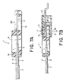
- the conductor 3, the upper insulating sheet 4, and the middle insulating sheet 5 are held and secured to a body 81 of the each insulator 8. Further, the end of the pattern 31 of the conductor 3 is held and secured to an fitting portion 82 of the each insulator 8.
- Each engaging portion 62 of the metallic plate 6 is engaged with the each insulator 8 so that the metallic plate 6 and the insulators 8 are integrated.
- the metallic plate 6 is provided at its ends with the contact portions 61 (see Fig. 3A) which serve as ground parts and come in contact with a plurality of ground contacts of a counterpart connector.
- the relative connector 11 includes an insulator 12, a plurality of signal contacts 13 and ground contacts 14 aligned on the insulator 12 for press engaging, and a shell 15 covering the insulator 12 and held by the insulator 12.
- the pattern 31 at the end of the contact 3 of the flexible connector 1 is in contact with the respective signal contacts 13 of the relative connector 11 and the contact portion 61 of the metallic plate 6 is in contact with the respective ground contacts 14 of the relative connector 11.
- Fig. 8A shows a case that the first printed circuit board 21 and the second printed circuit board 22 are at the same level.
- Fig. 8B shows a case that the both circuit boards 21 and 22 are at different levels and are disposed such that the respective rear surfaces of the circuit boards 21 and 22 face to each other.
- Fig. 8C shows a case that the both circuit boards 21 and 22 are at different levels and are disposed such that the rear surface of the first printed circuit board 21 faces to the front surface of the second printed circuit board 22.
- the aforementioned flexible connector 1 exhibits the following effects:
Landscapes
- Engineering & Computer Science (AREA)
- Microelectronics & Electronic Packaging (AREA)
- Coupling Device And Connection With Printed Circuit (AREA)
- Details Of Connecting Devices For Male And Female Coupling (AREA)
Applications Claiming Priority (2)
| Application Number | Priority Date | Filing Date | Title |
|---|---|---|---|
| JP33484799 | 1999-11-25 | ||
| JP33484799A JP3505640B2 (ja) | 1999-11-25 | 1999-11-25 | フレキシブルな伝送線路一体型コネクタ |
Publications (2)
| Publication Number | Publication Date |
|---|---|
| EP1104049A1 true EP1104049A1 (fr) | 2001-05-30 |
| EP1104049B1 EP1104049B1 (fr) | 2003-04-23 |
Family
ID=18281894
Family Applications (1)
| Application Number | Title | Priority Date | Filing Date |
|---|---|---|---|
| EP00123922A Expired - Lifetime EP1104049B1 (fr) | 1999-11-25 | 2000-11-03 | Connecteur flexible ayant des lignes de transmission intégrées |
Country Status (6)
| Country | Link |
|---|---|
| US (1) | US6743045B1 (fr) |
| EP (1) | EP1104049B1 (fr) |
| JP (1) | JP3505640B2 (fr) |
| KR (1) | KR100431765B1 (fr) |
| DE (1) | DE60002281T2 (fr) |
| TW (1) | TW533629B (fr) |
Cited By (5)
| Publication number | Priority date | Publication date | Assignee | Title |
|---|---|---|---|---|
| EP1168511A3 (fr) * | 2000-06-22 | 2003-01-08 | Cray Inc. | Connecteur électrique de circuit imprimé avec support |
| EP1549117A1 (fr) * | 2003-12-26 | 2005-06-29 | Olympus Corporation | Endoscope ultrasonique avec connecteur de câble pour les signaux ultrasonore |
| EP1501340A3 (fr) * | 2003-07-24 | 2005-11-09 | NEC Corporation | Substrat flexible et dispositif électronique |
| GB2466534A (en) * | 2008-12-26 | 2010-06-30 | Askey Computer Corp | Framework of a wireless network access device |
| EP2940805A4 (fr) * | 2012-12-26 | 2016-07-27 | Sony Corp | Connecteur, appareil de réception de données, appareil de transmission de données, et système de transmission/réception de données |
Families Citing this family (17)
| Publication number | Priority date | Publication date | Assignee | Title |
|---|---|---|---|---|
| JP4337478B2 (ja) * | 2003-09-02 | 2009-09-30 | 日本電気株式会社 | 外部接続端子保持構造 |
| US20060035487A1 (en) * | 2004-08-12 | 2006-02-16 | Acer Inc. | Flexible hybrid cable |
| US6981891B1 (en) * | 2004-10-19 | 2006-01-03 | Alex Huang | Flexible flat cable connector |
| DE202005018318U1 (de) * | 2005-10-28 | 2007-03-15 | Weidmüller Interface GmbH & Co. KG | Steckverbindung für Flachkabel und Kontaktelement für eine derartige Steckverbindung |
| US20070221402A1 (en) * | 2006-03-22 | 2007-09-27 | Alex Huang | Soft wire bank joint device |
| JP5247509B2 (ja) * | 2009-02-10 | 2013-07-24 | キヤノン株式会社 | 電子機器 |
| TWM405673U (en) * | 2010-12-03 | 2011-06-11 | Adv Flexible Circuits Co Ltd | Flexible cable with electromagnetic shielding connector structure |
| EP2661791B1 (fr) * | 2011-01-05 | 2015-03-04 | Thomson Licensing | Appareil électronique comprenant des circuits imprimés interconnectés par un circuit flexible à impédance controllée |
| CN202797404U (zh) * | 2012-07-12 | 2013-03-13 | 富士康(昆山)电脑接插件有限公司 | 柔性扁平线缆组件 |
| MX359326B (es) * | 2013-05-14 | 2018-09-25 | Adc Telecommunications Inc | Cable híbrido de alimentación/fibra. |
| CN111034370A (zh) * | 2017-08-14 | 2020-04-17 | 住友电工印刷电路株式会社 | 柔性印刷电路板 |
| US10697567B2 (en) | 2017-09-25 | 2020-06-30 | Baker Hughes, A Ge Company, Llc | Flexible device and method |
| US10903594B2 (en) * | 2018-10-01 | 2021-01-26 | Te Connectivity Corporation | Board-to-board connector assembly for add-in cards |
| US11398694B2 (en) * | 2020-09-29 | 2022-07-26 | TE Connectivity Services Gmbh | Flex jumper assembly for a plug connector assembly |
| CN116746286A (zh) * | 2021-11-25 | 2023-09-12 | 微软技术许可有限责任公司 | 电缆连接器 |
| KR102667271B1 (ko) * | 2022-01-07 | 2024-05-20 | 이준호 | 밴드타입 커넥터 |
| CN118099779A (zh) * | 2022-11-28 | 2024-05-28 | 北京字跳网络技术有限公司 | 接地装置及电子设备 |
Citations (2)
| Publication number | Priority date | Publication date | Assignee | Title |
|---|---|---|---|---|
| US4812135A (en) * | 1984-07-26 | 1989-03-14 | The General Electric Company, P.L.C. | Flexible electrical connectors |
| EP0476355A1 (fr) * | 1990-09-05 | 1992-03-25 | THOMAS & BETTS CORPORATION | Dispositif de proctection de transport et d'insertion pour câbles multiconducteurs |
Family Cites Families (10)
| Publication number | Priority date | Publication date | Assignee | Title |
|---|---|---|---|---|
| US476355A (en) * | 1892-06-07 | Sulky plow | ||
| US3728661A (en) * | 1970-03-12 | 1973-04-17 | Honeywell Inf Systems | Modular cabling system |
| FR2283528A1 (fr) * | 1974-08-30 | 1976-03-26 | Reinshagen Kabelwerk Gmbh | Connexion omnibus de cables et procede pour sa fabrication |
| FR2647971B1 (fr) * | 1989-06-01 | 1991-09-20 | Itt Composants Instr | Ensemble de connexion pour cartes a circuits imprimes |
| JPH0729609B2 (ja) | 1991-09-10 | 1995-04-05 | 大和産業株式会社 | 手押し車の握り部 |
| JPH05298939A (ja) * | 1992-04-16 | 1993-11-12 | Honda Tsushin Kogyo Kk | フラットケーブル及びその製造方法 |
| JP3196018B2 (ja) * | 1997-03-31 | 2001-08-06 | 日本航空電子工業株式会社 | シールド機構付き中継コネクタ |
| JPH11232932A (ja) * | 1997-12-12 | 1999-08-27 | Whitaker Corp:The | フラットケーブル組立体及びそれに使用されるフラットケーブル |
| US6062900A (en) * | 1998-11-30 | 2000-05-16 | Hon Hai Precision Ind. Co., Ltd. | ZIF FFC connector having a strain relief |
| US6302705B1 (en) * | 2000-06-22 | 2001-10-16 | Cray Inc. | Electrical circuit connector with support |
-
1999
- 1999-11-25 JP JP33484799A patent/JP3505640B2/ja not_active Expired - Fee Related
-
2000
- 2000-10-31 TW TW089122884A patent/TW533629B/zh not_active IP Right Cessation
- 2000-11-02 US US09/705,247 patent/US6743045B1/en not_active Expired - Lifetime
- 2000-11-03 DE DE60002281T patent/DE60002281T2/de not_active Expired - Lifetime
- 2000-11-03 EP EP00123922A patent/EP1104049B1/fr not_active Expired - Lifetime
- 2000-11-25 KR KR10-2000-0070638A patent/KR100431765B1/ko not_active Expired - Lifetime
Patent Citations (2)
| Publication number | Priority date | Publication date | Assignee | Title |
|---|---|---|---|---|
| US4812135A (en) * | 1984-07-26 | 1989-03-14 | The General Electric Company, P.L.C. | Flexible electrical connectors |
| EP0476355A1 (fr) * | 1990-09-05 | 1992-03-25 | THOMAS & BETTS CORPORATION | Dispositif de proctection de transport et d'insertion pour câbles multiconducteurs |
Non-Patent Citations (1)
| Title |
|---|
| N.KATO: "one-touch connectors assure improved operability with flexible printed circuits", JOURNAL OF ELECTRONIC ENGINEERING, vol. 31, no. 327, March 1994 (1994-03-01), tokyo,jp, pages 94 - 97, XP000429336 * |
Cited By (8)
| Publication number | Priority date | Publication date | Assignee | Title |
|---|---|---|---|---|
| EP1168511A3 (fr) * | 2000-06-22 | 2003-01-08 | Cray Inc. | Connecteur électrique de circuit imprimé avec support |
| EP1501340A3 (fr) * | 2003-07-24 | 2005-11-09 | NEC Corporation | Substrat flexible et dispositif électronique |
| CN100433948C (zh) * | 2003-07-24 | 2008-11-12 | 日本电气株式会社 | 柔性衬底和电子设备 |
| US7531752B2 (en) | 2003-07-24 | 2009-05-12 | Nec Corporation | Flexible substrate and electronic device |
| EP1549117A1 (fr) * | 2003-12-26 | 2005-06-29 | Olympus Corporation | Endoscope ultrasonique avec connecteur de câble pour les signaux ultrasonore |
| GB2466534A (en) * | 2008-12-26 | 2010-06-30 | Askey Computer Corp | Framework of a wireless network access device |
| GB2466534B (en) * | 2008-12-26 | 2012-08-15 | Askey Computer Corp | Framework of wireless network access device |
| EP2940805A4 (fr) * | 2012-12-26 | 2016-07-27 | Sony Corp | Connecteur, appareil de réception de données, appareil de transmission de données, et système de transmission/réception de données |
Also Published As
| Publication number | Publication date |
|---|---|
| DE60002281D1 (de) | 2003-05-28 |
| KR100431765B1 (ko) | 2004-05-17 |
| TW533629B (en) | 2003-05-21 |
| KR20010051954A (ko) | 2001-06-25 |
| JP3505640B2 (ja) | 2004-03-08 |
| US6743045B1 (en) | 2004-06-01 |
| JP2001155806A (ja) | 2001-06-08 |
| DE60002281T2 (de) | 2003-12-04 |
| EP1104049B1 (fr) | 2003-04-23 |
Similar Documents
| Publication | Publication Date | Title |
|---|---|---|
| US6743045B1 (en) | Flexible transmission link having integral connectors | |
| US6250935B1 (en) | Electrical connector | |
| US7189105B2 (en) | Connector suitable for connection of a thin sheet member | |
| US20060128197A1 (en) | Board mounted power connector | |
| US7115005B2 (en) | Electrical connector having resilient contacts | |
| JPH0613134A (ja) | 接地バスを有するコネクタ | |
| JP2005322470A (ja) | コネクタ | |
| EP1109258A2 (fr) | Connecteur pour câble plat | |
| US7297029B2 (en) | Communication control IC-incorporating connector and wiring harness with communication control IC-incorporating connector | |
| JP2596420Y2 (ja) | アース用コネクタ | |
| GB2130448A (en) | Improvements in electrical contact members and electrical connector assemblies | |
| KR20060050339A (ko) | 커넥터 | |
| JP3512088B2 (ja) | フラットケーブルの接続構造 | |
| EP1469558B1 (fr) | Connecteur adapté pour la transmission de signaux symétriques et substrat de montage | |
| JP2549583Y2 (ja) | フレキシブルプリント配線板 | |
| CN211789680U (zh) | 插座连接器 | |
| US7309254B2 (en) | Connector which can be increased in holding strength with respect to a substrate | |
| JP5218786B2 (ja) | コネクタ装置 | |
| JP4070988B2 (ja) | 平型柔軟ケーブル用コネクタ | |
| JP2011003393A (ja) | コネクタ装置 | |
| US6116948A (en) | Electrical connector for terminating discrete electrical wires | |
| GB2139122A (en) | A method of forming electrically conductive pins | |
| JP2893434B2 (ja) | コネクタ | |
| US6979237B2 (en) | Electrical connector having receptacle contacts | |
| EP0848584A1 (fr) | Dispositif tridimensionnel de connexion électrique |
Legal Events
| Date | Code | Title | Description |
|---|---|---|---|
| PUAI | Public reference made under article 153(3) epc to a published international application that has entered the european phase |
Free format text: ORIGINAL CODE: 0009012 |
|
| AK | Designated contracting states |
Kind code of ref document: A1 Designated state(s): DE FI FR GB NL |
|
| AX | Request for extension of the european patent |
Free format text: AL;LT;LV;MK;RO;SI |
|
| 17P | Request for examination filed |
Effective date: 20011116 |
|
| AKX | Designation fees paid |
Free format text: DE FI FR GB NL |
|
| 17Q | First examination report despatched |
Effective date: 20020124 |
|
| GRAG | Despatch of communication of intention to grant |
Free format text: ORIGINAL CODE: EPIDOS AGRA |
|
| GRAG | Despatch of communication of intention to grant |
Free format text: ORIGINAL CODE: EPIDOS AGRA |
|
| GRAG | Despatch of communication of intention to grant |
Free format text: ORIGINAL CODE: EPIDOS AGRA |
|
| GRAH | Despatch of communication of intention to grant a patent |
Free format text: ORIGINAL CODE: EPIDOS IGRA |
|
| GRAH | Despatch of communication of intention to grant a patent |
Free format text: ORIGINAL CODE: EPIDOS IGRA |
|
| GRAA | (expected) grant |
Free format text: ORIGINAL CODE: 0009210 |
|
| AK | Designated contracting states |
Designated state(s): DE FI FR GB NL |
|
| REG | Reference to a national code |
Ref country code: GB Ref legal event code: FG4D |
|
| REF | Corresponds to: |
Ref document number: 60002281 Country of ref document: DE Date of ref document: 20030528 Kind code of ref document: P |
|
| ET | Fr: translation filed | ||
| PLBE | No opposition filed within time limit |
Free format text: ORIGINAL CODE: 0009261 |
|
| STAA | Information on the status of an ep patent application or granted ep patent |
Free format text: STATUS: NO OPPOSITION FILED WITHIN TIME LIMIT |
|
| 26N | No opposition filed |
Effective date: 20040126 |
|
| PGFP | Annual fee paid to national office [announced via postgrant information from national office to epo] |
Ref country code: FI Payment date: 20071109 Year of fee payment: 8 |
|
| PG25 | Lapsed in a contracting state [announced via postgrant information from national office to epo] |
Ref country code: FI Free format text: LAPSE BECAUSE OF NON-PAYMENT OF DUE FEES Effective date: 20081103 |
|
| REG | Reference to a national code |
Ref country code: FR Ref legal event code: PLFP Year of fee payment: 16 |
|
| REG | Reference to a national code |
Ref country code: FR Ref legal event code: PLFP Year of fee payment: 17 |
|
| REG | Reference to a national code |
Ref country code: FR Ref legal event code: PLFP Year of fee payment: 18 |
|
| REG | Reference to a national code |
Ref country code: FR Ref legal event code: PLFP Year of fee payment: 19 |
|
| PGFP | Annual fee paid to national office [announced via postgrant information from national office to epo] |
Ref country code: DE Payment date: 20191022 Year of fee payment: 20 Ref country code: NL Payment date: 20191014 Year of fee payment: 20 |
|
| PGFP | Annual fee paid to national office [announced via postgrant information from national office to epo] |
Ref country code: FR Payment date: 20191015 Year of fee payment: 20 |
|
| PGFP | Annual fee paid to national office [announced via postgrant information from national office to epo] |
Ref country code: GB Payment date: 20191031 Year of fee payment: 20 |
|
| REG | Reference to a national code |
Ref country code: DE Ref legal event code: R071 Ref document number: 60002281 Country of ref document: DE |
|
| REG | Reference to a national code |
Ref country code: NL Ref legal event code: MK Effective date: 20201102 |
|
| REG | Reference to a national code |
Ref country code: GB Ref legal event code: PE20 Expiry date: 20201102 |
|
| PG25 | Lapsed in a contracting state [announced via postgrant information from national office to epo] |
Ref country code: GB Free format text: LAPSE BECAUSE OF EXPIRATION OF PROTECTION Effective date: 20201102 |