EP1104065A1 - Kabelverriegelungsvorrichtung für die Einbaudose eines elektrischen Gerätes - Google Patents
Kabelverriegelungsvorrichtung für die Einbaudose eines elektrischen Gerätes Download PDFInfo
- Publication number
- EP1104065A1 EP1104065A1 EP00500240A EP00500240A EP1104065A1 EP 1104065 A1 EP1104065 A1 EP 1104065A1 EP 00500240 A EP00500240 A EP 00500240A EP 00500240 A EP00500240 A EP 00500240A EP 1104065 A1 EP1104065 A1 EP 1104065A1
- Authority
- EP
- European Patent Office
- Prior art keywords
- assembly box
- away portion
- cut
- electrical conductor
- window
- Prior art date
- Legal status (The legal status is an assumption and is not a legal conclusion. Google has not performed a legal analysis and makes no representation as to the accuracy of the status listed.)
- Withdrawn
Links
Images
Classifications
-
- H—ELECTRICITY
- H02—GENERATION; CONVERSION OR DISTRIBUTION OF ELECTRIC POWER
- H02G—INSTALLATION OF ELECTRIC CABLES OR LINES, OR OF COMBINED OPTICAL AND ELECTRIC CABLES OR LINES
- H02G3/00—Installations of electric cables or lines or protective tubing therefor in or on buildings, equivalent structures or vehicles
- H02G3/02—Details
- H02G3/08—Distribution boxes; Connection or junction boxes
- H02G3/081—Bases, casings or covers
- H02G3/083—Inlets
- H02G3/085—Inlets including knock-out or tear-out sections
Definitions
- This invention relates to a cable trapping device for an electrical apparatus assembly box.
- the device consists of an arrangement of the type which is located in, or in the proximity of, the connection windows of an electrical apparatus assembly box, particularly where the apparatus is to be mounted in openable raceways for electrical conductors, and which allows an insulated electrical conductor to be slid in lengthwise in one direction and prevents removal from the apparatus by sliding in the opposite direction, with a view to allowing the apparatus to be connected to the electrical conductors and securing such connection against pulling forces exerted on said conductors away from said assembly box.
- the cable trapping device for an electrical apparatus assembly box of the invention has been devised. Accordingly, the windows for the passage of the electrical connecting conductors contemplated in the electrical apparatus assembly box are provided with a fixed curved cut-away portion, the shape of which conforms to the diameters of a range of insulated conductors appropriate for the power of the apparatus, and which is disposed opposite to a similar moving cut-away portion provided in the free end of resilient tab. A passage is formed between said fixed and moving cut-away portions.
- the lesser dimension of the passage in the longitudinal direction of the tab is smaller than the diameter of the electrical conductors to be connected, it allows the electrical conductors to pass in the direction of entry into the electrical apparatus assembly box for connection, by flexing of the tab inwardly of the box. On the other hand, it prevents disconnection of the electrical conductors by retaining them against pulling forces exerted in a longitudinal direction away from the box, by wedging of the moving cut-away portion of the resilient tab against the insulation of the electrical conductor.
- a preferred feature of the invention is that both the resilient tabs and the fixed cut-away portions are formed integral with the electrical apparatus assembly box without excluding, however, that one or the other or both of them may be inserts.
- a further feature of the invention is that the fixed cut-away portion is situated on the edge of the windows closest to the bottom wall of the electrical apparatus assembly box.
- the width of the resilient tabs and of the fixed cut-away portion is smaller than the width of the windows in which they are disposed.
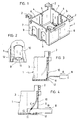
- Figure 1 is a perspective view of assembly box for electrical apparatus provided with the cable trapping devices of the invention.
- Figure 2 is a front elevation view of a part of a wall of the box of the previous figure corresponding to the arrangement of a cable trapping device according to the invention in a connection window thereof.
- Figure 3 is a cross section view of the box of Figure 1, along a mean longitudinal plane passing through one of the connection window thereof provided with the device of the invention, showing the position of the cable trapping device and of a cable or electrical conductor before penetration of the latter in the box for connection thereof to the electrical apparatus.
- Figure 4 is a similar view to the previous figure, in which the electrical conductor has been inserted in the box, has been connected to the electrical apparatus and has been retained in the box by wedging of the cable trapping device of the invention.
- Figure 1 shows a box 1 for the assembly of electrical apparatus such a plug sockets, circuit breakers, switches, fuses, differential switches, etc., which is provided with means for being supported in a raceway, not shown, which in the present example have the form of arms 2 which may be inserted in slots provided in the raceway, with means for installation of the electrical apparatus 3, formed here by a frame, not shown either, which is attached to the box with the apparatus by means of screws threaded into blind holes 4 of the columns 5 provided in the longitudinal walls 6, parallel to the walls of the raceway in which the box is installed, and in the transverse walls 7 which, as the name thereof indicates, are transverse to the walls of the raceway and, finally, with access means allowing for insertion of an electrical conductor 8, formed in this case by connection windows 9 which are openable, unlike the usual situation of other boxes, in which such access means are formed by weakened areas of the appropriate walls of the assembly box and which may be broken to a greater or lesser extent, depending on the gauge of the pertinent electrical cable.
- electrical apparatus such a
- connection windows is obtained by the arrangement therein of resilient tabs 10 which are provided with a moving cut-away portion 11 and are disposed coplanar with and opposite to a fixed cut-away portion 12.
- the resilient tabs 10 and the facing fixed cut-away portions 12 are formed integral with the assembly box 1 itself. Nevertheless, the resilient tabs 10 and, even, the fixed cut-away portions 12 may consist of inserts attached to the box by mechanical arrangements such as plugging-in, rivetting, etc., or even by adhesive arrangements such as welding, gluing, etc.
- the ensemble of resilient tab 10 and fixed cut-away portion 12 is comprised in the opening of the connection window 9, as may be seen in the figures, with the width of the resilient tabs 10 being preferably less than the width of the connection window 9, at the same time as the fixed cut-away portion 12 forms one side of the connection window 9 in opposition to the root of the resilient tab 10 in the assembly box 1 for electrical apparatus 3.
Landscapes
- Engineering & Computer Science (AREA)
- Architecture (AREA)
- Civil Engineering (AREA)
- Structural Engineering (AREA)
- Connection Or Junction Boxes (AREA)
- Insertion, Bundling And Securing Of Wires For Electric Apparatuses (AREA)
Applications Claiming Priority (2)
| Application Number | Priority Date | Filing Date | Title |
|---|---|---|---|
| ES9902972U ES1044705Y (es) | 1999-11-24 | 1999-11-24 | Dispositivo cazacables para cajas de montaje de mecanismos electricos. |
| ES9902972U | 1999-11-24 |
Publications (1)
| Publication Number | Publication Date |
|---|---|
| EP1104065A1 true EP1104065A1 (de) | 2001-05-30 |
Family
ID=8311213
Family Applications (1)
| Application Number | Title | Priority Date | Filing Date |
|---|---|---|---|
| EP00500240A Withdrawn EP1104065A1 (de) | 1999-11-24 | 2000-11-20 | Kabelverriegelungsvorrichtung für die Einbaudose eines elektrischen Gerätes |
Country Status (2)
| Country | Link |
|---|---|
| EP (1) | EP1104065A1 (de) |
| ES (1) | ES1044705Y (de) |
Cited By (4)
| Publication number | Priority date | Publication date | Assignee | Title |
|---|---|---|---|---|
| US8669471B2 (en) | 2010-09-14 | 2014-03-11 | Southwire Company | Electrical accessories and associated methods of use and manufacture |
| US8789256B2 (en) | 2010-09-14 | 2014-07-29 | Southwire Company, Llc | Folded electrical junction boxes and associated methods of use and manufacture |
| US9819167B2 (en) | 2009-09-04 | 2017-11-14 | Cantex, Inc. | Electrical accessories and associated methods of use and manufacture |
| US11296489B2 (en) | 2018-08-01 | 2022-04-05 | Erico International Corporation | Support system for electrical boxes |
Citations (6)
| Publication number | Priority date | Publication date | Assignee | Title |
|---|---|---|---|---|
| US4304958A (en) * | 1980-03-03 | 1981-12-08 | Neff Steve W | Electrical outlet box |
| CH628759A5 (en) * | 1979-12-20 | 1982-03-15 | Hans Felder | Combined electrical insulation socket |
| US4335271A (en) * | 1979-02-20 | 1982-06-15 | Highland Mfg. Company Ltd. | Electrical box |
| US4350839A (en) * | 1980-07-18 | 1982-09-21 | Square D Company | Cable lock for electrical outlet box |
| US4874905A (en) * | 1988-10-31 | 1989-10-17 | Hubbell Incorporated | Cable clamps for electrical box |
| US4970350A (en) * | 1988-04-29 | 1990-11-13 | Harrington Robert W | Cable connector |
-
1999
- 1999-11-24 ES ES9902972U patent/ES1044705Y/es not_active Expired - Fee Related
-
2000
- 2000-11-20 EP EP00500240A patent/EP1104065A1/de not_active Withdrawn
Patent Citations (7)
| Publication number | Priority date | Publication date | Assignee | Title |
|---|---|---|---|---|
| US4335271A (en) * | 1979-02-20 | 1982-06-15 | Highland Mfg. Company Ltd. | Electrical box |
| US4335271B1 (de) * | 1979-02-20 | 1990-04-10 | Hubbell Inc | |
| CH628759A5 (en) * | 1979-12-20 | 1982-03-15 | Hans Felder | Combined electrical insulation socket |
| US4304958A (en) * | 1980-03-03 | 1981-12-08 | Neff Steve W | Electrical outlet box |
| US4350839A (en) * | 1980-07-18 | 1982-09-21 | Square D Company | Cable lock for electrical outlet box |
| US4970350A (en) * | 1988-04-29 | 1990-11-13 | Harrington Robert W | Cable connector |
| US4874905A (en) * | 1988-10-31 | 1989-10-17 | Hubbell Incorporated | Cable clamps for electrical box |
Cited By (5)
| Publication number | Priority date | Publication date | Assignee | Title |
|---|---|---|---|---|
| US9819167B2 (en) | 2009-09-04 | 2017-11-14 | Cantex, Inc. | Electrical accessories and associated methods of use and manufacture |
| US8669471B2 (en) | 2010-09-14 | 2014-03-11 | Southwire Company | Electrical accessories and associated methods of use and manufacture |
| US8789256B2 (en) | 2010-09-14 | 2014-07-29 | Southwire Company, Llc | Folded electrical junction boxes and associated methods of use and manufacture |
| US11296489B2 (en) | 2018-08-01 | 2022-04-05 | Erico International Corporation | Support system for electrical boxes |
| US12294208B2 (en) | 2018-08-01 | 2025-05-06 | Erico International Corporation | Support system for electrical boxes |
Also Published As
| Publication number | Publication date |
|---|---|
| ES1044705U (es) | 2000-06-01 |
| ES1044705Y (es) | 2000-10-16 |
Similar Documents
| Publication | Publication Date | Title |
|---|---|---|
| US4021604A (en) | Flexible conduit connector | |
| US2973212A (en) | Electric connectors for outlet boxes | |
| FI97574C (fi) | Kaapeliliitos | |
| US20080020612A1 (en) | Clamping Apparatus for Connecting Ground Wire to Grounding Member | |
| US5013872A (en) | Cable clamp | |
| JPH0629050A (ja) | 接続クリップ | |
| US6177633B1 (en) | Cable connector | |
| US4223971A (en) | Electrical wiring assembly and method | |
| NO157520B (no) | Anordning for elektrisk forbindelse av ikke isolerte ledninger med strekkavlastere for hver ledning. | |
| US4845312A (en) | Electrical outlet box and outlet therefor | |
| US4366344A (en) | Connector for a helically grooved electrical conductor | |
| EP1104065A1 (de) | Kabelverriegelungsvorrichtung für die Einbaudose eines elektrischen Gerätes | |
| WO1999031762A1 (en) | Insulation piercing wedge connector with piercing support wedge | |
| US4685756A (en) | Drop-wire closure having a high axial strength | |
| EP0065357B1 (de) | Steckverbinder mit einer schwachen Einführkraft | |
| US6572399B2 (en) | Electrical connector | |
| US6846206B2 (en) | Electrical plug connector | |
| US20060000631A1 (en) | Connector for flexible electrical conduit | |
| US4981444A (en) | Strain relief assembly | |
| KR100256632B1 (ko) | 성형 절연 케이스 전기 개폐장치로의 도체 접속단자 | |
| US20070082539A1 (en) | Insulation displacement connection for securing an insulated conductor | |
| GB2298320A (en) | A terminal | |
| GB2057792A (en) | Non-rewirable electric plug | |
| FI96726B (fi) | Kiskoliitin maakaapelin liittämiseksi jonovarokkeeseen | |
| EP0991138A3 (de) | Elektrischer Verbinder mit Erdungsvorrichtung |
Legal Events
| Date | Code | Title | Description |
|---|---|---|---|
| PUAI | Public reference made under article 153(3) epc to a published international application that has entered the european phase |
Free format text: ORIGINAL CODE: 0009012 |
|
| AK | Designated contracting states |
Kind code of ref document: A1 Designated state(s): AT BE CH CY DE DK ES FI FR GB GR IE IT LI LU MC NL PT SE TR |
|
| AX | Request for extension of the european patent |
Free format text: AL;LT;LV;MK;RO;SI |
|
| 17P | Request for examination filed |
Effective date: 20011016 |
|
| AKX | Designation fees paid |
Free format text: AT BE CH CY DE DK ES FI FR GB GR IE IT LI LU MC NL PT SE TR |
|
| 17Q | First examination report despatched |
Effective date: 20081014 |
|
| STAA | Information on the status of an ep patent application or granted ep patent |
Free format text: STATUS: THE APPLICATION IS DEEMED TO BE WITHDRAWN |
|
| 18D | Application deemed to be withdrawn |
Effective date: 20090225 |