EP1104199A1 - Procede de codage et decodage d'images et support sur lequel est enregistre un programme - Google Patents
Procede de codage et decodage d'images et support sur lequel est enregistre un programme Download PDFInfo
- Publication number
- EP1104199A1 EP1104199A1 EP99923879A EP99923879A EP1104199A1 EP 1104199 A1 EP1104199 A1 EP 1104199A1 EP 99923879 A EP99923879 A EP 99923879A EP 99923879 A EP99923879 A EP 99923879A EP 1104199 A1 EP1104199 A1 EP 1104199A1
- Authority
- EP
- European Patent Office
- Prior art keywords
- image
- block
- bases
- vector
- error
- Prior art date
- Legal status (The legal status is an assumption and is not a legal conclusion. Google has not performed a legal analysis and makes no representation as to the accuracy of the status listed.)
- Withdrawn
Links
- 238000000034 method Methods 0.000 title claims abstract description 46
- 239000013598 vector Substances 0.000 claims abstract description 185
- 230000009466 transformation Effects 0.000 claims abstract description 18
- 230000003044 adaptive effect Effects 0.000 claims abstract description 14
- 238000012545 processing Methods 0.000 claims description 63
- 238000013139 quantization Methods 0.000 claims description 31
- 230000006835 compression Effects 0.000 abstract description 16
- 238000007906 compression Methods 0.000 abstract description 16
- 230000000875 corresponding effect Effects 0.000 description 15
- 239000011159 matrix material Substances 0.000 description 15
- 238000010586 diagram Methods 0.000 description 10
- 238000005070 sampling Methods 0.000 description 7
- 241000255925 Diptera Species 0.000 description 4
- 238000004891 communication Methods 0.000 description 4
- 230000007423 decrease Effects 0.000 description 4
- 230000001276 controlling effect Effects 0.000 description 3
- 238000006243 chemical reaction Methods 0.000 description 2
- 238000010276 construction Methods 0.000 description 2
- 238000012935 Averaging Methods 0.000 description 1
- 238000013459 approach Methods 0.000 description 1
- 238000004422 calculation algorithm Methods 0.000 description 1
- 230000015556 catabolic process Effects 0.000 description 1
- 239000012141 concentrate Substances 0.000 description 1
- 230000002596 correlated effect Effects 0.000 description 1
- 230000000593 degrading effect Effects 0.000 description 1
- 238000013461 design Methods 0.000 description 1
- 230000000694 effects Effects 0.000 description 1
- 238000005286 illumination Methods 0.000 description 1
- 238000001499 laser induced fluorescence spectroscopy Methods 0.000 description 1
- 238000010606 normalization Methods 0.000 description 1
- 238000012856 packing Methods 0.000 description 1
- 230000002093 peripheral effect Effects 0.000 description 1
- 238000009877 rendering Methods 0.000 description 1
- 238000011160 research Methods 0.000 description 1
- 230000000717 retained effect Effects 0.000 description 1
- 238000000926 separation method Methods 0.000 description 1
- 230000001360 synchronised effect Effects 0.000 description 1
- 238000012546 transfer Methods 0.000 description 1
- 238000011426 transformation method Methods 0.000 description 1
- 230000001131 transforming effect Effects 0.000 description 1
Images






Classifications
-
- H—ELECTRICITY
- H04—ELECTRIC COMMUNICATION TECHNIQUE
- H04N—PICTORIAL COMMUNICATION, e.g. TELEVISION
- H04N19/00—Methods or arrangements for coding, decoding, compressing or decompressing digital video signals
- H04N19/60—Methods or arrangements for coding, decoding, compressing or decompressing digital video signals using transform coding
- H04N19/649—Methods or arrangements for coding, decoding, compressing or decompressing digital video signals using transform coding the transform being applied to non rectangular image segments
-
- H—ELECTRICITY
- H04—ELECTRIC COMMUNICATION TECHNIQUE
- H04N—PICTORIAL COMMUNICATION, e.g. TELEVISION
- H04N19/00—Methods or arrangements for coding, decoding, compressing or decompressing digital video signals
- H04N19/10—Methods or arrangements for coding, decoding, compressing or decompressing digital video signals using adaptive coding
- H04N19/102—Methods or arrangements for coding, decoding, compressing or decompressing digital video signals using adaptive coding characterised by the element, parameter or selection affected or controlled by the adaptive coding
- H04N19/12—Selection from among a plurality of transforms or standards, e.g. selection between discrete cosine transform [DCT] and sub-band transform or selection between H.263 and H.264
- H04N19/122—Selection of transform size, e.g. 8x8 or 2x4x8 DCT; Selection of sub-band transforms of varying structure or type
-
- H—ELECTRICITY
- H04—ELECTRIC COMMUNICATION TECHNIQUE
- H04N—PICTORIAL COMMUNICATION, e.g. TELEVISION
- H04N19/00—Methods or arrangements for coding, decoding, compressing or decompressing digital video signals
- H04N19/10—Methods or arrangements for coding, decoding, compressing or decompressing digital video signals using adaptive coding
- H04N19/134—Methods or arrangements for coding, decoding, compressing or decompressing digital video signals using adaptive coding characterised by the element, parameter or criterion affecting or controlling the adaptive coding
- H04N19/136—Incoming video signal characteristics or properties
- H04N19/14—Coding unit complexity, e.g. amount of activity or edge presence estimation
-
- H—ELECTRICITY
- H04—ELECTRIC COMMUNICATION TECHNIQUE
- H04N—PICTORIAL COMMUNICATION, e.g. TELEVISION
- H04N19/00—Methods or arrangements for coding, decoding, compressing or decompressing digital video signals
- H04N19/10—Methods or arrangements for coding, decoding, compressing or decompressing digital video signals using adaptive coding
- H04N19/169—Methods or arrangements for coding, decoding, compressing or decompressing digital video signals using adaptive coding characterised by the coding unit, i.e. the structural portion or semantic portion of the video signal being the object or the subject of the adaptive coding
- H04N19/17—Methods or arrangements for coding, decoding, compressing or decompressing digital video signals using adaptive coding characterised by the coding unit, i.e. the structural portion or semantic portion of the video signal being the object or the subject of the adaptive coding the unit being an image region, e.g. an object
- H04N19/176—Methods or arrangements for coding, decoding, compressing or decompressing digital video signals using adaptive coding characterised by the coding unit, i.e. the structural portion or semantic portion of the video signal being the object or the subject of the adaptive coding the unit being an image region, e.g. an object the region being a block, e.g. a macroblock
-
- H—ELECTRICITY
- H04—ELECTRIC COMMUNICATION TECHNIQUE
- H04N—PICTORIAL COMMUNICATION, e.g. TELEVISION
- H04N19/00—Methods or arrangements for coding, decoding, compressing or decompressing digital video signals
- H04N19/50—Methods or arrangements for coding, decoding, compressing or decompressing digital video signals using predictive coding
- H04N19/593—Methods or arrangements for coding, decoding, compressing or decompressing digital video signals using predictive coding involving spatial prediction techniques
-
- H—ELECTRICITY
- H04—ELECTRIC COMMUNICATION TECHNIQUE
- H04N—PICTORIAL COMMUNICATION, e.g. TELEVISION
- H04N19/00—Methods or arrangements for coding, decoding, compressing or decompressing digital video signals
- H04N19/90—Methods or arrangements for coding, decoding, compressing or decompressing digital video signals using coding techniques not provided for in groups H04N19/10-H04N19/85, e.g. fractals
- H04N19/94—Vector quantisation
Definitions
- This invention relates to an image coding/decoding method and to a recording medium on which a program for this method has been recorded. More specifically, the invention relates to an image coding/decoding method that is capable of reproducing a high-quality image (CG images, animated images and natural images, etc.) at high speed even with comparatively low-performance hardware (CPU, memory, etc.) such as that of a game machine, and to a recording medium on which the program of this method has been recorded.
- CG images, animated images and natural images, etc. high-quality image
- CPU central processing unit
- Figs. 16 and 17 diagrams (1), (2), for describing the prior art, in which Fig. 16 illustrates the concept of image compression processing in accordance with the JPEG standard.
- an image is divided into blocks of 8 x 8 pixels, as shown in Fig. 16(A), and the block is converted to DC (a mean value) and to coefficient values ranging from a fundamental frequency to a frequency which is 63 times the fundamental frequency by a two-dimensional DCT (Discrete Cosine Transform).
- DC a mean value
- coefficient values ranging from a fundamental frequency to a frequency which is 63 times the fundamental frequency by a two-dimensional DCT (Discrete Cosine Transform).
- Fig. 16(B) illustrates a portion of Huffman code.
- scheme (3) is a block coding method which divides an image into square blocks of K x K pixels and approximates all blocks by the AC-component prediction method, fractal conversion method or adaptive orthogonal transformation, depending upon an allowable error Z.
- the AC-component prediction method is utilized in block coding by mean-value separation in which an AC component (addition data) of a local block is found from the block mean values (DC values) of blocks surrounding the local block, and the residual between this and an image of interest is coded.
- Adaptive orthogonal transformation is a method in which use is made of the autosimilarity possessed by an image, a base vector for approximating a block image is extracted from an image (nest) corresponding to a vector quantization code book, and an orthogonal base system of the minimum required dimensions is constructed by the Gram Schmidt Method.
- the adaptive orthogonal transformation of scheme (3) utilizes addition data, the size of which is equivalent to that of the image of interest, as a nest. As a consequence, a very large work space is required at the time of decoding. Furthermore, though image quality is improved because blocks decompressed at the time of decoding are sequentially written back to corresponding blocks in the nest, the load imposed by address computation and data transfer is great. Further, Huffman coding is applied to compression of the coordinates of the base and to sampling coefficients in scheme (3). In the case of a natural image, however, large deviations are absent in the frequency of occurrence of any base whatsoever. Consequently, not only is there no improvement in compression efficiency but what is expended is only the amount of computation of Huffman code.
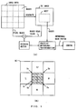
- Fig. 17 illustrates the concept of the indirect method of AC component prediction.
- the DC values of sub-blocks S 1 ⁇ S 4 in a block S of interest are estimated in accordance with the following equations from the DC values (S, U, R, B, L) of four surrounding blocks and the block of interest:
- S 1 S + (U + L - B - R)/8
- S 2 S + (U + R - B - L)/8
- S 3 S + (B + L - U - R)/8
- S 4 S + (B + R- U - L)/8
- the pixel values of four pixels P 1 ⁇ P 4 in the sub-blocks S 3 , S 4 can be estimated in a similar manner.
- the present invention has been devised in view of the problems of the prior art mentioned above and an object thereof is to provide an image coding/decoding method in which the compression rate of computer-utilizable image data is raised while the image data is maintained at a high image quality, and in which computation load at the time of decoding can be reduced, as well as a recording medium having the program of this method recorded thereon.
- an image coding method comprises dividing image data into a plurality of pixel blocks and generating a DC image comprising mean values of respective ones of the blocks; separating from each pixel block a corresponding block mean value and obtaining a residual vector for every block; and in a case where the magnitude of the residual vector becomes equal to or greater than an allowable value, obtaining one or two or more orthogonal bases for approximating the residual vector by an adaptive orthogonal transformation that employs a nest of the DC image; and coding an orthogonal base system comprising a linear combination of these orthogonal bases.
- the load upon the CPU and memory at the time of image coding/decoding is greatly alleviated by virtue of the arrangement in which one, two or more orthogonal bases are obtained from the nest of the DC image. Further, an improvement in image quality can be expected in an artificial image such as a CG image or animated image which has many flat luminance components and, as a result, exhibits strong correlation with respect to the DC image.
- the indirect method of AC component prediction or the direct method of AC component prediction according to the present invention is applied in limited fashion to the corresponding pixel block, thereby making it possible to reproduce the pixel block with little CPU and memory load.
- Q yk quantization coefficients
- third error vectors ⁇ d' 0 ⁇ ⁇ ⁇ d' 2 ⁇ which are obtained by subtracting these inverse-quantized second error vectors from respective ones of the second error vectors ⁇ d 0 ⁇ , ⁇ d 1 ⁇ , ⁇ d 2 ⁇ .
- ⁇ d' 0 ⁇ ⁇ d 0 ⁇ - ⁇ d 0
- Q' ⁇ ⁇ d' 1 ⁇ ⁇ d 1 ⁇ - ⁇ d 1
- Q' ⁇ ⁇ d' 2 ⁇ ⁇ d 2 ⁇ - ⁇ d 2 Q' ⁇ ⁇
- the magnitudes of these third error vectors ⁇ d' 0 ⁇ ⁇ ⁇ d' 2 ⁇ are not necessarily greater than the magnitude of the first error vector ⁇ d 3 ⁇ .
- the third error vector ⁇ d' 2 ⁇ gives the smallest error
- ⁇ 1 ⁇ v 1 ⁇ + ⁇ 2 ⁇ v 2 ⁇ is adopted as the orthogonal base system and these bases are coded.
- the second error vector ⁇ d 2 ⁇ is coded (scalar-quantized) conjointly.
- the quantization coefficients Q yk are decided in such a manner that the code thus generated will not exceed the total amount of code in a case where nk-number of bases are used. As a result, image quality can be improved without increasing the amount of code per pixel block.
- a recording medium according to claim (6) of the present invention is a computer-readable recording medium on which has been recorded a program for causing a computer to execute the processing described in any one of claims (1) to (5) of the present invention.
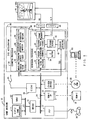
- Fig. 2 is a diagram showing the construction of an image coding/decoding system according to an embodiment and illustrating an example of application to a game machine.
- a game machine 10 proper Shown in Fig. 2 are a game machine 10 proper; a CPU (game processor) 11 for performing main control of the game machine (such as control for reading in a game program, 3D CG and texture data TXD and control for reading in data resulting from manipulation of the game by a user) and for executing game processing (such as processing for moving game characters) related to 3D CG animation; a main memory (MM) 12 comprising a RAM, ROM or EEPROM, etc., used by the CPU 11; a local (host) bus 13 of the CPU 11; a bus 14 capable of transferring data at high speed; a bridge 15 for controlling connection between the buses (and for controlling contention arbitration); a control pad 16 having various control keys (a start key, a select key and a cross-hair key, etc.) for controlling the game and setting parameters, as well as position input means such as a mouse and joystick; a peripheral interface (PIF) 17 through which the control pad 16 is accommodated in the game system; a ROM cartridge (
- a 3D accelerator 30 for subjecting input 3D CG model data to a perspective transformation on a 2D screen; a geometry processor 31; a modeling converter 32 for generating and expanding a 3D CG model of actual size comprising a set of polygons or the like at corresponding positions in 3D space in accordance with reference position data of characters and background, etc., and the shape model data thereof; a shading processor 33 for subjecting the generated model to shading that takes light (sunlight, illumination light, etc.) into consideration; a viewpoint transformation unit 34 for converting 3D CG image data in a world coordinate system XYZ to 3D CG image data in a viewpoint coordinate system xyz that is in accordance with camera viewpoint information; and a perspective transformation unit 35 for performing a perspective transformation of a generated 3D CG model in accordance with camera viewpoint information (viewpoint coordinate system xyz).
- a rendering (raster) processor 36 for executing processing synchronized to a display raster; a scanning-line analyzer 37 for extracting each item of pixel data after a perspective transformation in accordance with a scanning-line address x, y of a CRT 45; a Z buffer 38; a hidden-surface removal unit 39 which uses the Z buffer 38 to replace pixel data of a portion which should not be visible on a screen 45A by pixel data of a portion which can be seen on the screen 45A; a texture decoder 40 for decompressing (decoding) a compressed texture data input in accordance with the present invention; a texture buffer 41 for temporarily storing texture data; a texture processor 42 for pasting corresponding items of texture data in the texture buffer 41 onto each item of pixel data of the portion that can be seen on the screen 45A; a frame memory 43 for storing output color image data (R, G, B); a D/A converter (DAC) 44 for converting color pixel data in the frame memory 43 to an analog
- an external game creation unit 50 creates a game program (processing procedure, game parameters, 3D CG model data, texture data, etc.) and records the game program in the ROM cartridge 18 or CD-ROM 20.
- texture data is created, the image coding scheme according to the present invention is executed and texture data TXD that has undergone image compression is recorded in the ROM cartridge 18 or CD-ROM 20.
- the texture data TXD that has undergone image compression is decoded at high speed by the texture decoder 40, pasted to a 2D perspective image and displayed on the screen 45A.
- Image coding (compression) processing in the game creation unit 50 will be described below.
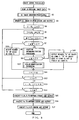
- FIGS. 3 to 7 are flowcharts (1) ⁇ (5) of image coding processing according to this embodiment
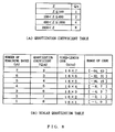
- Fig. 8 is a diagram for describing a table in this image coding processing
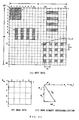
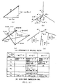
- Figs. 9 ⁇ 12 are conceptual views (1) ⁇ (4) of this image coding processing. The details of image coding processing will be described with reference to these drawings.
- the size of an original image is taken to be n pixels horizontally and m pixels vertically.
- T m,n represents partial image data obtained by extracting a square block of 4 x 4 pixels from m rows and n columns of an image T
- B y,x,sy,sx represents a block obtained by extracting data of 4 x 4, for a total of 16, pixels at steps of sx in the horizontal direction and sy in the vertical direction from y rows and x columns of a DC image.
- Fig. 3 illustrates the main processing of the image coding processing.
- Fig. 9(A) illustrates the concept of original image data.
- An image of interest in the RGB system is read in upon being converted to an image in the YUV system.
- Y corresponds to luminance data and U, V to color difference data, wherein U, V are downsampled using 2-pixel luminance averaging in the horizontal direction.
- the luminance data Y in this example comprises 960 pixels vertically x 1280 pixels horizontally, and U, V each comprise 960 pixels vertically x 640 pixels horizontally.
- eight bits are allocated to each item of pixel data of Y, U and V.
- DC-image creation processing is executed at step S2.
- This DC-image creation processing is processing for dividing the original image into blocks of 4 x 4 pixels each and creating a DC image comprising mean values M of respective ones of the blocks.
- Fig. 9(B) illustrates the concept of the DC image data DC.
- the DC image of this example comprises 240 DC values vertically x 320 DC values horizontally.
- the DC image is output upon being coded by two-dimensional DPCM at step S3.
- Fig. 10(A) illustrates the concept of two-dimensional DPCM processing.
- the DC value of row J, column I of the DC image be DC J,I .
- the symbol [a] in this case represents the result of rounding off a real number a.
- run length is taken into consideration only in a case where the predicted error ⁇ DC J,I is "0", with the predicted error ⁇ DC J,I and run length being Huffman-coded independently.
- Fig. 8(A) illustrates a table of quantization coefficients Q S .
- the values of the quantization coefficients Q S are correlated with allowable errors Z of multiple stages. The user selects the allowable error Z within a small range when high image quality is required and within a large range when low image quality is acceptable. In accordance with the selection, the quantization coefficient Q S will vary over a range of from 1 to 8.
- the address registers i,j of the original image are both initialized to "0" at step S4, and i/4, j/4 are set in the address registers I, J of the DC image at step S5.
- Fig. 10(B) illustrates the concept of the residual vector ⁇ d ⁇ . Eight bits are allocated to each element of the residual vector ⁇ d ⁇ .
- step S7 it is determined at step S7 whether the magnitude (the square) of the residual vector ⁇ d ⁇ is less than the allowable error Z. If it is less, this means that the block image data T J,I of this portion can be reconstructed with high precision on the decoding side by the direct method of AC component prediction, described later. Accordingly, control proceeds to step S18, at which the number "0" of bases is output as the code F 1 . If the residual vector is not less than the allowable error, then control proceeds to step S8, where adaptive orthogonalization processing is executed for the purpose of searching for base vectors that approximate the residual vector ⁇ d ⁇ .
- Fig. 11 illustrates the concept of adaptive orthogonalization processing.
- Adaptive orthogonalization processing is processing for finding the number nk of base vectors and each base vector ⁇ v nk ⁇ necessary to approximate the residual vector ⁇ d ⁇ within the allowable approximation error Z.
- an area of, e.g., 39 DC values vertically x 71 DC values horizontally is extracted from the DC image and adopted as a nest.
- the search for a base vector ⁇ v nk ⁇ involves setting vertex (x,y) ⁇ [0,63] x [0,31] for every DC value vertically and horizontally and adopting a total of four types of subsampling intervals, i.e., (sx,sy) ⁇ ⁇ (1,1),(1,2),(2,1),(2,2) ⁇ . This is just one example; the size of the nest, the position at which it is extracted and the subsampling intervals of the base vectors can be set at will.
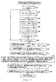
- Figs. 5 and 6 are flowcharts of adaptive orthogonalization processing according to this embodiment.
- a large value (e.g., 100000) is set in an error register E rr and a base-number register nk is initialized to "1"
- starting-address registers x, y of the nest image are both initialized to "0” at step S32
- subsample-interval registers sx, sy of the nest image are both initialized to "1" at step S33.
- a 4 x 4 DC block image B y,x,sy,sx is extracted from the nest image to create the base vector ⁇ v nk ⁇ ⁇ which corresponds to a base vector ⁇ u nk ⁇ in Fig. 11(C), described later ⁇ , and in a case where nk > 1 holds, this vector is made orthogonal to the previous base vector by Gram Schmidt orthogonalization.
- the Gram Schmidt Orthogonalization Method is a method of forming, from one base ⁇ v 1 , ⁇ , v n ⁇ of n-dimensional inner-product space V, a normal orthogonal base ( ⁇ v' 1 , ⁇ , v' n ⁇ of V.
- the Gram Schmidt Orthogonalization Method will be described in brief with reference to Fig. 11(C). Let a first base vector be represented by ⁇ v 1 ⁇ (where this corresponds to ⁇ u 1 ⁇ ).
- the scalar coefficient k in this case is If the coefficient k is substituted into the above equation, then the second orthogonal base vector ⁇ v 2 ⁇ can be expressed as follows:
- an nth normalized base vector ⁇ v' n ⁇ is expressed as follows in general:
- step S35 finds a base-vector expansion coefficient ⁇ nk that will minimize the distance to the residual vector ⁇ d ⁇ .
- the magnitude ⁇ r of an error vector which prevails when the residual vector ⁇ d ⁇ is approximated by the base vector ⁇ nk ⁇ v' nk ⁇ is obtained at step S36. It is determined at step S37 whether ⁇ r ⁇ E rr holds. If ⁇ r ⁇ E rr holds, at step S38 the ⁇ r , x, y, sx, sy prevailing at this time are retained in registers E rr , X, Y, SX, SY for storing various information relating to the minimum value of ⁇ r .
- the expansion coefficient ⁇ nk at this time is stored in a register ⁇
- the base vector ⁇ v nk ⁇ at this time is stored in a base-vector storage area v
- the orthogonalized base vector ⁇ v' nk ⁇ at this time is stored in the storage area v' of the orthogonalized base vector. Further, if ⁇ r ⁇ E rr does not hold, the processing of step S38 is skipped.
- sx>2 is finally found to hold at the discrimination step S40, sx is initialized to "1" and the sampling interval sy is incremented by +1 at step S41. It is determined at step S42 whether sy>2 holds. If sy>2 does not hold, control returns to step S34.
- step S33 If y>q does not hold, control returns to step S33 (2 ⁇ ). Now processing similar to the above is executed with regard to each base vector ⁇ v nk ⁇ of a starting position shifted by one DC value in the y direction. Processing thenceforth proceeds in similar fashion.
- base vectors ⁇ v nk ⁇ of all sampling intervals (sx,sy) ⁇ ⁇ (1,1),(1,2),(2,1),(2,2) ⁇ will have been tried with regard to all starting positions (x,y) ⁇ [0,63] x [0,31] of the nest image. Control then proceeds to step S47.
- step S47 the orthogonal base vector ⁇ v' ⁇ that has been shifted by the minimum approximation error ⁇ r is subtracted from the residual vector ⁇ d ⁇ to find the size (magnitude) of the error, and it is determined whether this size is less than the allowable error Z. If it is not less, then, at step S48, the residual vector ⁇ d ⁇ is updated by being replaced by ⁇ d ⁇ - ⁇ v' ⁇ .
- the coefficient ⁇ will be referred to as the expansion coefficient of the base vector ⁇ v ⁇ below.
- step S49 If these are replaced respectively by the transformation of step S49 will be obtained by making the replacement
- V T V a matrix (where V T represents a transposed matrix of V) from the left for the purpose of transforming the matrix V to a square matrix, thereby obtaining
- a square matrix symmetrical with respect to diagonal elements is therefore obtained and ⁇ v i ⁇ is different from ⁇ v j ⁇ .
- An inverse matrix therefore exists. Accordingly, multiplying by the inverse matrix (V T V) -1 of the matrix (V T V) from the left, we obtain
- the design is such that Gram Schmidt orthogonalization computation is no longer required at the time of decoding. Further, normalization of the norm to 1 also is eliminated.
- step S9 it is determined at step S9 whether the number of bases used nk>7 holds. If nk>7 (8 or greater) holds, there is no advantage in performing image compression even if base vectors are used. Accordingly, control proceeds to step S19, where the number "8" of bases is output as a code F 1 , the number "0" of bases used is output as a code F 2 and the residual vector ⁇ d ⁇ itself is output as a code F 3 . In case of nk ⁇ 7, control proceeds to step S10, at which scalar quantization processing set forth below is executed conjointly with use of the above-mentioned base vectors.
- the error vectors ⁇ d m ⁇ are scalar-quantized by quantization coefficients Q yk which correspond to the remaining number yk of bases, and these values are clipped in the region of values [-2 yk-1 , 2 yk-1 -1].
- Fig. 8(B) illustrates a scalar quantization table.
- the number of bases used is within the range of 0 ⁇ 7 and, in conformity therewith, the number yk of remaining bases is 7 ⁇ 1.
- Each quantization coefficient Q yk is determined beforehand in conformity with the remaining number yk of bases.
- each quantization coefficient Q yk is selected in such a manner that the error vector ⁇ d m ⁇ will fall within an amount of code equivalent to the remaining number yk of bases.
- Fig. 7 is a flowchart of scalar quantization processing.
- a register m for counting the number of bases used is initialized to "0" at step 61, and the error vector ⁇ d m ⁇ after adoption of m-number of bases is found at step S62.
- the error vector ⁇ d m ⁇ is scalar-quantized by Q yk and each element of the resulting error vector ⁇ d' m ⁇ is clipped to the range [-2 yk-1 , 2y k-1 -1] at step S64.
- the resulting error vector ⁇ d' m ⁇ (scalar-quantized and clipped) is subjected to scalar inverse quantization by the corresponding quantization coefficient Q yk at step S65.
- Error ⁇ r m at the time of comparing original error vector ⁇ d m ⁇ with said scalar inverse-quantized error vector ⁇ d'' m ⁇ is calculated, and the error ⁇ r m is memorized to predetermined storage area at step S66.
- the register m is incremented by +1 at step S67 and it is determined at step S68 whether m>nk (1 ⁇ nk ⁇ 7) holds. If m>nk does not hold, control returns to step S62 and executes processing similar to the foregoing.
- the starting position (x,y), in the nest, of each base used, the subsampling interval (sx,sy) and the remainder obtained by quantizing the expansion coefficient ⁇ of each base used by Q (e.g., 8) are packed into 16 bits for every base and output as a code F 4 at step S72.
- the breakdown of the code F 4 is as follows: six bits horizontally and five bits vertically, for a total of 11 bits, for the starting position (x,y) in the nest, two bits for the subsampling interval of any of four types, and three bits for the remainder of the expansion coefficient ⁇ , for a grand total of 16 bits. Accordingly, the code F 4 consumes two bytes for every base used.
- the expansion coefficients ⁇ of the bases are quantized by Q (e.g., 8) and output its quotient as a code F 5 at step S73.
- Error vectors ⁇ d' mk ⁇ at minimum inverse quantization error ⁇ r mk are allocated to an area of 16 x (nk - mk) bits equivalent to the remaining number yk of bases and are output as a code F 3 . Processing is then exited.
- step S12 coding of one residual vector ⁇ d ⁇ of the original image is thus completed.
- the address register i is incremented by +4 at step S11 and it is determined at step S12 whether i>n holds. If i>n does not hold, control returns to step S5 and coding is performed by executing processing similar to the foregoing with regard to one residual vector ⁇ d ⁇ from a position that has been shifted four bits along the i axis. Control thenceforth proceeds in the same manner.
- step S5 If j>m does not hold, control returns to step S5 and coding is performed by executing processing similar to the foregoing with regard to each residual vector ⁇ d ⁇ shifted four bits along the j axis. Control thenceforth proceeds in the same manner.
- step S14 the above-described coding processing ends for all residual vectors ⁇ d ⁇ of the image.
- Fig. 12(B) illustrates image compression code. This table will be referred to in the description given below.
- variable-length codes F 1 , F 2 , F 5 are Huffman coded and output at step S15.
- Q e.g. 8
- the code F 5 the quotient obtained by quantizing the expansion coefficient ⁇ by the constant Q (e.g., 8) is Huffman coded.
- a code EOB for indicating changeover of the image block is written in.
- variable-length code F 6 is Huffman coded and output at step S16.
- variable-length code F 3 and fixed-length code F 4 are Huffman coded and output at step S17.
- the code F4 is fixed at a total of 16 bits per base, namely 11 bits for the starting coordinates (x,y) of the nest, two bits for the subsampling coefficients (sx,sy) and three bits for the remainder ( ⁇ /Q) of the expansion coefficient ⁇ . These bits are packed in the order in which the bases used appear.
- a code string is constructed as the overall code by packing code in the order of appearance in pixel block units.
- the number nk of bases is around two in more than half the blocks and the small number of variable-length codes obtained are only the quotient which is the result of quantizing the expansion coefficient ⁇ of the base by Q, DPCM code of the DC image, the number "nk” of bases and the number "mk” of bases used.
- Fig. 13 is a flowchart of image decoding processing according to this embodiment.
- Image code data is read in at step S81 and the DC values of Y, U, V are decompressed (decoded) at step S82.
- a nest is generated from the DC values of the Y component at step S83. The nest can be generated upon separately receiving starting-position and size information of the DC image.
- Address registers i, j of the decoded (reproduced) image are both initialized to "0" at step S84.
- step S89 mk-number of base vectors are created from the nest in accordance with the starting position (x,y) of each base and the subsampling interval (sx,sy), the products between the vectors and the expansion coefficients ⁇ are obtained, an approximation vector (orthogonal base system) comprising a linear combination of these products is formed and the error vector ⁇ d' mk ⁇ is combined with the approximation vector to reproduce the original residual vector ⁇ d ⁇ .
- the decoded DC value is added to the obtained residual vector ⁇ d ⁇ at step S90.
- the 4 x 4 block image T j,i is thus reproduced by any method described above.
- the reproduced image T j,i is stored in an image memory at step S91.
- step S93 The address register is incremented by +4 at step S92 and it is determined at step S93 whether i>n holds. If i>n does not hold, control returns to step S85. Now the block image data T j,i of the next column is decoded and stored in the image memory. Control thenceforth proceeds in the same manner.
- Fig. 14 is a conceptual view of direct AC component prediction processing according to this embodiment.
- approximation images (AC images) of an original pixel block are generated at a stroke from the neighboring DC image by the direct method of AC component prediction.
- the DC values of sub-blocks S 1 ⁇ S 4 in a block S of interest are estimated in accordance with the following equations from the DC values (S, U, R, B, L) of four surrounding blocks and the block of interest:
- S 1 S + (U + L - B - R)/8
- S 2 S + (U + R - B - L)/8
- S 3 S + (B + L - U - R)/8
- S 4 S + (B + R - U - L)/8
- Fig. 14(A) illustrates again a diagram similar to that of Fig. 17(B) described above.
- U 1 ⁇ U 4 , L 1 ⁇ L 4 , R 1 ⁇ R 4 , B 1 ⁇ B 4 are estimated in the first stage.
- Fig. 14B illustrates the direction method of AC component prediction according to this embodiment. Reference will be had to Fig. 14(A) as well in the description that follows. First, in a case where four pixels P 1 ⁇ P 4 in S 1 are found, the approximations S 2 ⁇ S 3 ⁇ S, U 3 ⁇ U, L 2 ⁇ L are performed.
- Fig. 15 is a graph of coding efficiency according to this embodiment.
- PSNR [dB] 20log 10 (255/ ⁇ ( ⁇ 2 ))
- BPR [total amount of data (bits) after compression)/[number of pixels in original image]
- BPR represents bits per pixel
- PSNR represents peak-to-peak signal-to-noise ratio.
- ⁇ 2 represents mean square error per pixel.
- the nest can be lightened and the amount of variable-length code reduced, the computation load at the time of decoding can be reduced and it is possible to utilize moving-picture and still-picture image data, without degrading image quality, even in a system having a comparatively low performance.
- mosquito noise is not produced even at contours and it is possible to provide highly compressed image data featuring good reproducibility in regard to characters and animated images.
Landscapes
- Engineering & Computer Science (AREA)
- Multimedia (AREA)
- Signal Processing (AREA)
- Physics & Mathematics (AREA)
- Discrete Mathematics (AREA)
- General Physics & Mathematics (AREA)
- Compression Or Coding Systems Of Tv Signals (AREA)
- Compression, Expansion, Code Conversion, And Decoders (AREA)
Applications Claiming Priority (3)
| Application Number | Priority Date | Filing Date | Title |
|---|---|---|---|
| JP18923998 | 1998-07-03 | ||
| JP18923998 | 1998-07-03 | ||
| PCT/JP1999/002962 WO2000002393A1 (fr) | 1998-07-03 | 1999-06-03 | Procede de codage et decodage d'images et support sur lequel est enregistre un programme |
Publications (2)
| Publication Number | Publication Date |
|---|---|
| EP1104199A1 true EP1104199A1 (fr) | 2001-05-30 |
| EP1104199A4 EP1104199A4 (fr) | 2008-04-02 |
Family
ID=16237951
Family Applications (1)
| Application Number | Title | Priority Date | Filing Date |
|---|---|---|---|
| EP99923879A Withdrawn EP1104199A4 (fr) | 1998-07-03 | 1999-06-03 | Procede de codage et decodage d'images et support sur lequel est enregistre un programme |
Country Status (8)
| Country | Link |
|---|---|
| US (1) | US6687411B1 (fr) |
| EP (1) | EP1104199A4 (fr) |
| JP (1) | JP3814637B2 (fr) |
| KR (1) | KR100574702B1 (fr) |
| CN (1) | CN1168322C (fr) |
| CA (1) | CA2347383A1 (fr) |
| TW (1) | TW440805B (fr) |
| WO (1) | WO2000002393A1 (fr) |
Cited By (1)
| Publication number | Priority date | Publication date | Assignee | Title |
|---|---|---|---|---|
| EP1156679A3 (fr) * | 2000-05-15 | 2003-10-08 | Hudson Soft Co., Ltd. | Méthode et appareil de codage et de décodage d'image, et support d'enregistrement sur lequel est enregistré le programme correspondant |
Families Citing this family (21)
| Publication number | Priority date | Publication date | Assignee | Title |
|---|---|---|---|---|
| JP3496559B2 (ja) * | 1999-01-06 | 2004-02-16 | 日本電気株式会社 | 画像特徴量生成装置、並びに画像特徴量生成方法 |
| JP4649760B2 (ja) * | 2000-05-31 | 2011-03-16 | ソニー株式会社 | コンテンツ・コピー管理システム及び方法、情報処理装置及び方法、並びに、記憶媒体 |
| JP3887178B2 (ja) | 2001-04-09 | 2007-02-28 | 株式会社エヌ・ティ・ティ・ドコモ | 信号符号化方法及び装置並びに復号方法及び装置 |
| JP4570065B2 (ja) * | 2001-04-13 | 2010-10-27 | Kddi株式会社 | 適応直交変換符号化装置 |
| US6944333B2 (en) * | 2003-04-30 | 2005-09-13 | Ventana Medical Systems, Inc. | Color image compression via spectral decorrelation and elimination of spatial redundancy |
| US7640370B1 (en) * | 2003-11-25 | 2009-12-29 | Marvell International Ltd. | Method and apparatus for controlling data transfer between EEPROM and a physical layer device |
| SE0401850D0 (sv) * | 2003-12-19 | 2004-07-08 | Ericsson Telefon Ab L M | Image processing |
| SE526226C2 (sv) * | 2003-12-19 | 2005-08-02 | Ericsson Telefon Ab L M | Bildbehandling |
| JP4684147B2 (ja) * | 2006-03-28 | 2011-05-18 | 任天堂株式会社 | 傾き算出装置、傾き算出プログラム、ゲーム装置およびゲームプログラム |
| US7787691B2 (en) * | 2006-04-11 | 2010-08-31 | Telefonaktiebolaget Lm Ericsson (Publ) | High quality image processing |
| CA2683841A1 (fr) * | 2007-04-04 | 2008-10-16 | Telefonaktiebolaget Lm Ericsson (Publ) | Traitement d'image vectoriel |
| JP5686499B2 (ja) * | 2009-01-22 | 2015-03-18 | 株式会社Nttドコモ | 画像予測符号化装置、方法及びプログラム、画像予測復号装置、方法及びプログラム、並びに、符号化・復号システム及び方法 |
| US8787698B2 (en) | 2009-09-04 | 2014-07-22 | Adobe Systems Incorporated | Methods and apparatus for directional texture generation using image warping |
| US8619098B2 (en) | 2009-09-18 | 2013-12-31 | Adobe Systems Incorporated | Methods and apparatuses for generating co-salient thumbnails for digital images |
| US8599219B2 (en) | 2009-09-18 | 2013-12-03 | Adobe Systems Incorporated | Methods and apparatuses for generating thumbnail summaries for image collections |
| WO2011099789A2 (fr) * | 2010-02-10 | 2011-08-18 | 엘지전자 주식회사 | Procédé et appareil de traitement de signaux vidéo |
| US8861868B2 (en) | 2011-08-29 | 2014-10-14 | Adobe-Systems Incorporated | Patch-based synthesis techniques |
| US9819964B2 (en) | 2012-05-04 | 2017-11-14 | Environmental Systems Research Institute, Inc. | Limited error raster compression |
| US9002126B2 (en) | 2012-05-04 | 2015-04-07 | Environmental Systems Research Institute (ESRI) | Limited error raster compression |
| CN103581677B (zh) * | 2012-07-20 | 2017-02-15 | 中国科学院深圳先进技术研究院 | 图像加密压缩和解压解密方法及装置 |
| US9256709B2 (en) | 2014-02-13 | 2016-02-09 | Taiwan Semiconductor Manufacturing Company, Ltd. | Method for integrated circuit mask patterning |
Family Cites Families (7)
| Publication number | Priority date | Publication date | Assignee | Title |
|---|---|---|---|---|
| JPH0738760A (ja) | 1993-06-28 | 1995-02-07 | Nec Corp | 直交変換基底生成方式 |
| US6456655B1 (en) * | 1994-09-30 | 2002-09-24 | Canon Kabushiki Kaisha | Image encoding using activity discrimination and color detection to control quantizing characteristics |
| US5937098A (en) * | 1995-02-06 | 1999-08-10 | Asahi Kogaku Kogyo Kabushiki Kaisha | Adaptive quantization of orthogonal transform coefficients for setting a target amount of compression |
| KR0174453B1 (ko) * | 1995-02-28 | 1999-03-20 | 배순훈 | 디지털 영상 복호화 방법 |
| KR0174452B1 (ko) * | 1995-02-28 | 1999-03-20 | 배순훈 | 디지털 영상 복호화장치 |
| US6115070A (en) * | 1997-06-12 | 2000-09-05 | International Business Machines Corporation | System and method for DCT domain inverse motion compensation using shared information |
| JPH11196262A (ja) * | 1997-11-07 | 1999-07-21 | Matsushita Electric Ind Co Ltd | デジタル情報埋込み・抽出装置および方法並びに当該方法を実行するためのプログラムを記録した媒体 |
-
1999
- 1999-06-03 EP EP99923879A patent/EP1104199A4/fr not_active Withdrawn
- 1999-06-03 CA CA002347383A patent/CA2347383A1/fr not_active Abandoned
- 1999-06-03 CN CNB998080128A patent/CN1168322C/zh not_active Expired - Fee Related
- 1999-06-03 WO PCT/JP1999/002962 patent/WO2000002393A1/fr not_active Ceased
- 1999-06-03 JP JP2000558674A patent/JP3814637B2/ja not_active Expired - Lifetime
- 1999-06-03 KR KR1020007015005A patent/KR100574702B1/ko not_active Expired - Lifetime
- 1999-06-03 US US09/720,551 patent/US6687411B1/en not_active Expired - Fee Related
- 1999-06-08 TW TW88109553A patent/TW440805B/zh not_active IP Right Cessation
Non-Patent Citations (4)
| Title |
|---|
| CAGLAR H ET AL: "VQ-ADAPTIVE BLOCK TRANSFORM CODING OF IMAGES" IEEE TRANSACTIONS ON IMAGE PROCESSING, IEEE SERVICE CENTER, PISCATAWAY, NJ, US, vol. 7, no. 1, January 1998 (1998-01), pages 110-115, XP000727379 ISSN: 1057-7149 * |
| HURD L P ET AL: "FRACTAL VIDEO COMPRESSION" INTELLECTUAL LEVERAGE. SAN FRANCISCO, FEB. 24 - 28, 1992, PROCEEDINGS OF THE COMPUTER SOCIETY INTERNATIONAL CONFERENCE (COMPCON)SPRING, LOS ALAMITOS, IEEE COMP. SOC. PRESS, US, vol. CONF. 37, 24 February 1992 (1992-02-24), pages 41-42, XP000340714 ISBN: 0-8186-2655-0 * |
| See also references of WO0002393A1 * |
| YOU HYUNBEA ET AL: "Improving LIFS Image Coding Scheme by Applying Gram Schmidt Orthogonalization" DENSHI JOHO TSUSHIN GAKKAI GIJUTSU KUNKYU HOKOKU - IEICE TECHNICAL REPORT, DENSHI JOHO TSUSHIN GAKKAI, TOKYO, JP, vol. NLP-98, no. 146, June 1998 (1998-06), pages 37-42, XP008087933 ISSN: 0913-5685 * |
Cited By (3)
| Publication number | Priority date | Publication date | Assignee | Title |
|---|---|---|---|---|
| EP1156679A3 (fr) * | 2000-05-15 | 2003-10-08 | Hudson Soft Co., Ltd. | Méthode et appareil de codage et de décodage d'image, et support d'enregistrement sur lequel est enregistré le programme correspondant |
| US6714687B2 (en) | 2000-05-15 | 2004-03-30 | Hudson Soft Co., Ltd. | Image encoding/decoding method, apparatus thereof and recording medium in which program therefor is recorded |
| US7231089B2 (en) | 2000-05-15 | 2007-06-12 | Hudson Soft Co. Ltd. | Image encoding/decoding method, apparatus thereof and recording medium in which program therefor is recorded |
Also Published As
| Publication number | Publication date |
|---|---|
| TW440805B (en) | 2001-06-16 |
| US6687411B1 (en) | 2004-02-03 |
| CA2347383A1 (fr) | 2000-01-13 |
| KR20010053286A (ko) | 2001-06-25 |
| JP3814637B2 (ja) | 2006-08-30 |
| CN1307782A (zh) | 2001-08-08 |
| EP1104199A4 (fr) | 2008-04-02 |
| HK1036377A1 (en) | 2001-12-28 |
| WO2000002393A1 (fr) | 2000-01-13 |
| CN1168322C (zh) | 2004-09-22 |
| KR100574702B1 (ko) | 2006-04-27 |
Similar Documents
| Publication | Publication Date | Title |
|---|---|---|
| US6687411B1 (en) | Image coding/decoding method and recording medium having program for this method recorded thereon | |
| US7848580B2 (en) | Image encoding method, image decoding method, moving-image compression method, moving-image expansion method, image encoding program, image decoding device, image encoding device, image encoding/decoding system, and extended image compression/expansion system | |
| JP3681386B2 (ja) | 改良されたベクトルの量子化のための前処理及び後処理 | |
| US5510838A (en) | Apparatus and method for picture representation by data compression | |
| JP5722761B2 (ja) | 動画圧縮装置、画像処理装置、動画圧縮方法、画像処理方法、および動画圧縮ファイルのデータ構造 | |
| JPWO2000002393A1 (ja) | 画像符号/復号方法及びそのプログラムを記録した記録媒体 | |
| JP3356663B2 (ja) | 画像符号化装置、画像符号化方法および画像符号化プログラムを記録した記録媒体 | |
| EP0559982A2 (fr) | Compression d'images | |
| EP0871336A2 (fr) | Méthode et appareil de codage et décodage prédictif d'image | |
| EP0838953A2 (fr) | Méthode de remplissage d'un signal d'image aux fins de codage/décodage | |
| US7177356B2 (en) | Spatially transcoding a video stream | |
| WO2000060847A1 (fr) | Compression d'images | |
| KR20040010722A (ko) | 구성가능한 패턴 옵티마이저 | |
| JP3530125B2 (ja) | 構造化ポリゴン・メッシュ・データの形成方法および装置、記憶媒体 | |
| US5915046A (en) | System for and method of processing digital images | |
| JP2001186516A (ja) | 画像データの符号化復号化方法及び装置 | |
| JPH07177502A (ja) | 画像情報圧縮方法、圧縮画像情報記録媒体、圧縮画像情報再生装置 | |
| JP2007527126A (ja) | 画像部分の圧縮方法および装置 | |
| TWI856179B (zh) | 影像編碼裝置及其控制方法、以及影像解碼裝置及其控制方法 | |
| TWI803709B (zh) | 圖像編碼裝置、圖像解碼裝置、其等之控制方法及程式 | |
| KR980013427A (ko) | 영상 코딩 장치, 영상 코딩 방법, 영상 디코딩 방법,영상 디코딩 장치, 영상 데이터 전송 방법 및 기록 매체(Image Coding Apparatus, Image Coding Method, Image Decoding Method, Image Decofing Apparatus, Image Data Transmitting Method and Recording Medium) | |
| US5915043A (en) | Image reproducing apparatus | |
| JP3158064B2 (ja) | 動画像符号化装置及び動画像復号装置 | |
| JPH11136674A (ja) | 画像符号化方法及び記憶媒体 | |
| JP2002369201A (ja) | 画像データ圧縮装置、画像データ圧縮方法、記録媒体およびプログラム |
Legal Events
| Date | Code | Title | Description |
|---|---|---|---|
| PUAI | Public reference made under article 153(3) epc to a published international application that has entered the european phase |
Free format text: ORIGINAL CODE: 0009012 |
|
| 17P | Request for examination filed |
Effective date: 20001227 |
|
| AK | Designated contracting states |
Kind code of ref document: A1 Designated state(s): DE FR GB NL |
|
| A4 | Supplementary search report drawn up and despatched |
Effective date: 20080228 |
|
| RIC1 | Information provided on ipc code assigned before grant |
Ipc: H04N 7/30 20060101AFI20000118BHEP |
|
| 17Q | First examination report despatched |
Effective date: 20090220 |
|
| STAA | Information on the status of an ep patent application or granted ep patent |
Free format text: STATUS: THE APPLICATION IS DEEMED TO BE WITHDRAWN |
|
| 18D | Application deemed to be withdrawn |
Effective date: 20101029 |