EP1104522B1 - Ventil betätigt über gasdruckbehälter - Google Patents
Ventil betätigt über gasdruckbehälter Download PDFInfo
- Publication number
- EP1104522B1 EP1104522B1 EP99945059A EP99945059A EP1104522B1 EP 1104522 B1 EP1104522 B1 EP 1104522B1 EP 99945059 A EP99945059 A EP 99945059A EP 99945059 A EP99945059 A EP 99945059A EP 1104522 B1 EP1104522 B1 EP 1104522B1
- Authority
- EP
- European Patent Office
- Prior art keywords
- valve
- piston
- gate
- gate member
- cartridge
- Prior art date
- Legal status (The legal status is an assumption and is not a legal conclusion. Google has not performed a legal analysis and makes no representation as to the accuracy of the status listed.)
- Expired - Lifetime
Links
- 238000002955 isolation Methods 0.000 title claims abstract description 16
- 230000000694 effects Effects 0.000 claims abstract description 5
- 238000013459 approach Methods 0.000 claims abstract description 3
- 238000002485 combustion reaction Methods 0.000 claims description 10
- 230000001413 cellular effect Effects 0.000 claims description 5
- 238000000034 method Methods 0.000 claims description 4
- 230000035939 shock Effects 0.000 claims description 3
- 238000004891 communication Methods 0.000 claims description 2
- 239000007789 gas Substances 0.000 description 24
- 239000003380 propellant Substances 0.000 description 18
- 239000000203 mixture Substances 0.000 description 8
- 210000004027 cell Anatomy 0.000 description 6
- 238000006073 displacement reaction Methods 0.000 description 5
- 239000002360 explosive Substances 0.000 description 5
- 230000001133 acceleration Effects 0.000 description 4
- 238000009472 formulation Methods 0.000 description 4
- 239000000843 powder Substances 0.000 description 4
- 230000007704 transition Effects 0.000 description 4
- 238000004200 deflagration Methods 0.000 description 3
- AXZAYXJCENRGIM-UHFFFAOYSA-J dipotassium;tetrabromoplatinum(2-) Chemical compound [K+].[K+].[Br-].[Br-].[Br-].[Br-].[Pt+2] AXZAYXJCENRGIM-UHFFFAOYSA-J 0.000 description 3
- 238000004880 explosion Methods 0.000 description 3
- 239000012530 fluid Substances 0.000 description 3
- 239000003999 initiator Substances 0.000 description 3
- 229910001487 potassium perchlorate Inorganic materials 0.000 description 3
- IJGRMHOSHXDMSA-UHFFFAOYSA-N Atomic nitrogen Chemical compound N#N IJGRMHOSHXDMSA-UHFFFAOYSA-N 0.000 description 2
- 239000000020 Nitrocellulose Substances 0.000 description 2
- SNIOPGDIGTZGOP-UHFFFAOYSA-N Nitroglycerin Chemical compound [O-][N+](=O)OCC(O[N+]([O-])=O)CO[N+]([O-])=O SNIOPGDIGTZGOP-UHFFFAOYSA-N 0.000 description 2
- 239000000006 Nitroglycerin Substances 0.000 description 2
- 229910000831 Steel Inorganic materials 0.000 description 2
- FJWGYAHXMCUOOM-QHOUIDNNSA-N [(2s,3r,4s,5r,6r)-2-[(2r,3r,4s,5r,6s)-4,5-dinitrooxy-2-(nitrooxymethyl)-6-[(2r,3r,4s,5r,6s)-4,5,6-trinitrooxy-2-(nitrooxymethyl)oxan-3-yl]oxyoxan-3-yl]oxy-3,5-dinitrooxy-6-(nitrooxymethyl)oxan-4-yl] nitrate Chemical compound O([C@@H]1O[C@@H]([C@H]([C@H](O[N+]([O-])=O)[C@H]1O[N+]([O-])=O)O[C@H]1[C@@H]([C@@H](O[N+]([O-])=O)[C@H](O[N+]([O-])=O)[C@@H](CO[N+]([O-])=O)O1)O[N+]([O-])=O)CO[N+](=O)[O-])[C@@H]1[C@@H](CO[N+]([O-])=O)O[C@@H](O[N+]([O-])=O)[C@H](O[N+]([O-])=O)[C@H]1O[N+]([O-])=O FJWGYAHXMCUOOM-QHOUIDNNSA-N 0.000 description 2
- 230000000712 assembly Effects 0.000 description 2
- 238000000429 assembly Methods 0.000 description 2
- 210000003850 cellular structure Anatomy 0.000 description 2
- 230000002596 correlated effect Effects 0.000 description 2
- 230000000875 corresponding effect Effects 0.000 description 2
- 238000013461 design Methods 0.000 description 2
- 229960003711 glyceryl trinitrate Drugs 0.000 description 2
- 231100001261 hazardous Toxicity 0.000 description 2
- 239000011133 lead Substances 0.000 description 2
- VRNINGUKUJWZTH-UHFFFAOYSA-L lead(2+);dithiocyanate Chemical compound [Pb+2].[S-]C#N.[S-]C#N VRNINGUKUJWZTH-UHFFFAOYSA-L 0.000 description 2
- 229920001220 nitrocellulos Polymers 0.000 description 2
- 229920001084 poly(chloroprene) Polymers 0.000 description 2
- 230000000750 progressive effect Effects 0.000 description 2
- 239000010959 steel Substances 0.000 description 2
- 239000010963 304 stainless steel Substances 0.000 description 1
- 229910000589 SAE 304 stainless steel Inorganic materials 0.000 description 1
- 230000002411 adverse Effects 0.000 description 1
- 230000000903 blocking effect Effects 0.000 description 1
- 230000015556 catabolic process Effects 0.000 description 1
- 238000001311 chemical methods and process Methods 0.000 description 1
- 239000000470 constituent Substances 0.000 description 1
- 238000010276 construction Methods 0.000 description 1
- 238000011109 contamination Methods 0.000 description 1
- 238000006731 degradation reaction Methods 0.000 description 1
- 230000002939 deleterious effect Effects 0.000 description 1
- 230000001419 dependent effect Effects 0.000 description 1
- 238000009826 distribution Methods 0.000 description 1
- 229920001971 elastomer Polymers 0.000 description 1
- 239000000806 elastomer Substances 0.000 description 1
- 230000007613 environmental effect Effects 0.000 description 1
- 238000013467 fragmentation Methods 0.000 description 1
- 238000006062 fragmentation reaction Methods 0.000 description 1
- 239000008187 granular material Substances 0.000 description 1
- 230000003116 impacting effect Effects 0.000 description 1
- 238000009434 installation Methods 0.000 description 1
- 238000004519 manufacturing process Methods 0.000 description 1
- 239000000463 material Substances 0.000 description 1
- 229910052757 nitrogen Inorganic materials 0.000 description 1
- 229920003023 plastic Polymers 0.000 description 1
- 229920005989 resin Polymers 0.000 description 1
- 239000011347 resin Substances 0.000 description 1
- 238000007789 sealing Methods 0.000 description 1
- 239000007787 solid Substances 0.000 description 1
- 239000004449 solid propellant Substances 0.000 description 1
- 238000003860 storage Methods 0.000 description 1
- 239000000126 substance Substances 0.000 description 1
- 238000012360 testing method Methods 0.000 description 1
- 238000012546 transfer Methods 0.000 description 1
- 238000013022 venting Methods 0.000 description 1
Images



Classifications
-
- F—MECHANICAL ENGINEERING; LIGHTING; HEATING; WEAPONS; BLASTING
- F16—ENGINEERING ELEMENTS AND UNITS; GENERAL MEASURES FOR PRODUCING AND MAINTAINING EFFECTIVE FUNCTIONING OF MACHINES OR INSTALLATIONS; THERMAL INSULATION IN GENERAL
- F16K—VALVES; TAPS; COCKS; ACTUATING-FLOATS; DEVICES FOR VENTING OR AERATING
- F16K3/00—Gate valves or sliding valves, i.e. cut-off apparatus with closing members having a sliding movement along the seat for opening and closing
- F16K3/02—Gate valves or sliding valves, i.e. cut-off apparatus with closing members having a sliding movement along the seat for opening and closing with flat sealing faces; Packings therefor
- F16K3/0254—Gate valves or sliding valves, i.e. cut-off apparatus with closing members having a sliding movement along the seat for opening and closing with flat sealing faces; Packings therefor being operated by particular means
-
- F—MECHANICAL ENGINEERING; LIGHTING; HEATING; WEAPONS; BLASTING
- F16—ENGINEERING ELEMENTS AND UNITS; GENERAL MEASURES FOR PRODUCING AND MAINTAINING EFFECTIVE FUNCTIONING OF MACHINES OR INSTALLATIONS; THERMAL INSULATION IN GENERAL
- F16K—VALVES; TAPS; COCKS; ACTUATING-FLOATS; DEVICES FOR VENTING OR AERATING
- F16K13/00—Other constructional types of cut-off apparatus; Arrangements for cutting-off
- F16K13/04—Other constructional types of cut-off apparatus; Arrangements for cutting-off with a breakable closure member
- F16K13/06—Other constructional types of cut-off apparatus; Arrangements for cutting-off with a breakable closure member constructed to be ruptured by an explosion
-
- Y—GENERAL TAGGING OF NEW TECHNOLOGICAL DEVELOPMENTS; GENERAL TAGGING OF CROSS-SECTIONAL TECHNOLOGIES SPANNING OVER SEVERAL SECTIONS OF THE IPC; TECHNICAL SUBJECTS COVERED BY FORMER USPC CROSS-REFERENCE ART COLLECTIONS [XRACs] AND DIGESTS
- Y10—TECHNICAL SUBJECTS COVERED BY FORMER USPC
- Y10T—TECHNICAL SUBJECTS COVERED BY FORMER US CLASSIFICATION
- Y10T137/00—Fluid handling
- Y10T137/0318—Processes
-
- Y—GENERAL TAGGING OF NEW TECHNOLOGICAL DEVELOPMENTS; GENERAL TAGGING OF CROSS-SECTIONAL TECHNOLOGIES SPANNING OVER SEVERAL SECTIONS OF THE IPC; TECHNICAL SUBJECTS COVERED BY FORMER USPC CROSS-REFERENCE ART COLLECTIONS [XRACs] AND DIGESTS
- Y10—TECHNICAL SUBJECTS COVERED BY FORMER USPC
- Y10T—TECHNICAL SUBJECTS COVERED BY FORMER US CLASSIFICATION
- Y10T137/00—Fluid handling
- Y10T137/1624—Destructible or deformable element controlled
-
- Y—GENERAL TAGGING OF NEW TECHNOLOGICAL DEVELOPMENTS; GENERAL TAGGING OF CROSS-SECTIONAL TECHNOLOGIES SPANNING OVER SEVERAL SECTIONS OF THE IPC; TECHNICAL SUBJECTS COVERED BY FORMER USPC CROSS-REFERENCE ART COLLECTIONS [XRACs] AND DIGESTS
- Y10—TECHNICAL SUBJECTS COVERED BY FORMER USPC
- Y10T—TECHNICAL SUBJECTS COVERED BY FORMER US CLASSIFICATION
- Y10T137/00—Fluid handling
- Y10T137/1624—Destructible or deformable element controlled
- Y10T137/1632—Destructible element
- Y10T137/1647—Explosive actuation
Definitions
- This invention relates to improved gate valve apparatus of the type commonly used in association with chemical processes or the like which may experience a hazard condition or upset requiring rapid valve actuation to prevent a catastrophic failure. More particularly, the invention relates to a gate valve apparatus provided with an actuator which generates a gas discharge at a subsonic flow rate in order to rapidly and smoothly shift a valve member for actuation of the gate valve apparatus. Structure is also provided in association with the valve member to control the rate of deceleration of the gate valve.
- Isolation-type gate valves have long been provided with chemical reactor apparatus for the purpose of allowing rapid shutdown of the reactor in the event of generation of hazardous conditions.
- such gate valves include a valve body which presents a passageway therethrough, with a shiftable, apertured valve member within the body and normally located in a valve open position allowing flow through the valve.
- the valve member is shiftable to a flow-blocking valve closed position when a hazardous condition is sensed.
- prior gate valves have included mechanical linkages operated by motors or solenoids for example.
- prior actuators are unable to actuate a gate valve with sufficient rapidity to prevent flame propagation, actual passage of a flame through the gate, explosion, or some other significant failure.
- US-A-3,494,370 discloses a normally closed valve which can be driven to an open position by explosive force. When the explosive force fires, a piston moves a piston rod downwardly, thereby breaking an end wall cleanly and without fragmentation so that the valve has opened.
- EP-A-0 062 552 discloses a gate valve which does not a gas cartridge generated charge of 5-8 m/sec, and therefore a value less than mach 1 or 331 m/sec
- the time of closing of the plate 13 in D2 (.30 5 m/sec) (D2, p, 6) is 4 to 5 times faster than the closing of the gate in applicant's claimed invention (5-8 m/sec).
- US-A-5,205,069 discloses use of an explosive bolt that allows a door to be closed. Pre-pressurized nitrogen is employed to close the door, not a CAD. No mention is made of component operating times, or the provision of a CAD.
- US-A-4,619,284 discloses a pyrotechnic valve whit devices 40 are said to produce a large amount of gas under high pressure, but no mention is made of the use of a CAD.
- US-A-3,358,961 represents another type of gate valve for releasing pressure in a fluid flow system.
- a sliding valve is operated by an explosive charge producing a supersonic shock wave for extreme accelerated shifting of the valve body from a normally closed position to a fully opened location.
- the shutter-type valve is useful only for relatively small orifice applications involving a similarly limited size valve assembly.
- the valve body and associated shutter plate and piston assembly must be small enough that no damage is caused to the valve components by shock waves generated upon actuation of the explosive device, or as a result of inertia upon impact of the shutter plate with the housing assembly during valve closing.
- Gate valves of the type in which the present invention is most useful are generally employed to either close off a tubular passage upon actuation, or to open that passageway.
- the aperture of the gate valve which is either closed by the gate, or is opened upon shifting of the gate, is essentially of the same cross-sectional dimensions as the passageway. For example, if the passage is defined by a 20,32 cm (8-inch) pipe, the aperture in the gate valve should also have a diameter of 20,32 cm (8 inches).
- the present invention provides an improved isolation gate valve assembly as claimed in claim 1 and a method as claimed in claim 9.
- the claimed assembly is especially useful in a wide variety of sizes of gate valves, in which the aperture therethrough can be anywhere from about 50.8 mm (2 inches) up to as much as 609.6 mm (24 inches) or more.
- the isolation valve has particular utility in larger size applications involving pipes having a diameter of 152.4 mm (6 inches) or more.
- those of the invention include a valve body presenting a passageway therethrough, a gate unit including a shiftable, apertured gate member proximal to the passageway and shiftable from a valve open position wherein the valve member aperture is in registry with the valve passageway, and a valve closed position wherein the gate member aperture is out of registry with the passageway.
- the improved actuator of the invention has components which function to rapidly shift the gate valve at a predetermined, controlled acceleration between the positions thereof, i.e., from the valve open to the valve closed position, or from the valve closed to the valve open position, and to control the deceleration of the gate member in a predetermined manner as it approaches it open or closed position.
- a gas-generating cartridge unit is provided to generate a subsonic charge of pressurized gas to selectively open or close the gate member as the case may be.
- the gate member is responsive to such pressurized gas for shifting thereof at a velocity of from 5.1 meters per second (0.2 in./msec) to 8.4 meters per second (0.33 in./ms), depending upon the size of the gate valve with the time of actuation within the preferred range being a function of and longer in time for larger pipe diameters.
- Significantly faster closing times can cause damage to valve components as a result of impact of the gate valve with the housing for the gate valve, and slower closing can cause the valve to fail in its function of preventing flame fronts or gaseous production of combustion from the source of the deflagration to an unprotected area.
- the actuator includes a tubular housing, a piston shiftable within the housing and having an elongated piston rod coupled between the piston and the gas member.
- a gas-generating cartridge is connected to the tubular housing in disposition defining an expandable pressurized gas-receiving chamber between the piston and the gas discharge end of the cartridge.
- the gas-generating cartridge unit is located for directing a charge of subsonic pressurized gas into the housing and against the face of the piston remote from the rod to thereby shift the piston within the housing and correspondingly shift the gate member.
- the preferred gas-generating cartridge unit is in the form of an elongated cartridge body oriented in either a transverse or aligned relationship with the housing and having an outlet; the cartridge has a quantity of solid, ignitable propellant within the chamber which upon ignition burns at a controlled rate producing a flow of pressurized gaseous products of combustion which flow into the chamber at a rate that does not exceed a velocity of about 331 meters per second (mach 1).
- An appropriate ignitor and electrical lead structure extend from the chamber and are operably coupled with the propellant for ignition thereof. Either single or multiple gas-generating cartridge units may be used as required for a particular application.
- a dampener unit is associated with the gate valve in a location to be engaged by the valve as it reaches its closed position to provide controlled deceleration of the gate valve, thereby preventing bouncing of the valve and also guard against untoward impact forces being directed to the housing for the valve by the gate valve body itself.
- the dampener unit may be an elastomeric member of predetermined dampening characteristics.
- a preferred dampener unit comprises honeycomb cellular structure where the force is received axially of the cells thereby resulting in controlled collapsing of the force dampening structure.
- isolation gate valves in accordance with the invention provide safe, rapid valve actuation without the expensive and sometimes dangerous features of prior art actuators.
- the valve assembly 10 broadly includes a valve body 12 presenting a flow passageway 14 therethrough and a gate unit 16 within the housing 12, the unit 16 having a shiftable, apertured, plate-type gate member 18.
- An actuator 20 also forms a part of the assembly 10, and comprises a gas-generating cartridge or unit 22.
- the valve body 12 includes a pair of upright, spaced apart, rectangular body stud interference plates 24, 26 cooperatively defining an upright internal chamber 28 and each having a relatively large circular opening 29 therethrough.
- Each of the plates 24, 26 has a steel liner 30, 32 (preferably 10 gauge steel) secured to the inner face thereof.
- the plates 24, 26 are interconnected by means of marginal couplers 34 extending into sidewalls 37.
- sidewalls 37, top and bottom plates 36, 38 are attached to the upper and lower ends of the plates 24, 26 and sidewalls 37 via connectors 40.
- a pair of annular flanges 42, 44 are mounted to the plates 24, 26 about the openings 29 in order to define the passageway 14.
- flanges 42, 44 are adapted to mate with pipe flanges 42a, 44a illustrated in phantom in Figs. 3-4. Threaded studs 46 on each side serve to connect the flanges 42, 42a, 44, 44a in place on the valve body 12. It will be observed that each of the flanges 42, 44 is provided with an innermost circular sealing ring 48, 50 (Figs. 3 and 4).
- the gate unit 16 includes the elongated, upright, metallic gate member 18 which is situated within the chamber 28 and is designed for up and down shifting movement therein.
- the plate member 18 has a circular aperture 52 therethrough which is of the same size as plate openings 29 and passageway 14.
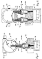
- the gate member 18 is shiftable between a valve open position (Fig. 3) wherein the aperture 52 is in registry with the passageway 14, and a valve closed position (Fig. 4), wherein the gate member 18 is shifted downwardly within passageway 28 so that the aperture 52 is fully out of register with passageway 14, thus blocking flow therethrough.
- the actuator 20 includes an upright, tubular piston cylinder 56 having a base 58 having a vertical through-bore 59, as well as an annular top fixture 60.
- the base 58 is secured to plate 36 via screws 62, whereas the top fixture 60, surmounting the upper end of cylinder 56, is attached to the base 58 by means of long shank connectors 64.
- the base 58 is equipped with a pair of conventional, threadably secured venting mufflers 66 which communicate with through-bore 59.
- the top fixture 60 has threaded bore 68 designed to receive the cartridge unit 22 as will be described.
- the cylinder 56, base 58 and top fixture 60 cooperatively define an internal piston chamber 70.
- An elongated piston rod 71 is secured to the upper end of gate member 18 and extends through the bore 59 into chamber 70.
- a circular piston 72 is secured to the uppermost end of rod 71 as shown, and is slidable within the chamber 70.
- the gas-generating cartridge or unit 22 is threadably received within bore 68 of fitting 60, and is illustrated in detail in Fig. 2.
- the cartridge unit 22 has a tubular outlet section 74 which is externally threaded for receipt within the bore 68 and has internal threading 75 as well, an annular, threaded transition piece 76, an intermediate, annular body part 78, and a rearmost terminal part 80.
- the transition piece 76 is threadably coupled to the rearward end of section 74 and presents a shoulder 82; the forward end of body part 78 has a complemental shoulder 84 abutting the shoulder 82.
- a threaded annular clamp 86 is employed to clamp the body part 78 against transition piece 76.
- the rearward end of intermediate part 78 is threaded as shown, and receives the forward end of terminal part 80.
- a tubular propellant body 90 having an elongated, externally threaded extension 92 is received within chamber 88 and is coupled to threading 75 of outlet section 74.
- the body contains solid propellant 94 preferably in the form of granules of smokeless powder.
- the powder is a conventional formulation comprising a mixture of potassium perchlorate, nitroglycerin, nitrocellulose and lead thiocyanate having minimum auto-ignition temperature of about 163°C (325°F) and a DOT classification of 1.4s and a UN classification of 0323.
- the smokeless powder should be adequate to generate gaseous products of combustion to operate the valve assembly 10 as described below.
- the forward end of the extension 92 is fitted with a consumable closure disc 96; the disc 96 preferably comprises a thin circular plastic or resin element which protects the smokeless powder charge from exposure to the atmosphere during distribution and storage of the cartridge unit 22.
- An ignition disc 98 is positioned within the body 90 in contact with the propellant 94.
- the disc is preferably made up of an ignition composition comprising primarily potassium perchlorate.
- Two pairs of electrical ignition leads 100, 102 are operably coupled with the disc 98 and extend rearwardly out of the cartridge body as shown.
- a tubular lead guide 104, having an internal liner 106, is threaded into the rearward end of body 90. Each such pair comprises two metallic bridge wire elements in contact with the rearward face of the disc 98.
- This preferred embodiment is a design for a retrofit. Alternatively, a design for a new installation may differ slightly.
- a dampener unit broadly designated 99 is supported by bottom plate 38 in direct alignment with the slidable gate member 18 and in disposition to be engaged directly by the lower edge of the gate member.
- the dampener unit embodiment illustrated in Fig. 1 and shown in greater detail in Figs. 11 and 12, comprises a honeycomb cellular element 101 having a number of hexagonal cells 103 arranged with the longitudinal axes thereof extending in parallel relationship to the path of sliding movement of the gate member 18.
- the cells 103 are formed of 0.254 mm (0.010 in.) thick 304 stainless steel, with the flat-to-opposed flat dimension of the individual cells being approximately 3.2 mm (1/8 in.).
- the height and width of the cellular element 101 is preferably about 25.4 mm x 25.4 mm (1" x 1"), with length thereof being dependent upon the transverse width of the gate member 18 of a specific size of gate valve apparatus.
- the dampener unit 99 is preferably used in gate valve apparatus for piping having a diameter of 254 mm (10 in.) or greater.
- An alternative dampener unit 299 is illustrated in Fig. 10 of the drawings, and comprises an elastomeric element 301 comprising a strip of elastomer that is desirably about 25.4 mm x 25.4 mm (1" x 1") in height and width, and also of a length approximately equal to the transverse dimension of the gate member 18 of a particular gate valve apparatus.
- a preferred element 301 is of neoprene having a Shore A hardness of about 60 to about 70.
- valve assembly 10 the gate member 18 is normally in the valve open position shown in Fig. 3 where the valve member is in its elevated position with aperture 52 thereof in registry with passageway 14, and with piston 72 in its uppermost position slightly below the top fixture 60. In such orientation, the seals 48, 50 prevent passage of fluid into the chamber 28 of the valve.
- a sensor not shown
- an appropriate current is introduced into the ignition leads 100, 102 so as to actuate the disc 98. This causes rapid ignition of the propellant 94, resulting in generation of hot products of combustion. This serves to initially generate pressure within fitting 60 above piston 72. Consequently, the piston 72 is driven rapidly downwardly within the cylinder 56 as viewed in Fig. 4 and the plate member 15 is likewise shifted downwardly until the aperture 52 is fully out of communication with passageway 14, thereby closing the latter and preventing any additional fluid flow therethrough.
- the cartridge or unit 22 has a gas generating propellant in which the formulation, burn rate, and quantity are correlated to produce a sufficient volume of subsonic gas at a velocity which causes the gate valve 18 to be shifted toward its closed position at a velocity of from about 5.1 meters per second (0.2 in./msec) to about 8.4 meters per second (0.33 in./ms).
- the propellant charge is of characteristics such that the velocity profile for each size of gate valve during shifting meets the criteria of moving from its fully opened position to its fully closed position in about 3 to about 5 msec for each 25.4 mm (inch) of pipe diameter in which the gate valve assembly is to be mounted.
- the closing time of the gate valve member 18 should be no slower than about 50 msec, and no faster than about 30 msec.
- Controlled acceleration of the gate valve member 18 during opening thereof prevents the gate valve member from impacting against components of the housing thereof with sufficient force to cause damage to the components, and from bouncing to an extent that the valve aperture 14 could reopen. Avoidance of reopening of the valve member 18 is especially important in those instances where the gate valve apparatus of this invention is used in an explosion isolation system. If the piping in which the gate valve apparatus is mounted leads to an area where an explosion can occur, adverse events that must be avoided include failure of the valve to close rapidly enough to prevent a flame front or deflagration products from advancing through the valve before closure thereof takes place, and reopening of the valve to any extent that would permit the flame or deflagration products from escaping through the valve that should otherwise be fully closed.
- the dampener unit 99 or 299 in a particular size of gate valve apparatus contributes to avoidance of deleterious impact forces being imparted to the housing of the gate valve apparatus when the gate valve member 18 reaches its fully closed position.
- Engagement of the gate valve with the dampener unit 99 or 299 decelerates shifting of the gate valve member in a predetermined, controlled manner thus preventing transfer of damaging impact forces to the housing from the gate valve member 18 during closure, and at the same time precluding bouncing of the gate valve element to an extent that the aperture 14 could reopen.
- dampener unit 299 In the case of elastomeric dampener unit 299, the characteristics of that unit are such that deceleration of the gate member 18 is fully and rapidly accomplished, but the unit 299 is not so elastic that it tends to cause the gate valve member 18 to bounce, either once or repeatedly, and thus move away from its full closed position.
- the preferred neoprene material used in fabricating dampener unit 299 has a Shore A hardness of about 60 to about 70, which has been found to provide smooth and essentially bounce-free dampening of the gate valve member 18 as it is shifted toward its closed position.
- Gate valve apparatus or assemblies 10 designed for use in piping having a diameter of 254 mm (10 in.) or greater preferably employ the honeycomb cellular structure 101 illustrated in Figs. 1, 11 and 12, wherein the structure 101 is oriented such that the axes of the individual cells 103 are parallel to the path of travel of the gate valve member 18 as it closes. Engagement of the gate valve member 18 with the adjacent face of the honeycomb structure causes the cells to progressively collapse in a controlled manner, thus providing controlled and progressive deceleration of the gate valve member 18.
- Fig. 5 illustrates a modified valve assembly 10a which is identical with assembly 10, except that the top fitting 60a is designed to receive and position the cartridge unit 22a in an upright orientation in substantial axial alignment with piston rod 71a and the underlying valve gate member (not shown).
- the fitting 60a includes a lower most threaded plug section 104 surmounting the cylinder 56a.
- the plug 104 has an internally threaded bore 106 receiving the threaded extension 92a of the cartridge unit 22a.
- a metallic, cup-like cover 108 is secured to the section 104 and has small openings 110 through the upper wall thereof for passage of the ignition leads 100a, 102a.
- the operation of the assembly 10a is in all respects identical with that described with reference to valve assembly 10.
- Fig. 6 illustrates yet another embodiment in the form of valve assembly 10b.
- a tubular top fitting 112 is operatively attached to the upper end of the housing 56b.
- a yoke coupler 114 having an externally threaded tubular mounting section 116 is received within the threaded bore 118 of the fitting 112.
- the coupler 114 includes a pair of diverging tubular arms 120, 122 which are each the equivalent of the outlet section 74 described previously.
- the remaining components of the cartridge body are operatively secured to each of the arms 120, 122, namely the transition piece 76b, the intermediate piece 78b and terminal part 80b, forming respective propellant-receiving chambers 88b.
- Identical propellant bodies 90b are located within each of the chambers 88b, with the extensions 92b thereof threadably received within the bores of the legs 120, 122.
- the propellant charges within each of the bodies 90b are simultaneously ignited, thereby causing gaseous products of combustion from both of these charges to pass downwardly through yoke coupler 114b so as to drive the piston 72b downwardly within the housing 56b. This of course moves the associated gate member as described.
- Fig. 7 depicts another embodiment 124 of the invention which is similar in many respects to that illustrated in Fig. 1. That is, the valve 124 includes a valve body 126 and gate unit 128 identical to the valve body 12 and gate unit 16 previously described. In this case, the actuator 130 is very similar to the actuator 20, but is oriented in axial alignment with the gate valve 128. In addition, the actuator 128 is equipped with an outboard, threaded adapter 132 received within a correspondingly threaded boss 134. An elongated, tubular, threaded extension 136 is received within the adapter 132 as shown, and supports a hollow metallic housing 138, the latter having tubular end fittings 140, 142.
- the ignition wires 144 associated with the actuator 130 extend through the adapter 132 and extension 136 into the confines of housing 138. These wires then extend through the fittings 140, 142 for appropriate connection to a sensor and power source as required.
- the remaining structure of the actuator 130, and the overall valve 124 are identical with the corresponding structure of Fig. 1, and the operation of the valve is essentially identical as well.
- the provision of the housing 138 and its associated support structure adds a measure of safety to the operation of the valve, by encasing the ignition wires 144 so as to prevent environmental contamination and/or degradation thereof.
- Fig. 8 illustrates a valve 146 which is identical with valve 126 of Fig.
- a pair of juxtaposed actuators 130 are employed in lieu of the single actuator of Fig. 7.
- the bosses 134, adapters 132 and extensions 136 in order to support a appropriately sized housing 148 which receives the ignition wire sets 144 from each of the actuators 130.
- the housing 148 has tubular end fittings 150, 152 so that the ignition wires may be connected as indicated previously.
- the valve 140 corresponds to the valve 126.
- a preferred form of the gate valve assembly as shown in Figs. 9 and 10 is designated by the numeral 210.
- the valve assembly 210 has many components which are the same or similar to elements of valve assembly 10 as depicted in Figs. 1 and 5.
- the gate valve 212 has components which are the same, function the same, and operate the same as the components of valve body 12 previously described in connection with valve assembly 10 Figs. 1-4.
- An actuator 220 includes a tubular housing made up of a cylinder 256 which houses a reciprocable piston 272 attached to a piston rod 271 that is connected directly to the plate 224 that serves as the gate valve.
- Plate 224 has a circular opening 214 therein of the same diameter as the aligned passages 228 and 229 in flanges 242 and 244, respectively, of the gate valve 212.
- the actuator 216 has a top fixture 260 connected directly to the upper circular edge of cylinder 256.
- Fixture 260 has an irregularly configured passage 262 therethrough communicating with the interior of cylinder 256 and which mounts a gas cartridge actuator unit 222 that is of the same construction as cartridge unit 22 previously described.
- the propellant formulation of cartridge unit 222 is a combination of potassium perchlorate, nitroglycerin, nitrocellulose and lead thiocyanate, as previously described and has the same properties and specification referred to with respect to cartridge unit 22.
- the proportion of constituents of the propellant formulation, the quantities thereof, and the burn rate are correlated such that upon burning of the propellant, when the hot products of combustion of the propellant burning are directed into a test vessel having a volume of 32 cc's, a measured pressure of from 310 barg (4,500 psig) to about 372 barg (5,400 psig) results. Furthermore, the composition of the propellant and the rate of burn of that propellant are coordinated such that the flow rate of products of combustion directed into housing 256 from the cartridge unit upon ignition of the propellant remains subsonic and therefore does not exceed 331 meters per second (mach 1).
- a suitable gas cartridge actuator is supplied by Fike Corporation, Blue Springs, Missouri, as part No. 02-4134.
- piston 272 in its initial location in closest proximity to the fixture 260 is in direct facing relationship to the discharge end 263 of cartridge unit 222. Furthermore, the face 272a of piston 272 which faces fixture 260, and the surface 260a of fixture 260 cooperate to define a pressurized gas-receiving, expandable chamber 280.
- a housing 282 for electrical control components is mounted on the outer end of the cartridge unit 222 which preferably contains an electrical release module that is electrically connected to the initiator forming a part of the unit 222.
- an electrical signal is received for triggering of the gate valve to either open or close the passage therethrough, the electrical resistance initiator wires are caused to conduct electrical current, thus creating sufficient heat to ignite the initiator charge which in turn ignites the propellant mixture in the cartridge unit.
- the piston and cylinder assembly made up of tubular housing 256 and piston 272 preferably employ a piston having a diameter of 76.2 mm (3 inches) for use in piping having a diameter of 50.8 mm (2 inches), 76.2 mm (3 inches), 101.6 mm (4 inches), 152.4 mm (6 inches), 203.2 mm (8 inches), and 254 mm (10 inches), while isolation valves for use in piping systems in which the pipes have a diameter 304.8 mm (12 inches), 355.6 mm (14 inches), 406.4 mm (16 inches), 457.2 mm (18 inches), 508 mm (20 inches), and 609.6 mm (24 inches), for example, desirably employ a piston and enclosing housing wherein the piston has a diameter of 101.6 mm (4 inches).
- gate valve apparatus for use in respective equivalent diameter piping in metric dimensions.
- the gate valve apparatus is constructed and dimensioned such that the gate valve 24 or 224 is shifted through a displacement adequate to effect opening or closing of the orifice in the pipeline as the case may be.
- the valve plate in the instance of a 50.8 mm (2 in.) valve, the valve plate must moved through a displacement of at least 50.8 mm (2 ins.), while the valve plate must be moved through a displacement of at least 609.6 mm (24 ins). for a 609.6 mm (24 in). pipe. Proportional displacement of the valve plate is required for other pipe sizes.
- each gate valve apparatus of this invention regardless of its size depending upon the diameter of the piping in which the gate valve apparatus is to be used, is constructed such that there is space between the face of the piston and the adjacent gas discharge end of the cartridge 22 or 222.
- This spacing which at a minimum should be at least about 6.35 mm (1/4 in.) in the embodiment of the invention illustrated in Fig. 10, ensures that the gas discharged from the outlet orifice of the gas producing cartridge 22 or 222 spreads uniformly over the adjacent face of the piston to thereby initiate movement of the piston and consequent shifting of the gate valve member or plate 18 or 224.
- the space that is provided between the face of the piston 72 or 272 and an associated cartridge 22 or 222 serves to modulate the pressurized gas exiting from the gas generating cartridge against the adjacent face of the piston and thereby prevent untoward initial forces being imposed on the piston immediately after actuation of the cartridge. It has been found that by varying the volume of that space between the cartridge and the piston depending upon the size of the gate valve apparatus, required control over acceleration of the piston and the gate valve member connected thereto can be closely and advantageously controlled to assure that the speed of operation is maintained within the required parameters as noted above.
- initial space beyond the minimum 6.35 mm (1/4 in.) space between the piston and gas cartridge has been found to be adequate in gas cartridge actuated isolation valve apparatus sized for 76.2 mm (3 in.), 101.6 mm (4 in.), 152.4 mm (6 in.) and 203.2 mm (8 in.) piping.
- the minimum 1/4 in. initial space between the piston and the gas cartridge in the initial position of the piston has proved to be sufficient for gas cartridge actuated valve apparatus sized to be used in 254 mm (10 in.), 304.8 mm (12 in.), 355.6 mm (14 in.) and 406.4 mm (16 in.) valves.
- An additional approximately 50.8 mm (2 in.). initial space has been determined to be adequate for valve apparatus for 508 mm (20 in.) piping.
- the propellant charge should preferably be formulated to produce gaseous products of combustion directed into a 76.2 mm (3 inch) diameter actuator 220 that cause the gate valve plate 224 to move to its fully actuated position in a time interval of about 18 msec, with the pressure relatively uniformly declining during that time from a pressure of about 41.4 barg (600 psig) to about 0 barg (0).
Landscapes
- Engineering & Computer Science (AREA)
- General Engineering & Computer Science (AREA)
- Mechanical Engineering (AREA)
- Sliding Valves (AREA)
- Filling Or Discharging Of Gas Storage Vessels (AREA)
- Feeding And Controlling Fuel (AREA)
- Safety Valves (AREA)
Claims (9)
- Absperrschieberanordnung (10) mit einem Schieberkörper (12), durch den ein Durchgang (14) vorgesehen ist, einer Schiebereinheit (16), die ein verschiebbares Schieberelement (18) enthält, das in der Nähe des Durchgangs vorgesehen ist und zwischen einer Position, in der der Schieber geöffnet ist und die einen Durchfluß durch den Durchgang (14) zuläßt, und einer Position verschiebbar ist, in der der Schieber geschlossen ist und in der sich das Schieberelement (18) in einer durchflußblockierenden Ausrichtung in Bezug auf den Durchgang (14) befindet, und einem Betätigungselement (20) zum Verschieben des Schieberelements (18) zwischen den Positionen, wobei das Betätigungselement ein längliches rohrförmiges Gehäuse (56), einen in Längsrichtung des Gehäuses verschiebbaren Kolben (72) und eine mit dem Kolben und dem Schieberelement verbundene Kolbenstange (71) zum Verschieben des Schieberelements zwischen der Position, in der der Schieber geöffnet ist, und der Position, in der der Schieber geschlossen ist, in Abhängigkeit von einer Bewegung des Kolbens aufweist, wobei das Betätigungselement aufweist:eine gaserzeugende Patroneneinheit (22) mit einem Gasabgabeende,wobei die Patroneneinheit (22) mit dem rohrförmigen Gehäuse (56) in einer Anordnung verbunden ist, die eine ausdehnbare, unter Druck stehendes Gas aufnehmende Kammer (70) zwischen dem Kolben (72) und dem Gasabgabeende der Patrone bildet,wobei die Patroneneinheit (22) mit einer entzündbaren gaserzeugenden Ladung (94) versehen ist, die bei einer Zündung mit einer kontrollierten Geschwindigkeit brennt und einen Fluß unter Druck stehender gasförmiger Verbrennungsprodukte erzeugt, die in die Kammer mit einer Geschwindigkeit strömen, die eine Geschwindigkeit von 331 Meter pro Sekunde (Mach 1) nicht überschreitet,wobei der Kolben (72) zur Bewegung aus einer anfänglichen Position benachbart zu, aber beabstandet von dem Abgabeende der Patroneneinheit (22) in eine betätigte Position durch unter Druck stehendes Gas angeordnet ist, das von der gaserzeugenden Patroneneinheit (22) in die Kammer (70) geleitet wird, um das Verschieben des Schieberelements (18) aus einer Position von ihm in die andere Position desselben zu bewirken,wobei der Kolben (72) in seiner anfänglichen Position in einem Abstand von dem Abgabeende der Patrone angeordnet ist, der ausreicht, um zu verhindern, daß unter Druck stehendes Gas, das bei der Zündung der Ladung zuerst in die Kammer eintritt, beschädigende Schockkräfte auf den Kolben, die mit diesem verbundene Stange (71) oder den Schieber überträgt,wobei die gaserzeugende Ladung den Kolben (72) und auf diese Weise das Schieberelement (18) aus der anfänglichen Position des Kolbens in seine betätigte Position mit einer Geschwindigkeit von 5,1 Meter pro Sekunde (0,2 Inch/msek) bis 8,4 Meter pro Sekunde (0,33 Inch/msek) verschiebt.
- Anordnung nach Anspruch 1, bei der eine Dämpfungseinheit (99) vorgesehen ist, die so angeordnet ist, daß das Schieberelement (18) an ihr angreift, wenn sich der Kolben (72) seiner betätigten Position nähert, um eine kontrollierte, vorbestimmte Abbremsung des Schieberelements (18) zu bewirken.
- Anordnung nach Anspruch 2, bei der die Dämpfungseinheit (99) ein elastomeres Element mit einer Shore A-Härte von ungefähr 60 bis ungefähr 70 ist.
- Anordnung nach Anspruch 2, bei der die Dämpfungseinheit (99) ein wabenartiges, zellenförmiges Element (101) ist, das in einer Anordnung ausgerichtet ist, in der die Achsen seiner Zellen in einer im wesentlichen parallelen Beziehung zu der Bewegungsbahn des Schieberelements sind, was bewirkt, daß das zellenförmige Element zerdrückt wird und das Schieberelement abbremst, wenn es sich in seine betätigte Position bewegt.
- Anordnung nach Anspruch 1, bei der die Patroneneinheit (22) einen länglichen Patronenkörper (90) aufweist, der in einer quer verlaufenden Beziehung zu dem Gehäuse (56) ausgerichtet ist.
- Anordnung nach Anspruch 1, bei der die Patroneneinheit (22) einen länglichen Patronenkörper (90) aufweist, der im wesentlichen fluchtend mit dem Gehäuse (56) ausgerichtet ist.
- Anordnung nach Anspruch 1, bei der eine Vielzahl der gaserzeugenden Patroneneinheiten (22) vorgesehen ist, von denen sich alle in unmittelbarer, zugewandter Verbindung mit der Kammer befinden.
- Anordnung nach Anspruch 1, bei der eine Steuervorrichtung (282) für die Patroneneinheit (22) vorgesehen ist,
wobei die Steuervorrichtung an dem rohrförmigen Gehäuse (56) in unmittelbarer Zuordnung zu der Patroneneinheit montiert ist. - Verfahren zum wahlweisen Betätigen einer Absperrschieberanordnung mit einem Schieberkörper (12), durch den ein Durchgang (14) vorgesehen ist, einer Schiebereinheit (16), die ein verschiebbares Schieberelement (18) enthält, das in der Nähe des Durchgangs vorgesehen ist und zwischen einer Position, in der der Schieber geöffnet ist und die einen Durchfluß durch den Durchgang (14) zuläßt, und einer Position verschiebbar ist, in der der Schieber geschlossen ist und in der sich das Schieberelement (18) in einer durchflußblockierenden Ausrichtung in Bezug auf den Durchgang (14) befindet, und einem verbesserten Betätigungselement (20) zum Verschieben des Schieberelements (18) zwischen den Positionen, wobei das Verfahren die folgenden Schritte aufweist:Erzeugen einer Ladung unter Druck stehenden Gases, das eine Geschwindigkeit hat, die ungefähr 331 Meter pro Sekunde (Mach 1) nicht überschreitet, undVeranlassen, daß die Ladung unter Druck stehenden Gases eine Verschiebung des Schieberelements mit einer Geschwindigkeit von 5,1 Meter pro Sekunde (0,2 Inch/msek) bis 8,4 Meter pro Sekunde (0,33 Inch/msek) bewirkt.
Applications Claiming Priority (5)
| Application Number | Priority Date | Filing Date | Title |
|---|---|---|---|
| US13357398A | 1998-08-13 | 1998-08-13 | |
| US133573 | 1998-08-13 | ||
| US373087 | 1999-08-12 | ||
| PCT/US1999/018478 WO2000009920A1 (en) | 1998-08-13 | 1999-08-12 | Gas cartridge actuated isolation valve |
| US09/373,087 US6131594A (en) | 1998-08-13 | 1999-08-12 | Gas cartridge actuated isolation valve |
Publications (3)
| Publication Number | Publication Date |
|---|---|
| EP1104522A1 EP1104522A1 (de) | 2001-06-06 |
| EP1104522A4 EP1104522A4 (de) | 2004-03-24 |
| EP1104522B1 true EP1104522B1 (de) | 2006-05-24 |
Family
ID=26831483
Family Applications (1)
| Application Number | Title | Priority Date | Filing Date |
|---|---|---|---|
| EP99945059A Expired - Lifetime EP1104522B1 (de) | 1998-08-13 | 1999-08-12 | Ventil betätigt über gasdruckbehälter |
Country Status (6)
| Country | Link |
|---|---|
| US (1) | US6131594A (de) |
| EP (1) | EP1104522B1 (de) |
| CN (1) | CN1312900A (de) |
| AT (1) | ATE327460T1 (de) |
| BR (1) | BR9913639A (de) |
| DE (1) | DE69931499T2 (de) |
Families Citing this family (18)
| Publication number | Priority date | Publication date | Assignee | Title |
|---|---|---|---|---|
| US8282074B2 (en) * | 2001-03-12 | 2012-10-09 | Curtiss-Wright Flow Control Corporation | Delayed coker isolation valve systems |
| US8123197B2 (en) * | 2001-03-12 | 2012-02-28 | Curtiss-Wright Flow Control Corporation | Ethylene production isolation valve systems |
| DE20115467U1 (de) * | 2001-09-20 | 2003-02-20 | CAMERON GmbH, 29227 Celle | Absperrvorrichtung |
| CN100398903C (zh) * | 2006-06-08 | 2008-07-02 | 西安理工大学 | 一种可远程遥控的大阀门系统 |
| US8851451B2 (en) * | 2009-03-23 | 2014-10-07 | Curtiss-Wright Flow Control Corporation | Non-rising electric actuated valve operator |
| US8397741B2 (en) * | 2009-06-10 | 2013-03-19 | Baker Hughes Incorporated | Delay activated valve and method |
| DE102010033438B4 (de) * | 2010-08-04 | 2013-10-31 | Dominic Becker | Absperrarmatur |
| CN102829232B (zh) * | 2011-06-14 | 2016-02-24 | Tlx技术有限公司 | 用于助力致动器的螺线管联锁装置 |
| US8640783B2 (en) | 2011-06-14 | 2014-02-04 | Tlx Technologies, Llc | Solenoid interlock for booster actuator |
| US9512927B2 (en) | 2012-02-29 | 2016-12-06 | Fike Corporation | Pneumatic gate valve with integrated pressurized gas reservoir |
| CN102691817B (zh) * | 2012-05-28 | 2013-09-18 | 中船重工特种设备有限责任公司 | 一种高精度高可靠性安全阀门 |
| CN102927341B (zh) * | 2012-11-16 | 2014-12-17 | 上海宇航系统工程研究所 | 一种楔入防回弹电爆阀 |
| CN103968121A (zh) * | 2013-02-01 | 2014-08-06 | 中核苏阀科技实业股份有限公司 | 一种双盲管结构的快开阀 |
| RU2675945C2 (ru) * | 2014-02-28 | 2018-12-25 | Файк Корпорейшн | Пассивный взрывозащитный клапан с импульсной струйной очисткой |
| EP2949975B1 (de) | 2014-05-22 | 2017-03-29 | Rico-Sicherheitstechnik AG | Explosionsschutzschieber zum Unterbrechen eines Fluidstroms in einer Rohrleitung |
| CN105422958B (zh) * | 2014-09-22 | 2018-02-13 | 天津市塘沽津滨阀门有限公司 | 一种全自动闸板式避险装置 |
| WO2019195200A1 (en) * | 2018-04-03 | 2019-10-10 | Kinetic Pressure Control, Ltd. | Kinetic shear ram for well pressure control apparatus |
| WO2020172112A1 (en) | 2019-02-19 | 2020-08-27 | Fike Corporation | Passive explosion isolation valve with vertically oriented flaps |
Family Cites Families (15)
| Publication number | Priority date | Publication date | Assignee | Title |
|---|---|---|---|---|
| US3358961A (en) * | 1963-03-05 | 1967-12-19 | Rayner A Montgomery | Explosively driven shutter type pressure release apparatus |
| US3494370A (en) * | 1964-06-22 | 1970-02-10 | Wahl Corp William | Explosive valve |
| US3373758A (en) * | 1965-09-27 | 1968-03-19 | Gen Motors Corp | High speed gate valve |
| US3720620A (en) * | 1970-07-20 | 1973-03-13 | D Taber | Synergistic antiseptic compositions |
| US3739796A (en) * | 1971-05-03 | 1973-06-19 | Us Army | In-line explosion arrester |
| US3702620A (en) * | 1971-08-10 | 1972-11-14 | Atomic Energy Commission | Actuator system |
| US4108195A (en) * | 1977-06-23 | 1978-08-22 | Berry Henry K | Quick-closing fire gate |
| US4290578A (en) * | 1978-09-01 | 1981-09-22 | Earp Sherald B | Failsafe cutoff valve for oil and gas wells |
| US4215749A (en) * | 1979-02-05 | 1980-08-05 | Acf Industries, Incorporated | Gate valve for shearing workover lines to permit shutting in of a well |
| FR2503313B1 (fr) * | 1981-04-03 | 1985-10-18 | Pyromeca Sa | Vanne pyrotechnique d'obturation ultrarapide d'une canalisation |
| FR2561743B1 (fr) * | 1984-03-21 | 1986-09-05 | Aerospatiale | Vanne pyrotechnique |
| US4794890A (en) * | 1987-03-03 | 1989-01-03 | Magnavox Government And Industrial Electronics Company | Electromagnetic valve actuator |
| US5205069A (en) * | 1991-10-02 | 1993-04-27 | The United States Of America As Represented By The United States Department Of Energy | High speed door assembly |
| EP0624743A1 (de) * | 1993-05-10 | 1994-11-17 | Fenwal Safety Systems, Inc. | Hochgeschwindigkeitsabsperrschieber |
| US5853018A (en) * | 1997-02-28 | 1998-12-29 | Eaton Corporation | Dampening resonance in a flow regulator |
-
1999
- 1999-08-12 CN CN99809607A patent/CN1312900A/zh active Pending
- 1999-08-12 EP EP99945059A patent/EP1104522B1/de not_active Expired - Lifetime
- 1999-08-12 AT AT99945059T patent/ATE327460T1/de not_active IP Right Cessation
- 1999-08-12 DE DE69931499T patent/DE69931499T2/de not_active Expired - Lifetime
- 1999-08-12 US US09/373,087 patent/US6131594A/en not_active Expired - Lifetime
- 1999-08-12 BR BR9913639-2A patent/BR9913639A/pt not_active IP Right Cessation
Also Published As
| Publication number | Publication date |
|---|---|
| BR9913639A (pt) | 2001-06-05 |
| DE69931499D1 (de) | 2006-06-29 |
| EP1104522A4 (de) | 2004-03-24 |
| ATE327460T1 (de) | 2006-06-15 |
| DE69931499T2 (de) | 2007-04-26 |
| CN1312900A (zh) | 2001-09-12 |
| EP1104522A1 (de) | 2001-06-06 |
| US6131594A (en) | 2000-10-17 |
Similar Documents
| Publication | Publication Date | Title |
|---|---|---|
| US6131594A (en) | Gas cartridge actuated isolation valve | |
| US5992528A (en) | Inflator based fire suppression system | |
| TWI803607B (zh) | 用於產生高振幅壓力波的裝置和方法 | |
| EP1558492B1 (de) | Türbetätigungssystem für notfälle | |
| US4308721A (en) | Fluid supply systems | |
| EP1011815B1 (de) | Feuerlöscher mit elektrischer steuerung | |
| CA2222584A1 (en) | Assembly for deaccelerating a driver in a tool | |
| WO2002067743A1 (en) | Deflagration and explosion suppression and isolation apparatus for contained hazardous material | |
| MX2014010251A (es) | Valvula de compuerta neumatica con deposito de gas presurizado integrado. | |
| US6010112A (en) | Driving device for a shut-off device in a pipe-line | |
| US5052494A (en) | Explosion suppression device | |
| CA2340395C (en) | Gas cartridge actuated isolation valve | |
| US7726124B2 (en) | Blast simulator with high velocity actuator | |
| JP7034075B2 (ja) | アクチュエータ | |
| MXPA01001572A (en) | Gas cartridge actuated isolation valve | |
| US3985058A (en) | Self-sealing fluidic explosive initiator | |
| US4244386A (en) | Valve having pyrotechnic separation device | |
| EP2019909B1 (de) | Verfahren und vorrichtung für ein aktuatorsystem | |
| EP1419318B1 (de) | Autonomer gasangetriebener zylinder | |
| EP3646362A1 (de) | Aktuator | |
| EP0676610A1 (de) | Freikolbenmaschine | |
| US20200063643A1 (en) | Combustion chamber valve and fuel system for driven fastener hand tool | |
| JPH02500932A (ja) | 水中爆雷ヒューズ | |
| US3130547A (en) | Fluid control device | |
| RU2046201C1 (ru) | Пиропереключатель |
Legal Events
| Date | Code | Title | Description |
|---|---|---|---|
| PUAI | Public reference made under article 153(3) epc to a published international application that has entered the european phase |
Free format text: ORIGINAL CODE: 0009012 |
|
| 17P | Request for examination filed |
Effective date: 20010309 |
|
| AK | Designated contracting states |
Kind code of ref document: A1 Designated state(s): AT BE CH CY DE DK ES FI FR GB GR IE IT LI LU MC NL PT SE |
|
| AX | Request for extension of the european patent |
Free format text: AL;LT;LV;MK;RO;SI |
|
| A4 | Supplementary search report drawn up and despatched |
Effective date: 20040206 |
|
| RIC1 | Information provided on ipc code assigned before grant |
Ipc: 7F 16K 3/02 B Ipc: 7F 16K 17/40 A |
|
| 17Q | First examination report despatched |
Effective date: 20050401 |
|
| GRAP | Despatch of communication of intention to grant a patent |
Free format text: ORIGINAL CODE: EPIDOSNIGR1 |
|
| GRAS | Grant fee paid |
Free format text: ORIGINAL CODE: EPIDOSNIGR3 |
|
| GRAA | (expected) grant |
Free format text: ORIGINAL CODE: 0009210 |
|
| AK | Designated contracting states |
Kind code of ref document: B1 Designated state(s): AT BE CH CY DE DK ES FI FR GB GR IE IT LI LU MC NL PT SE |
|
| PG25 | Lapsed in a contracting state [announced via postgrant information from national office to epo] |
Ref country code: NL Free format text: LAPSE BECAUSE OF FAILURE TO SUBMIT A TRANSLATION OF THE DESCRIPTION OR TO PAY THE FEE WITHIN THE PRESCRIBED TIME-LIMIT Effective date: 20060524 Ref country code: IT Free format text: LAPSE BECAUSE OF FAILURE TO SUBMIT A TRANSLATION OF THE DESCRIPTION OR TO PAY THE FEE WITHIN THE PRESCRIBED TIME-LIMIT;WARNING: LAPSES OF ITALIAN PATENTS WITH EFFECTIVE DATE BEFORE 2007 MAY HAVE OCCURRED AT ANY TIME BEFORE 2007. THE CORRECT EFFECTIVE DATE MAY BE DIFFERENT FROM THE ONE RECORDED. Effective date: 20060524 Ref country code: FI Free format text: LAPSE BECAUSE OF FAILURE TO SUBMIT A TRANSLATION OF THE DESCRIPTION OR TO PAY THE FEE WITHIN THE PRESCRIBED TIME-LIMIT Effective date: 20060524 Ref country code: AT Free format text: LAPSE BECAUSE OF FAILURE TO SUBMIT A TRANSLATION OF THE DESCRIPTION OR TO PAY THE FEE WITHIN THE PRESCRIBED TIME-LIMIT Effective date: 20060524 |
|
| REG | Reference to a national code |
Ref country code: GB Ref legal event code: FG4D |
|
| REG | Reference to a national code |
Ref country code: CH Ref legal event code: EP |
|
| REG | Reference to a national code |
Ref country code: IE Ref legal event code: FG4D |
|
| REF | Corresponds to: |
Ref document number: 69931499 Country of ref document: DE Date of ref document: 20060629 Kind code of ref document: P |
|
| PG25 | Lapsed in a contracting state [announced via postgrant information from national office to epo] |
Ref country code: IE Free format text: LAPSE BECAUSE OF NON-PAYMENT OF DUE FEES Effective date: 20060814 |
|
| REG | Reference to a national code |
Ref country code: CH Ref legal event code: NV Representative=s name: R. A. EGLI & CO. PATENTANWAELTE |
|
| PG25 | Lapsed in a contracting state [announced via postgrant information from national office to epo] |
Ref country code: SE Free format text: LAPSE BECAUSE OF FAILURE TO SUBMIT A TRANSLATION OF THE DESCRIPTION OR TO PAY THE FEE WITHIN THE PRESCRIBED TIME-LIMIT Effective date: 20060824 Ref country code: DK Free format text: LAPSE BECAUSE OF FAILURE TO SUBMIT A TRANSLATION OF THE DESCRIPTION OR TO PAY THE FEE WITHIN THE PRESCRIBED TIME-LIMIT Effective date: 20060824 |
|
| PG25 | Lapsed in a contracting state [announced via postgrant information from national office to epo] |
Ref country code: MC Free format text: LAPSE BECAUSE OF NON-PAYMENT OF DUE FEES Effective date: 20060831 |
|
| PG25 | Lapsed in a contracting state [announced via postgrant information from national office to epo] |
Ref country code: ES Free format text: LAPSE BECAUSE OF FAILURE TO SUBMIT A TRANSLATION OF THE DESCRIPTION OR TO PAY THE FEE WITHIN THE PRESCRIBED TIME-LIMIT Effective date: 20060904 |
|
| PG25 | Lapsed in a contracting state [announced via postgrant information from national office to epo] |
Ref country code: PT Free format text: LAPSE BECAUSE OF FAILURE TO SUBMIT A TRANSLATION OF THE DESCRIPTION OR TO PAY THE FEE WITHIN THE PRESCRIBED TIME-LIMIT Effective date: 20061024 |
|
| NLV1 | Nl: lapsed or annulled due to failure to fulfill the requirements of art. 29p and 29m of the patents act | ||
| ET | Fr: translation filed | ||
| PLBE | No opposition filed within time limit |
Free format text: ORIGINAL CODE: 0009261 |
|
| STAA | Information on the status of an ep patent application or granted ep patent |
Free format text: STATUS: NO OPPOSITION FILED WITHIN TIME LIMIT |
|
| 26N | No opposition filed |
Effective date: 20070227 |
|
| PG25 | Lapsed in a contracting state [announced via postgrant information from national office to epo] |
Ref country code: GR Free format text: LAPSE BECAUSE OF FAILURE TO SUBMIT A TRANSLATION OF THE DESCRIPTION OR TO PAY THE FEE WITHIN THE PRESCRIBED TIME-LIMIT Effective date: 20060825 |
|
| PG25 | Lapsed in a contracting state [announced via postgrant information from national office to epo] |
Ref country code: LU Free format text: LAPSE BECAUSE OF NON-PAYMENT OF DUE FEES Effective date: 20060812 |
|
| PG25 | Lapsed in a contracting state [announced via postgrant information from national office to epo] |
Ref country code: CY Free format text: LAPSE BECAUSE OF FAILURE TO SUBMIT A TRANSLATION OF THE DESCRIPTION OR TO PAY THE FEE WITHIN THE PRESCRIBED TIME-LIMIT Effective date: 20060524 |
|
| PGFP | Annual fee paid to national office [announced via postgrant information from national office to epo] |
Ref country code: DE Payment date: 20130807 Year of fee payment: 15 Ref country code: CH Payment date: 20130813 Year of fee payment: 15 |
|
| PGFP | Annual fee paid to national office [announced via postgrant information from national office to epo] |
Ref country code: GB Payment date: 20130807 Year of fee payment: 15 Ref country code: FR Payment date: 20130808 Year of fee payment: 15 |
|
| PGFP | Annual fee paid to national office [announced via postgrant information from national office to epo] |
Ref country code: BE Payment date: 20130819 Year of fee payment: 15 |
|
| REG | Reference to a national code |
Ref country code: DE Ref legal event code: R119 Ref document number: 69931499 Country of ref document: DE |
|
| REG | Reference to a national code |
Ref country code: CH Ref legal event code: PL |
|
| GBPC | Gb: european patent ceased through non-payment of renewal fee |
Effective date: 20140812 |
|
| PG25 | Lapsed in a contracting state [announced via postgrant information from national office to epo] |
Ref country code: LI Free format text: LAPSE BECAUSE OF NON-PAYMENT OF DUE FEES Effective date: 20140831 Ref country code: BE Free format text: LAPSE BECAUSE OF NON-PAYMENT OF DUE FEES Effective date: 20140831 Ref country code: CH Free format text: LAPSE BECAUSE OF NON-PAYMENT OF DUE FEES Effective date: 20140831 |
|
| REG | Reference to a national code |
Ref country code: FR Ref legal event code: ST Effective date: 20150430 |
|
| REG | Reference to a national code |
Ref country code: DE Ref legal event code: R119 Ref document number: 69931499 Country of ref document: DE Effective date: 20150303 |
|
| PG25 | Lapsed in a contracting state [announced via postgrant information from national office to epo] |
Ref country code: DE Free format text: LAPSE BECAUSE OF NON-PAYMENT OF DUE FEES Effective date: 20150303 Ref country code: GB Free format text: LAPSE BECAUSE OF NON-PAYMENT OF DUE FEES Effective date: 20140812 |
|
| PG25 | Lapsed in a contracting state [announced via postgrant information from national office to epo] |
Ref country code: FR Free format text: LAPSE BECAUSE OF NON-PAYMENT OF DUE FEES Effective date: 20140901 |