EP1104663A2 - Messvorrichtung zur Ermittlung von Augenaberrationen - Google Patents
Messvorrichtung zur Ermittlung von Augenaberrationen Download PDFInfo
- Publication number
- EP1104663A2 EP1104663A2 EP00124288A EP00124288A EP1104663A2 EP 1104663 A2 EP1104663 A2 EP 1104663A2 EP 00124288 A EP00124288 A EP 00124288A EP 00124288 A EP00124288 A EP 00124288A EP 1104663 A2 EP1104663 A2 EP 1104663A2
- Authority
- EP
- European Patent Office
- Prior art keywords
- optical system
- photodetecting
- eye
- light
- illuminating
- Prior art date
- Legal status (The legal status is an assumption and is not a legal conclusion. Google has not performed a legal analysis and makes no representation as to the accuracy of the status listed.)
- Withdrawn
Links
- 230000004075 alteration Effects 0.000 title abstract description 25
- 230000003287 optical effect Effects 0.000 claims abstract description 299
- 230000001131 transforming effect Effects 0.000 claims abstract description 106
- 210000001525 retina Anatomy 0.000 claims abstract description 69
- 238000005259 measurement Methods 0.000 claims description 87
- 230000005494 condensation Effects 0.000 claims 1
- 238000009833 condensation Methods 0.000 claims 1
- 230000002207 retinal effect Effects 0.000 claims 1
- 238000000034 method Methods 0.000 description 75
- 238000013208 measuring procedure Methods 0.000 description 65
- 230000004048 modification Effects 0.000 description 30
- 238000012986 modification Methods 0.000 description 30
- 238000002360 preparation method Methods 0.000 description 29
- 230000007246 mechanism Effects 0.000 description 21
- 206010010071 Coma Diseases 0.000 description 18
- 238000012937 correction Methods 0.000 description 12
- 230000014509 gene expression Effects 0.000 description 12
- 210000001747 pupil Anatomy 0.000 description 8
- 230000004044 response Effects 0.000 description 6
- 201000009310 astigmatism Diseases 0.000 description 4
- 238000010586 diagram Methods 0.000 description 4
- 230000002123 temporal effect Effects 0.000 description 4
- 230000008859 change Effects 0.000 description 3
- 239000002131 composite material Substances 0.000 description 3
- 238000005286 illumination Methods 0.000 description 3
- 101100234408 Danio rerio kif7 gene Proteins 0.000 description 2
- 101100221620 Drosophila melanogaster cos gene Proteins 0.000 description 2
- 101100398237 Xenopus tropicalis kif11 gene Proteins 0.000 description 2
- 238000010276 construction Methods 0.000 description 2
- 210000004087 cornea Anatomy 0.000 description 2
- 238000003780 insertion Methods 0.000 description 2
- 230000037431 insertion Effects 0.000 description 2
- 230000002159 abnormal effect Effects 0.000 description 1
- 101150118300 cos gene Proteins 0.000 description 1
- 230000003247 decreasing effect Effects 0.000 description 1
- 238000009792 diffusion process Methods 0.000 description 1
- 239000004065 semiconductor Substances 0.000 description 1
Images


Classifications
-
- A—HUMAN NECESSITIES
- A61—MEDICAL OR VETERINARY SCIENCE; HYGIENE
- A61B—DIAGNOSIS; SURGERY; IDENTIFICATION
- A61B3/00—Apparatus for testing the eyes; Instruments for examining the eyes
- A61B3/10—Objective types, i.e. instruments for examining the eyes independent of the patients' perceptions or reactions
- A61B3/1015—Objective types, i.e. instruments for examining the eyes independent of the patients' perceptions or reactions for wavefront analysis
-
- G—PHYSICS
- G01—MEASURING; TESTING
- G01J—MEASUREMENT OF INTENSITY, VELOCITY, SPECTRAL CONTENT, POLARISATION, PHASE OR PULSE CHARACTERISTICS OF INFRARED, VISIBLE OR ULTRAVIOLET LIGHT; COLORIMETRY; RADIATION PYROMETRY
- G01J9/00—Measuring optical phase difference; Determining degree of coherence; Measuring optical wavelength
Definitions
- the present invention relates an apparatus for precisely measuring eye characteristics and, more particularly, to an eye characteristic measuring apparatus provided with an image forming condition changing unit for properly adjusting illumination and capable of determining an optimum illuminating condition and an optimum light receiving condition.
- a known measuring apparatus for measuring the optical characteristics of the eye focuses an illuminating optical system on the light receiving level of a first photodetecting device and focuses a photodetecting optical system on the basis of an optical characteristic (S) determined from the output of the first photodetecting device.
- Data provided by the known measuring apparatus for measuring the optical characteristics of the eye can be used only for correcting spectacles, and accordingly it does not have a satisfactory performance.
- an object of the present invention to provide an eye characteristic measuring apparatus capable of providing sufficient data on eye characteristics of the eye.
- an eye characteristic measuring apparatus comprises a first light source that emits light, a first illuminating optical system capable of illuminating a small region of the retina of the eye in a variable illuminating condition, a first photodetecting optical system provided with a first transforming device that divides the reflected light beam into at least seventeen light beams and a first photodetecting device that receives part of reflected light reflected from the retina through the first transforming device, an arithmetic unit that determines the optical characteristics of the eye on the basis of a first signal provided by the first photodetecting device and corresponding to the inclination of the light, and an image forming condition changing unit that changes the respective image forming conditions of the first illuminatipg optical system and the first photodetecting optical system according to the level of the first signal provided by the first photodetecting device.
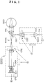
- an eye characteristic measuring apparatus 10000 in a first embodiment according to the present invention includes a first light source 100 that emits light of a first wavelength, a first illuminating optical system 200A capable of illuminating a small region of the retina of the eye 1000 with light emitted by the first light source 100 in various illuminating conditions, a first photodetecting optical system 300A that guides reflected light reflected from the retina of the eye 1000 through a first transforming device 400 that divides the reflected light into at least seventeen light beams to a first photodetecting device 510, an arithmetic unit 600 that determines the optical characteristics of the eye 1000 on the basis of a first signal provided by the first photodetecting device 510 and corresponding to the inclination of the light beam, and an image forming condition changing unit that changes the respective image forming conditions of the first illuminating optical system 200A and the first photodetecting optical system 300A according to the level of the first signal provided by the first photodetecting device 510.
- the arithmetic unit 600 controls all the units and systems including a control unit 610.
- the control unit 610 controls and drives the first light source 100 and such.
- the first light source 100 emits light having a high spatial coherence and a low temporal coherence.
- the first light source 100 of the first embodiment is an SLD, a point source of a high luminance.
- the first light source 100 of the first embodiment does not need necessarily to be an SLD and a laser that emits light having a high spatial coherence and a high temporal coherence may be used in combination with a rotational diffusion plate that lowers the temporal coherence properly.
- An SLD that emits light having a low temporal coherence and a low spatial coherence can be used by placing a screen provided with a pinhole at a position corresponding to the light source, provided that the SLD has a sufficiently high luminous intensity.
- the illuminating light emitted by the first light source 100 may be light of a wavelength in an infrared region, such as 780 nm.
- the first photodetecting device 510 receives both light for optical characteristic measurement and light from the anterior segment of the eye 1000.
- the first illuminating optical system 200A illuminates a small region of the retina of the eye 1000 with the light emitted by the first light source 100.
- the first illuminating optical system 200A includes a first condenser lens 210, a first cylindrical lens 220a and a relay lens 200b.
- the first photodetecting optical system 300A receives the light reflected from the retina of the eye 1000 and guides the same to the first photodetecting device 510.
- the first photodetecting optical system 300A includes a first afocal lens 310, a second cylindrical lens 320a, a second relay lens 320b, a first beam splitter 330 and a transforming device 400 for dividing the reflected light into at least seventeen light beams.
- the first beam splitter 330 of the first photodetecting optical system 300A deflects the light emitted by the first illuminating optical system 200A toward the eye 1000 and transmits the reflected light reflected from the eye 1000.
- the first photodetecting device 510 receives the light through the first receiving optical system 300A and the transforming device 400 and generates a first signal.
- the first light source 100 and the retina of the eye 1000 are conjugate to each other.
- the fundus of the eye 1000 and the first photodetecting device 510 are conjugate to each other.
- the transforming device 400 and the pupil of the eye 1000 are conjugate to each other.
- the front focus of the first afocal lens 310 coincides substantially with the anterior segment of the eye 1000.
- the first illuminating optical system 200A and the first photodetecting optical system 300A are disposed in a positional relation that makes a maximum the peak of the signal generated by the first photodetecting device 510 upon the reception of the light emitted by the first light source 100 and reflected at a point where the light is focused, are coordinated, move in directions to increase the peak of the signal generated by the first photodetecting device 510 and stop at positions where the intensity of the signal is a maximum. In such a state, the light emitted by the first light source 100 is focused on the eye 1000.
- the transforming device 400 will be explained.
- the transforming device 400 included in the first photodetecting optical system 300A is a wavefront transforming device that coverts the reflected light into a plurality of light beams.
- the transforming device 400 employed in the first embodiment comprises a plurality of micro Fresnel lenses arranged in a plane perpendicular to the optical axis.
- the micro Fresnel lens will be described.
- the micro Fresnel lens is an optical element having annular ridges arranged at a pitch for a wavelength and having a blaze angle optimum for making an outgoing light beam travel toward a point where light rays are converged.
- the micro Fresnel lenses are fabricated by microprocessing techniques for fabricating semiconductor devices, have eight levels of optical path differences and are capable of condensing light at a condensing efficiency of 98%.
- the reflected light reflected from the fundus travels through the first afocal lens 310, the second cylindrical lens 320a and the transforming device 400 and is focused as first-order light on the first photodetecting device 510.
- Zero-order light is transmitted light and first-order light is condensed light.
- the transforming device 400 may comprises at least seventeen converging microlens units formed in seventeen regions and a transmitting opening.
- the transforming device 400 employed in the first embodiment is a wavefront transforming device capable of transforming the reflected light into at least seventeen light beams.
- the first photodetecting device 510 receives the plurality of light beams provided by the transforming device 400.
- the first photodetecting device 510 is a CCD that does not generate much read-out noise.
- the CCD may be of any type, such as a general low-noise CCD or a cooled CCD for measurement provided with 2000 x 2000 elements.
- An image signal provided by a low-noise CCD and a driver for driving the CCD can be simply achieved by using a corresponding image input board.
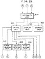
- the electrical system includes an arithmetic unit 600, a control unit 610, a display unit 700, a storage unit 800, a first driving unit 910 and a second driving unit 920.
- the control unit 610 controls the first light source 100, the first driving unit 910 and the second driving unit 920 according to control signals given thereto by the arithmetic unit 600.
- the first driving unit 910 drives the first cylindrical lens 220a of the first illuminating optical system 200A according to a signal given to the arithmetic unit 600 by the first photodetecting device 510.
- the first driving unit 910 drives a lens moving mechanism to turn the first cylindrical lens 220a.
- the second driving unit 920 drives the second cylindrical lens 320a of the photodetecting optical system 300A according to a signal given to the arithmetic unit 600 by the first photodetecting device 510.
- the second driving unit 920 drives a lens moving mechanism to turn the second cylindrical lens 320a.
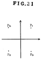
- Each of the cylindrical lenses 220a and 320a have a pair of cylindrical lenses.
- cylinders have cylindrical powers D and -D
- the cylinders are placed in a coordinate system defined by an x-axis and a y-axis perpendicular to the x-axis, and the respective axes of the cylinders having the cylindrical powers D and -D are inclined to the x-axis at ⁇ + and ⁇ v.
- astigmatisms at an angle ⁇ is: D ⁇ cos2( ⁇ - ⁇ + ) -D ⁇ cos2( ⁇ - ⁇ - )
- the first driving unit 910, the second driving unit 920 and the lens moving mechanisms correspond to the image forming condition changing unit that changes the respective image forming conditions of the first illuminating optical system 200 and the first photodetecting optical system 300.
- step S3 the control unit 610 controls the first driving unit 910 and the second driving unit 920 according to control signals provided by the arithmetic unit 600 to set the movable units at their initial positions; that is the first driving unit 910 moves the first illuminating optical system 200A to its initial position by driving a lens moving mechanism, and the second driving unit 920 moves the photodetecting optical system 300A to its initial position by driving a lens moving mechanism.
- a measurement preparation procedure A is executed in step S4.
- the measurement preparation procedure A will be described with reference to Fig. 4.
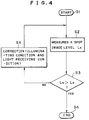
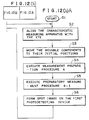
- the measurement preparation procedure A is started in step Sl.
- the first photodetecting device 510 measures a spot image level Ls in step S2.
- the arithmetic unit 600 decides whether the spot image level L s is higher than a predetermined level Lo in step S3. If the spot image level Ls is higher than the predetermined level L 0 , the procedure proceeds to step S4 to end the measuring preparation procedure.
- the measurement preparation procedure A makes a decision on the basis of the spot image level Ls in the first embodiment
- the arithmetic unit 600 decides that the distribution of spots of the beams transformed by the transforming device 400 on the first photodetecting device 510 is excessively dense
- the image forming conditions of the first illuminating optical system 200A and the first photodetecting optical system 300A may be changed so that the spots of the light beams are distributed properly on the first photodetecting device 510 by a preparatory measurement procedure B, which will be describe later in connection with a second modification of a second embodiment.
- step S3 If it is decided in step S3 that the spot image level Ls is not higher than the predetermined level L 0 , the image forming condition changing unit is controlled to correct illuminating conditions and light receiving conditions in step S5.
- the arithmetic unit 600 controls the first driving unit 910 to move the illuminating optical system 200A for correcting illuminating conditions.
- the arithmetic unit 600 controls the second driving unit 920 to move the photodetecting optical system 300A to correct light receiving conditions. After the completion of the correction of the illuminating conditions and light receiving conditions in step S5, the procedure returns to step S2.
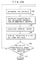
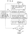
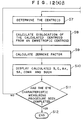
- a spot image is formed on the first photodetecting device 510 in step S5.
- the centroid of the spot image is determined in step S6.
- the centroid can be determined, for example, by projecting light on a plurality of pixels on the light receiving surface and measuring light intensities on the pixels.
- the position of the centroid can be measured in an accuracy not greater than 1/10 of the element.
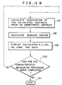
- step S7 dislocation of the measured centroid from an emmetropic centroid is calculated.
- step S8 Zernike factor is calculated by using Expressions (1) to (6), which will be described later.
- step S9 the calculated spherical power, cylindrical power, angle of astigmatic axis, spherical aberration, coma and other high-order aberration components (S, C, Ax, SA, Coma and such) of the eye are displayed on the screen of the display unit 700.
- step S10 A query is made in step S10 to see whether the eye characteristic measuring procedure has been completed. If the eye characteristic measuring procedure has been completed, the eye characteristic measuring procedure is ended in step Sll. If the eye characteristic measuring procedure has not yet been completed, the eye characteristic measuring procedure returns to step S2.
- the changeable illuminating conditions of the first illuminating optical system 200A are those concerned with the focused state of the illuminating light for illuminating the fundus.
- the image forming conditions that can be changed by the image forming condition changing unit may be those concerned with the condensed state of the light received by the first photodetecting device 510.
- the image forming condition changing unit of the first embodiment changes the image forming conditions of the first illuminating optical system 200A and the first photodetecting optical system 300A according to the level of the first signal provided by the first photodetecting device 510.
- An image forming condition changing unit included in the first modification of the first embodiment changes the image forming conditions of the first illuminating optical system 200A and the first photodetecting optical system 300A according to optical characteristics determined by the arithmetic unit 600.
- step Sl The alignment of the eye characteristic measuring apparatus with the eye is adjusted in step S2.
- step S3 the control unit 610 controls the first driving unit 910 and the second driving unit 920 according to control signals provided by the arithmetic unit 600 to set the movable units at their initial positions; that is the first driving unit 910 moves the first illuminating optical system 200A to its initial position by driving a lens moving mechanism, and the second driving unit 920 moves the photodetecting optical system 300A to its initial position by driving a lens moving mechanism.
- a preparatory measurement procedure B-1 is executed in step S4.
- the preparatory measurement procedure B-1 will be described with reference to Fig. 6.
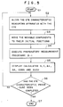
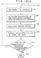
- the preparatory measurement procedure B-1 is started in step S1.
- a spot image is formed on the first photodetecting device 510 in step S2.
- the centroid of the spot image is determined, for example, on the basis of the respective intensities of light rays falling on a plurality of pixels on the light receiving surface.
- the position of the centroid can be calculated in an accuracy not greater than 1/10 of the element.
- the dislocation of the calculated centroid from an emmetropic centroid is calculated in step S4.
- step S5 Zernike factor is calculated by using Expressions (1) to (6), which will be described later.
- a correction Dl is calculated on the basis of the values of spherical power, cylindrical power and angle of astigmatic axis (S, C, Ax) calculated in step S5.
- step S6 a query is made to see if a correction D2 meets an inequality:
- a correction D2' is added to the correction D2, and the image forming condition changing unit is controlled to correct illuminating conditions and light receiving conditions in step S8; that is the arithmetic unit 600 controls the first driving unit 910 to change illuminating conditions by moving the first illuminating optical system 200A for correction.
- the arithmetic unit 600 controls the second driving unit 920 to change light receiving conditions for correction by moving the photodetecting optical system 300A.
- step S5 after the completion of the preparatory measurement procedure B-1 in step S4, the calculated spherical power, cylindrical power, angle of astigmatic axis, spherical aberration, coma and other high-order aberration components (S, C, Ax, SA, Coma and such) of the eye are displayed on the screen of the display unit 700 in step S5.
- step S6 A query is made in step S6 to see whether the eye characteristic measuring procedure has been completed. If the eye characteristic measuring procedure has been completed, the eye characteristic measuring procedure is ended in step S7. If the eye characteristic measuring procedure has not yet been completed, the eye characteristic measuring procedure returns to step S2.
- the image forming condition changing unit of the first embodiment changes the image forming conditions of the first illuminating optical system 200A and the first photodetecting optical system 300A according to the level of the first signal provided by the first photodetecting device 510.
- An image forming condition changing unit included in the second modification of the first embodiment changes the image forming conditions of the first illuminating optical system 200A and the first photodetecting optical system 300A according to the level of the first signal provided by the first photodetecting device 510 to set the first illuminating optical system 200A and the first photodetecting optical system 300A in a first changed state, and then changes the image forming conditions of the first illuminating optical system 200A and the first photodetecting optical system 300A according to optical characteristics determined by the arithmetic unit 600 to set the first illuminating optical system 200A and the first photodetecting optical system 300A in a second changed state.
- step S1 An eye characteristic measuring procedure to be carried out by the second modification of the eye characteristic measuring apparatus 10000 will be described with reference to Fig. 7.
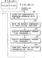
- the eye characteristic measuring procedure is started in step S1.
- the alignment of the eye characteristic measuring apparatus with the eye is adjusted in step S2.
- step S3 the control unit 610 controls the first driving unit 910 and the second driving unit 920 according to control signals provided by the arithmetic unit 600 to set the movable units at their initial positions; that is the first driving unit 910 moves the first illuminating optical system 200A to its initial position by driving a lens moving mechanism, and the second driving unit 920 moves the photodetecting optical system 300A to its initial position by driving a lens moving mechanism.
- the measurement preparation procedure A is carried out in step S4.
- the measurement preparation procedure A is the same as that shown in Fig. 4 and hence the description thereof will be omitted.
- step S5 After the completion of the measurement preparation procedure A in step S4, the preparatory measurement procedure B-1 is carried out in step S5.
- the preparatory measurement procedure B-1 is the same as that shown in Fig. 6 and hence the description thereof will be omitted.
- step S6 After the completion of the preparatory measurement procedure B-1 in step S5, the calculated spherical power, cylindrical power, angle of astigmatic axis, spherical aberration, coma and other high-order aberration components (S, C, Ax, SA, Coma and such) of the eye are displayed on the screen of the display unit 700 in step S6.
- step S7 A query is made in step S7 to see whether measurement has been completed.
- the eye characteristic measuring procedure is ended in step S8 if the response in step S7 is affirmative.
- the procedure returns to step S2 if the response in step S7 is negative.
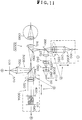
- an eye characteristic measuring apparatus 20000 in a second embodiment includes a first light source 100 that emits light of a first wavelength, a first illuminating optical system 200A capable of illuminating a small region of the retina of the eye 1000 with light emitted by the first light source 100 in various illuminating conditions, a first photodetecting optical system 300A that guides reflected light reflected from the retina of the eye 1000 through a first transforming device 400 that divides the reflected light into at least seventeen light beams to a first photodetecting device 510, a second photodetecting optical system 300B that guides reflected light reflected from the retina of the eye 1000 to a second photodetecting device 520, an arithmetic unit 600 that determines the optical characteristics of the eye 1000 on the basis of a first signal provided by the first photodetecting device 510 and corresponding to the inclination of the light, and an image forming condition changing unit that changes the respective image forming conditions of the first illuminating optical system 200A and the
- the arithmetic unit 600 determines the optical characteristics of the eye 1000 on the basis of the first signal provided by the first photodetecting device 510 and corresponding to the inclination of light.
- the image forming condition changing unit changes the image forming conditions for the first illuminating optical system 200A and the first photodetecting optical system 300A according to the level of the second signal provided by the second photodetecting device 520.
- the first photodetecting optical system 300A includes a first afocal lens 310, a second cylindrical lens 320a, a second relay lens 320b, a first beam splitter 330, a second beam splitter 340, and a transforming device 400 that divides the reflected light into at least seventeen light beams.
- the first photodetecting device 510 receives light traveling through the first photodetecting optical system 300A and the transforming device 400 and generates a first signal.
- the second photodetecting optical system 300B includes the first afocal lens 310, the second cylindrical lens 320a, the second relay lens 320b, the first beam splitter 330, the second beam splitter 340 and a second condenser lens 350.
- Light reflected by the second splitter 340 disposed between the second cylindrical lens 320 and the transforming device 400 travels through the second condenser lens 350 and falls on a second photodetecting device 520.
- the second photodetecting device 520 generates a second signal.
- the first light source 100 and the fundus of the eye 100 are conjugate to each other.
- the fundus of the eye 100 and the first and the second photodetecting device 510 and 520 are conjugate to each other.
- the transforming device 400 and the pupil of the eye 1000 are conjugate to each other.
- the eye characteristic measuring apparatus in the second embodiment is the same in other respects as that in the first embodiment and hence further description thereof will be omitted.
- the electrical system includes an arithmetic unit 600, a control unit 610, a display unit 700, a storage unit 800, a first driving unit 910 and a second driving unit 920.
- the arithmetic unit 600 receives the first signal from the first photodetecting device 510 and the second signal from the second photodetecting device 520.
- the arithmetic unit 600 determines the optical characteristics of the eye 1000 on the basis of the second signal provided by the second photodetecting device 520, controls the image forming condition changing unit to change the image forming conditions of the first illuminating optical system 200A and the first photodetecting optical system 300A.
- step S3 the control unit 610 controls the first driving unit 910 and the second driving unit 920 according to control signals provided by the arithmetic unit 600 to set the movable units at their initial positions; that is the first driving unit 910 moves the first illuminating optical system 200A to its initial position by driving a lens moving mechanism, and the second driving unit 920 moves the second cylindrical lens 320 of the photodetecting optical system 300A to its initial position by driving a lens moving mechanism.
- a measurement preparation procedure A is executed in step S4.
- the measurement preparation procedure A uses the second photodetecting device 520 as shown in Fig. 10.
- the measurement preparation procedure A will be described with reference to Fig. 10.
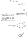
- the measurement preparation procedure A is started in step S1.
- the second photodetecting device 520 measures a spot image level L s in step S2.
- the arithmetic unit 600 decides whether the spot image level Ls is higher than a predetermined level Lo in step S3. If the spot image level L s is higher than the predetermined level Lo, the procedure proceeds to step S4 to end the measuring preparation procedure.
- step S3 If it is decided in step S3 that the spot image level L s is not higher than the predetermined level Lo, the image forming condition changing unit is controlled to correct illuminating conditions and light receiving conditions in step s5.
- the arithmetic unit 600 controls the first driving unit 910 to move the illuminating optical system 200A for correcting illuminating conditions.
- the arithmetic unit 600 controls the second driving unit 920 to move the photodetecting optical system 300A to correct light receiving conditions. After the completion of the correction of the illuminating conditions and light receiving conditions in step S5, the procedure returns to step S2.
- a spot image is formed on the first photodetecting device 510 in step S5.
- the centroid of the spot image is determined in step S6.
- the centroid can be determined, for example, by projecting light on a plurality of pixels on the light receiving surface and measuring light intensities on the pixels.
- the position of the centroid can be measured in an accuracy not greater than 1/10 of the element.
- step S7 dislocation of the measured centroid from an emmetropic centroid is calculated.
- step S8 Zernike factor is calculated by using Expressions (1) to (6).
- step S9 the calculated spherical power, cylindrical power, angle of astigmatic axis, spherical aberration, coma and other high-order aberration components (S, C, Ax, SA, Coma and such) of the eye are displayed on the screen of the display unit 700.
- step S10 A query is made in step S10 to see whether the eye characteristic measuring procedure has been completed. If the eye characteristic measuring procedure has been completed, the eye characteristic measuring procedure is ended in step S11. If the eye characteristic measuring procedure has not yet been completed, the eye characteristic measuring procedure returns to step S2.
- the image forming condition changing unit of the second embodiment changes the image forming conditions of the first illuminating optical system 200A and the first photodetecting optical system 300A according to the level of the second signal provided by the second photodetecting device 520.
- An image forming condition changing unit included in the first modification of the second embodiment changes the image forming conditions of the first illuminating optical system 200A and the first photodetecting optical system 300A according to the level of the second signal provided by the second photodetecting device 520 to set a first state, and sets a second state by changing the image forming conditions of the first illuminating optical system 200A and the first photodetecting optical system 300A according to optical characteristics determined by the arithmetic unit 600.
- the image forming conditions of the first illuminating optical system 200A and the first photodetecting optical system 300A makes the level of the second signal a maximum.
- the image forming conditions of the first illuminating optical system 200A and the first photodetecting optical system 300A are determined according to the optical characteristics of the eye including a spherical component, an astigmatic component and an axis of astigmatic axis so that those optical characteristics are cancelled out. More concretely, the spherical component is corrected approximately in the first state, and the spherical component is corrected precisely, the astigmatic component and the angle of astigmatic axis are corrected in the second state.
- the eye characteristic measuring procedure is started in step S1.
- the alignment of the eye characteristic measuring apparatus with the eye is adjusted in step S2.
- the control unit 610 controls the first driving unit 910 and the second driving unit 920 according to control signals provided by the arithmetic unit 600 to set the movable units at their initial positions; that is the first driving unit 910 and the second driving unit 920 are controlled so as to move the movable units its initial position, and the second driving unit 920 moves the photodetecting optical system 300A to its initial position by driving a lens moving mechanism.
- a measurement preparation procedure A is carried out in step S4.
- the measurement preparation procedure A is the same as that shown in Fig. 10 and described in connection with the second embodiment.
- the first state is set at the completion of the measurement preparation procedure A.
- a preparatory measurement procedure B-1 is executed in step S5.
- the preparatory measurement procedure B-1 is the same as that described in connection with the first modification of the first embodiment with reference to Fig. 6. Corrections are determined on the basis of a spherical power, a cylindrical power and an angle of astigmatic axis (S, C, Ax) and photodetecting conditions are changed on the basis of the corrections for correction.
- Step S6 to S10 are executed to measure the spherical power, cylindrical power, angle of astigmatic axis, spherical aberration, coma and other high-order aberration components (S, C, Ax, SA, Coma and such) of the eye and the measured data are displayed. Those steps are the same as those executed by the second embodiment and hence the further description thereof will be omitted.
- a query is made in step S11 to see whether the eye characteristic measuring procedure has been completed. If the eye characteristic measuring procedure has been completed, the eye characteristic measuring procedure is ended in step S12. If the eye characteristic measuring procedure has not yet been completed, the eye characteristic measuring procedure returns to step S2 and measurement is continued.
- the image forming condition changing unit of the second embodiment changes the image forming conditions of the first illuminating optical system 200A and the first photodetecting optical system 300A according to the level of the second signal provided by the second photodetecting device 520.
- An image forming condition changing unit included in the second modification of the second embodiment changes the image forming conditions of the first illuminating optical system 200A and the first photodetecting optical system 300A according to the level of the second signal provided by the second photodetecting device 520 to set a first state, and sets a second state by changing the image forming conditions of the first illuminating optical system 200A and the first photodetecting optical system 300A according to a signal provided by the first photodetecting device 510.
- the image forming conditions of the first illuminating optical system 200A and the first photodetecting optical system 300A makes the level of the second signal a maximum.
- the image forming conditions of the first illuminating optical system 200A and the first photodetecting optical system 300A are determined according to the level of a signal provided by the first photodetecting device 510 or the position of a light spot on the first photodetecting device 510. More concretely, the spherical component is corrected approximately in the first state, and the spherical component is corrected precisely, the astigmatic component and the angle of astigmatic axis are corrected in the second state.
- the eye characteristic measuring procedure is started in step S1.
- the alignment of the eye characteristic measuring apparatus with the eye is adjusted in step S2.
- the control unit 610 controls the first driving unit 910 and the second driving unit 920 according to control signals provided by the arithmetic unit 600 to set the movable units at their initial positions; that is the first driving unit 910 and the second driving unit 920 are controlled so as to move the movable units to their initial positions.
- the second driving unit 920 moves the photodetecting optical system 300A to its initial position by driving a lens moving mechanism.
- a measurement preparation procedure A is carried out in step S4.
- the measurement preparation procedure A is the same as that shown in Fig. 10 and described in connection with the second embodiment.
- the first state is set at the completion of the measurement preparation procedure A.
- a preparatory measurement procedure B is executed in step S5.
- the preparatory measurement procedure B changes the image forming conditions of the first illuminating optical system 200A and the first photodetecting optical system 300A according to a signal provided by the first photodetecting device 510.
- the image forming conditions of the first illuminating optical system 200A and the first photodetecting optical system 300A are changed so that the spots of the beams are distributed properly. For example, when the light is convergent, the image forming conditions are changed so that the degree of convergence of light is decreased.
- Step S6 to S10 are executed to measure the spherical power, cylindrical power, angle of astigmatic axis, spherical aberration, coma and other high-order aberration components (S, C, Ax, SA, Coma and such) of the eye to be displayed.
- steps S6 to S10 are the same as those executed by the second embodiment and hence the further description thereof will be omitted.
- a query is made in step S11 to see whether the eye characteristic measuring procedure has been completed. If the eye characteristic measuring procedure has been completed, the eye characteristic measuring procedure is ended in step S12. If the eye characteristic measuring procedure has not yet been completed, the eye characteristic measuring procedure returns to step S2.
- an eye characteristic measuring apparatus 30000 in a third embodiment according to the present invention includes a first light source 100 that emits light of a first wavelength, a first illuminating optical system 200A capable of illuminating a small region of the retina of the eye 1000 with light emitted by the first light source 100, a second light source that emits light of a second wavelength, a second illuminating optical system 200B capable of illuminating a predetermined region of the retina of the eye 100 with the light of the second wavelength emitted by the second light source 110, a first photodetecting optical system 300A that guides reflected light reflected from the retina of the eye 1000 through a first transforming device 400 that divides the reflected light into at least seventeen light beams to a first photodetecting device 510, a second photodetecting optical system 300B that guides reflected light reflected from the retina of the eye 1000 to a second photodetecting.
- an arithmetic unit 600 that determines the optical characteristics of the eye 1000 on the basis of a first signal provided by the first photodetecting device 510 and corresponding to the inclination of the light and determines the illuminating conditions of the first illuminating optical system 200A on the basis of a second signal provided by the second photodetecting device 520, and an image forming condition changing unit that changes the respective image forming conditions of the first illuminating optical system 200A and the first photodetecting optical system 300A according to the level of a first signal provided by the first photodetecting device 510 to set a first changed state and changes the image forming conditions of the first illuminating optical system 200A and the first photodetecting optical system 300A according to the optical characteristics determined by the arithmetic unit 600 to set a second changed state.
- the first illuminating optical system 200A illuminates a small region of the retina of the eye 1000 with the light emitted by the first light source 100.
- the first illuminating optical system 200A includes a first condenser lens 210, a first cylindrical lens 220a and a first relay lens 220b.
- the second illuminating optical system 200B illuminates a predetermined region of the retina of the eye with the second light emitted by the second light source 110.
- the second wavelength of the second light emitted by the second light source 110 is, for example, 860 nm.
- the second illuminating optical system 200B includes the second light source 110, a third condenser lens 230, a first diaphragm ring 240, a fourth condenser lens 250, a second diaphragm ring 260, a lens 270 and a third beam splitter 330.
- the third condenser lens 230 and the first diaphragm ring 240 are for the illumination of the pupil.
- the fourth condenser lens 250 and the second diaphragm ring 260 are for the illumination of the fundus.
- the first photodetecting optical system 300A guides reflected light reflected from the retina of the eye and passing the second beam splitter 340 to the first photodetecting device 510.
- the first photodetecting optical system 300A includes a first afocal lens 310, a second cylindrical lens 320a, a second relay lens 320b, a first beam splitter 330 and a transforming device 400 that divides the reflected light into at least seventeen light beams.
- the first photodetecting device 510 receives the light beams provided by the transforming device 400 of the first photodetecting optical system 300A and generates a first signal.
- the second photodetecting optical system 300B includes the first afocal lens 310, the first beam splitter 330, a second beam splitter 340 and a second condenser lens 350.
- the light of the second wavelength reflected by the second beam splitter 340 disposed between the first beam splitter 330 and the second cylindrical lens 320 travels through the second condenser lens 350 and falls on the second photodetecting device 520.
- the second photodetecting device 520 generates a second signal.
- the second beam splitter 340 is a dichroic mirror that transmits the light of the first wave length and reflects the light of the second wavelength.
- the first light source 100 and the second diaphragm ring 260 corresponding to the secondary light source of the second light source 110 are conjugate to the fundus of the eye 1000.
- the first photodetecting device 510 and the second photodetecting device 520 are conjugate to the fundus of the eye 1000.
- the transforming device 400 and the pupil are conjugate to each other.
- the pupil and the first diaphragm ring 240 are conjugate to each other.
- the third embodiment is the same in other respects as the first and the second embodiment and hence the further description thereof will be omitted.
- the electrical system includes an arithmetic unit 600, a control unit 610, a display unit 700, a storage unit 800, a first driving unit 910 and a second driving unit 920.
- the arithmetic unit 600 receives the first signal from the first photodetecting device 510 and a second signal from the second photodetecting device 520.
- the arithmetic unit 600 determines the optical characteristics of the eye 1000 on the basis of the first signal provided by the first photodetecting device 510 and determines the illuminating condition of the first illuminating optical system 200A on the basis of the second signal provided by the second photodetecting device 520.
- An image forming condition changing unit included in the third embodiment changes the image forming conditions of the first illuminating optical system 200A and the first photodetecting optical system 300A according to the level of the second signal provided by the second photodetecting device 520 to set a first changed state, and sets a second changed state by changing the image forming conditions of the first illuminating optical system 200A and the first photodetecting optical system 300A according to optical characteristics determined by the arithmetic unit 600.
- the second wavelength may be shorter than the first wavelength.
- the first and the second wavelength may be equal and the second beam splitter 340 may be replaced with a semitransparent mirror.
- the first illuminating optical system 200A and the second illuminating optical system 200B may be of the same configuration.
- the eye characteristic measuring procedure is started in step S1.
- the alignment of the eye characteristic measuring apparatus with the eye is adjusted in step S2.
- the control unit 610 controls the first driving unit 910 and the second driving unit 920 according to control signals provided by the arithmetic unit 600 to set the movable units at their initial positions; that is the first driving unit 910 moves the first illuminating optical system 200A to its initial position by driving a lens moving mechanism, and the second driving unit 920 moves the photodetecting optical system 300A to its initial position by driving a lens moving mechanism.
- a measurement preparation procedure A is carried out in step S4.
- the measurement preparation procedure A is the same as that shown in Fig. 4 and described in connection with the first embodiment.
- the first state is set at the completion of the measurement preparation procedure A.
- a preparatory measurement procedure B-2 is executed in step S5.
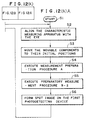
- the preparatory measurement procedure B-2 will be described with reference to Fig. 13.
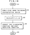
- step S2 a ring image is formed on the second photodetecting device 520 by illuminating the pupil or the fundus by the second illuminating optical system 200B and detecting the reflected second light reflected from the retina of the eye 1000 by the second photodetecting device 520.
- the ring image is an image of the second diaphragm ring 260.
- step S3 the arithmetic unit 600 calculates spherical power, cylindrical power and angle of astigmatic axis (S, C and Ax).
- step S4 the image forming condition changing unit is controlled according to the spherical power, cylindrical power and angle of astigmatic axis (S, C and Ax) calculated by the arithmetic unit 600 to correct the illuminating condition and the light receiving condition.
- This state corresponds to the second state.
- step S4 illuminating conditions and light receiving conditions are corrected and the preparatory measurement procedure B-2 is ended in step S5.
- a spot image is formed on the first photodetecting device 510 in step S6.
- the centroid of the spot image is determined in step S7.
- the centroid can be determined, for example, by projecting light on a plurality of pixels on the light receiving surface and measuring light intensities on the pixels.
- the position of the centroid can be measured in an accuracy not greater than 1/10 of the element.
- step S8 dislocation of the measured centroid from an emmetropic centroid is calculated.
- step S9 Zernike factor is calculated by using Expressions (1) to (6), which will be described later.
- step S10 the calculated spherical power, cylindrical power, angle of astigmatic axis, spherical aberration, coma and other high-order aberration components (S, C, Ax, SA, Coma and such) of the eye are displayed on the screen of the display unit 700.
- step S11 A query is made in step S11 to see whether the eye characteristic measuring procedure has been completed. If the eye characteristic measuring procedure has been completed, the eye characteristic measuring procedure is ended in step S12. If the eye characteristic measuring procedure has not yet been completed, the eye characteristic measuring procedure returns to step S2.
- the image forming condition changing unit changes the image forming conditions of the first illuminating optical system 200A and the first photodetecting optical system 300A according to the level of the second signal provided by the second photodetecting device 520 to set the first changed state, and changes the image forming conditions of the first illuminating optical system 200A and the first photodetecting optical system 300A according to optical characteristics determined by the arithmetic unit 600 to set the second changed state.
- the image forming condition changing unit changes the image forming conditions of the first illuminating optical system 200A and the first photodetecting optical system 300A according the optical characteristics determined by the arithmetic unit 600.
- step S1 The alignment of the eye characteristic measuring apparatus with the eye is adjusted in step S2.
- step S3 the control unit 610 controls the first driving unit 910 and the second driving unit 920 according to control signals provided by the arithmetic unit 600 to set the movable units at their initial positions; that is the first driving unit 910 drives a lens moving mechanism to move the first cylindrical lens 220 of the first illuminating optical system 200A to its initial position.
- the second driving unit 920 drives a lens moving mechanism to move the second cylindrical lens 320 of the photodetecting optical system 300A to its initial position.
- a preparatory measurement procedure B-2 is executed in step S4.
- the measurement preparation procedure B-2 is the same as the preparatory measurement procedure B-2 previously described with reference to Fig. 13 in connection with the third embodiment and hence the description thereof will be omitted.
- a spot image is formed on the first photodetecting device 510 in step S5.
- the centroid of the spot image is determined in step S6.
- the centroid can be determined, for example, by projecting light on a plurality of pixels on the light receiving surface and measuring light intensities on the pixels.
- the position of the centroid can be measured in an accuracy not greater than 1/10 of the element.
- step S7 dislocation of the measured centroid from an emmetropic centroid is calculated.
- step S8 Zernike factor is calculated by using Expressions (4) and (5), which will be described later.
- step S9 the calculated spherical power, cylindrical power, angle of astigmatic axis, spherical aberration, coma and other high-order aberration components (S, C, Ax, SA, Coma and such) of the eye are displayed on the screen of the display unit 700.
- step S10 A query is made in step S10 to see whether the eye characteristic measuring procedure has been completed. If the eye characteristic measuring procedure has been completed, the eye characteristic measuring procedure is ended in step S11. If the eye characteristic measuring procedure has not yet been completed, the eye characteristic measuring procedure returns to step S2
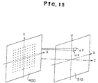
- the principle of operation of the arithmetic unit 600 for determining the optical characteristics of the eye 1000 on the basis of the first signal provided by the first photodetecting device 510 and corresponding to the inclination of light will be explained.
- the present invention is intended to measure the wave aberration of the eye.
- a coordinate system XY is defined by an x-axis and a Y-axis on the transforming device 400 and a coordinate system xy is defined by an x-axis and a y-axis on the first photodetecting device 510.
- Both sides of Expression (3) are differentiated by X and Y to obtain derivatives, and the derivatives are substituted into the left sides of Expressions (1) and (2) to obtain a polynomial of Cij .
- Z ij of Expression (3) is called Zernike polynomial expressed by Expressions (4) and (5). where when n-2m>0, sin is applied and when n-2m ⁇ 0, cos is applied.
- the C ij thus determined are important optical parameters of the eye.
- an eye characteristic measuring apparatus 40000 in a fourth embodiment according to the present invention includes a first light source 100 that emits first light of a first wavelength, a first illuminating optical system 200A that illuminates a small region of the retina of the eye with the first light emitted by the first light source 100, a first photodetecting optical system 300A that guides part of the reflected light reflected from the retina of the eye through a first transforming member 400 that divides the reflected light into at least seventeen light beams to a first photodetecting device 510, a second photodetecting optical system 300B that guides part of reflected second light reflected from the retina of the eye through a second transforming member 410 that divides the reflected light into at least four light beams to a second photodetecting device 520, an anterior segment illuminating light source 110 that emits light of a second wavelength for illuminating an anterior segment of the eye, an anterior segment illuminating optical system 200B that illuminates a predetermined region of an anterior segment of the eye with the light
- the second illuminating optical system 200B illuminates the predetermined region of the anterior segment of the eye with the second light emitted by the second light source 110.
- the second illuminating optical system 200B includes the second light source 110, a fifth condenser lens 290, a fourth beam splitter 350, a fifth beam splitter 360, a first beam splitter 330 and a first afocal lens 310.
- a Z-alignment optical system 5100 includes a fourth light source 5110, a collimator lens 5120, a condenser lens 5130 and a fourth photodetecting device 5140.
- the alignment adjusting operation adjusts the positional relation between the eye and the eye characteristic measuring apparatus with respect to a direction perpendicular to the optical axis by using the light emitted by the second light source 110 and reflected by the anterior segment of the eye.
- the light emitted by the second light source 110 is guided through the fifth condenser lens 290, the fourth beam splitter 350, the fifth beam splitter 360 and the first afocal lens 310 to illuminate the eye with substantially parallel light rays.
- Reflected light reflected from the cornea of the eye diverges in divergent light rays as if the light rays are emitted from a point at half the radius of curvature of the cornea.
- the divergent light rays are converged by the first afocal lens 310 and the fifth condenser lens 290 in a spot image on the anterior segment photodetecting device 530.
- the eye characteristic measuring apparatus is moved in a plane perpendicular to the optical axis.
- the spot image lies on the optical axis on the anterior segment photodetecting device 530, the eye characteristic measuring apparatus is aligned with the eye.
- the wavelength of the second light emitted by the second light source 110 is longer than that of the first light emitted by the first light source 100 and is, for example, 940 nm.
- a dichroic mirror that transmits the first light emitted by the first light source 100 and reflects the second light emitted by the second light source 110 is used as the second beam splitter 340 to prevent the first light and the second light from falling on the wrong optical systems, respectively, to generate noise.
- an image of the eye is formed on the anterior segment photodetecting device 530.
- the image of the eye may be used for alignment adjustment; the position of the eye characteristic measuring apparatus relative to the eye is adjusted so that the center of the pupil of the eye coincides with the optical axis.
- Operating distance adjustment is achieved by emitting parallel light rays by the fourth light source 5110 along the optical axis toward the eye, and receiving the reflected light reflected from the eye through the condenser lens by the fourth photodetecting device 5140.
- a spot image of the fourth light source 5110 is formed at a position on the fourth photodetecting device 5140 where the optical axis intersects the fourth photodetecting device 5140. If the eye is not at the appropriate operating distance, the spot image deviates vertically from the position on the fourth photodetecting device 5140 where the optical axis intersects the fourth photodetecting device 5140.
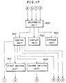
- An electrical system included in the eye characteristic measuring apparatus 40000 will be described with reference to Fig. 17.
- An arithmetic unit 600 included in the electrical system receives signals from the second photodetecting device 520, the third photodetecting device 530 and the fourth photodetecting device 5140 in addition to the signal received by the arithmetic unit 600 shown in Fig. 2.
- a control unit 610 included in the electrical system controls additionally the second light source 110, the fourth light source 5110 and the illuminating light sources 6000.
- the electrical system is the same in other respects as that of the second embodiment and hence the further description thereof will be omitted.
- the eye characteristic measuring procedure is similar to that shown in Fig. 3, except that a step S41 for a preparatory measurement procedure B-3 is interposed between steps S4 and S5.
- the second photodetecting optical system 300B including the second transforming device 410 carries out coarse measurement (second state).
- the first photodetecting optical system 300A including the first transforming device 400 carries out precise measurement (first state) .
- measurement can be achieved in a shorter time.
- the first transforming device 400 divides the first reflected light into at least seventeen light beams.
- the second transforming device divides the second reflected light into at least four light beams.
- the second transforming device 410 is provided with four lenses 411.
- the respectively foci of the lenses 411 are determined so that the positions of images formed by the lenses 411 of the second transforming device 410 coincide substantially with that of an image formed by the second transforming device 410.
- dx (L - h)/2
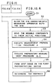
- the preparatory measurement procedure B-3 is started in step S1, a spot image is formed on the second photodetecting device 520 in step S2 and the measurement is carried out in step s3.
- step S4 A query is made in step S4 to see whether the position of the centroid of each aperture are measured correctly in step S3. If the response in step S4 is negative, the movable components are moved to another diopter D in step S5 and the procedure returns to step S3. If the response in step S4 is affirmative, the movable components are moved by a distance corresponding to the measured diopter D in step S6. Measurement is repeated in step S7. A query is made in step S8 to see whether the measured diopter D is small. If the response in step S8 is negative, the movable components are moved by a distance corresponding to a small diopter D' in the direction of the sign of the measured diopter D in step S9 and the procedure returns to step S7.
- step S8 If the response in step S8 is affirmative, the preparatory measurement procedure B-3 is ended in step S10.
- the preparatory measurement procedure B-3 is carried out in step S41.
- the preparatory measurement procedure B-3 is the same in other respects as the procedure shown in Fig. 3 and hence the further description thereof will be omitted.
- the measurement preparation procedure A to be carried out in step S4 may be omitted.
- the eye characteristic measuring apparatus in the modification is not provided with any optical system corresponding to the second photodetecting optical system 300B, and the first transforming device 400 or the second transforming device 410 can be selectively inserted in the first photodetecting optical system 300A.
- the first transforming device 400 is used for precise measurement and the second transforming device 410 is used for rough measurement.
- the first photodetecting optical system 300A is provided with a changing mechanism 7000 for selectively inserting the first transforming device 400 or the second transforming device 410 into the first photodetecting optical system 300A. As shown in Fig. 23, the changing mechanism 7000 is driven by a third driving unit 930.
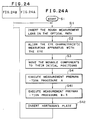
- An eye characteristic measuring procedure shown in Fig. 24 is similar to that shown in Fig. 3, except that step S11 for rough measurement lens insertion is interposed between steps S1 and S2, step S41 for preparatory measurement procedure B-3 is interposed between step S4 and S5, and the eye characteristic measuring procedure includes an additional step S42 for Hartmann's plate insertion.
- step S11 the changing mechanism 7000 inserts the second transforming device 410 in the optical path for rough measurement.
- step S41 the same preparatory measurement procedure B-3 as that carried out by the fourth embodiment is carried out in step S41.
- step S42 the changing mechanism 7000 inserts the first transforming device 400 for precise measurement.
- the second transforming device 410 may be provided with apertures greater than those of the first transforming device 400.
- the apertures of the second transforming device 410 may be arranged at intervals greater than those at which the apertures of the first transforming device 400 are arranged.
- the number of the light beams may be smaller than that of the light beams for the first state (precise measurement).
- a mask for reducing the number of the light beams may be disposed near the first transforming device 400.
- a mask that does not make the reflected light pass through the adjacent apertures may be disposed near the first transforming device 400.
- the eye characteristic measuring apparatus comprises the first light source that emits the light of the first wavelength, the first illuminating optical system capable of illuminating a small region of the retina of the eye in a variable illuminating condition, the first photodetecting optical system provided with the first photodetecting device that receives part of the reflected light reflected from the retina through the first transforming device that divides the reflected light beam into at least seventeen light beams, the arithmetic unit that determines the optical characteristics of the eye on the basis of the first signal provided by the first photodetecting device and corresponding to the inclination of the light beam, and the image forming condition changing unit that changes the respective image forming conditions of the first illuminating optical system and the first photodetecting optical system according to the level of the first signal provided by the first photodetecting device.
- the image forming condition changing unit sets optimum illuminating and light receiving conditions, so that the optical characteristics of the eye can be highly accurately measured.
Landscapes
- Physics & Mathematics (AREA)
- Health & Medical Sciences (AREA)
- Life Sciences & Earth Sciences (AREA)
- Spectroscopy & Molecular Physics (AREA)
- Medical Informatics (AREA)
- Animal Behavior & Ethology (AREA)
- Biomedical Technology (AREA)
- Heart & Thoracic Surgery (AREA)
- Ophthalmology & Optometry (AREA)
- Molecular Biology (AREA)
- Surgery (AREA)
- Engineering & Computer Science (AREA)
- General Health & Medical Sciences (AREA)
- Public Health (AREA)
- Veterinary Medicine (AREA)
- Biophysics (AREA)
- General Physics & Mathematics (AREA)
- Eye Examination Apparatus (AREA)
Applications Claiming Priority (6)
| Application Number | Priority Date | Filing Date | Title |
|---|---|---|---|
| JP32474499 | 1999-11-15 | ||
| JP32474499 | 1999-11-15 | ||
| JP2000318640 | 2000-10-18 | ||
| JP2000318640A JP4692939B2 (ja) | 1999-11-15 | 2000-10-18 | 眼特性測定装置 |
| JP2000321509A JP4618593B2 (ja) | 2000-10-20 | 2000-10-20 | 眼特性測定装置 |
| JP2000321509 | 2000-10-20 |
Publications (2)
| Publication Number | Publication Date |
|---|---|
| EP1104663A2 true EP1104663A2 (de) | 2001-06-06 |
| EP1104663A3 EP1104663A3 (de) | 2005-01-19 |
Family
ID=27340069
Family Applications (1)
| Application Number | Title | Priority Date | Filing Date |
|---|---|---|---|
| EP00124288A Withdrawn EP1104663A3 (de) | 1999-11-15 | 2000-11-14 | Messvorrichtung zur Ermittlung von Augenaberrationen |
Country Status (2)
| Country | Link |
|---|---|
| US (1) | US6629761B1 (de) |
| EP (1) | EP1104663A3 (de) |
Cited By (1)
| Publication number | Priority date | Publication date | Assignee | Title |
|---|---|---|---|---|
| WO2001047407A1 (en) | 1999-12-27 | 2001-07-05 | Kabushiki Kaisha Topcon | Optical characteristic measuring instrument |
Families Citing this family (9)
| Publication number | Priority date | Publication date | Assignee | Title |
|---|---|---|---|---|
| DE19938203A1 (de) * | 1999-08-11 | 2001-02-15 | Aesculap Meditec Gmbh | Verfahren und Vorrichtung zur Korrektur von Sehfehlern des menschlichen Auges |
| JP4606560B2 (ja) * | 2000-10-10 | 2011-01-05 | 株式会社トプコン | 眼光学特性測定装置 |
| JP4630126B2 (ja) * | 2005-05-16 | 2011-02-09 | 株式会社トプコン | 眼光学特性測定装置 |
| US7475989B2 (en) | 2006-03-14 | 2009-01-13 | Amo Manufacturing Usa, Llc | Shack-Hartmann based integrated autorefraction and wavefront measurements of the eye |
| AU2008251316B2 (en) | 2007-05-11 | 2014-05-29 | Amo Development, Llc | Combined wavefront and topography systems and methods |
| US7976163B2 (en) * | 2007-06-27 | 2011-07-12 | Amo Wavefront Sciences Llc | System and method for measuring corneal topography |
| US7988290B2 (en) | 2007-06-27 | 2011-08-02 | AMO Wavefront Sciences LLC. | Systems and methods for measuring the shape and location of an object |
| US7896498B2 (en) * | 2009-03-30 | 2011-03-01 | Ottawa Hospital Research Institute | Apparatus and method for optical measurements |
| US8622546B2 (en) | 2011-06-08 | 2014-01-07 | Amo Wavefront Sciences, Llc | Method of locating valid light spots for optical measurement and optical measurement instrument employing method of locating valid light spots |
Family Cites Families (7)
| Publication number | Priority date | Publication date | Assignee | Title |
|---|---|---|---|---|
| JPS56151929A (en) * | 1980-04-25 | 1981-11-25 | Canon Inc | Fundus camera |
| DE4222395A1 (de) * | 1992-07-08 | 1994-01-13 | Amtech Ges Fuer Angewandte Mic | Vorrichtung und Verfahren zur Messung der Augenrefraktion |
| US5777719A (en) * | 1996-12-23 | 1998-07-07 | University Of Rochester | Method and apparatus for improving vision and the resolution of retinal images |
| US6234978B1 (en) * | 1997-02-12 | 2001-05-22 | Kabushiki Kaisha Topcon | Optical characteristic measuring apparatus |
| US5929970A (en) * | 1997-05-13 | 1999-07-27 | Kabushiki Kaisha Topcon | Optical characteristic measuring apparatus |
| DK1032809T3 (da) * | 1997-11-21 | 2007-05-14 | Alcon Inc | Objektiv måling og korrektion af optiske systemer ved anvendelse af bölgefrontanalyse |
| JP2001095760A (ja) * | 1999-09-28 | 2001-04-10 | Topcon Corp | 眼の光学特性測定装置 |
-
2000
- 2000-11-14 EP EP00124288A patent/EP1104663A3/de not_active Withdrawn
- 2000-11-15 US US09/713,790 patent/US6629761B1/en not_active Expired - Fee Related
Cited By (2)
| Publication number | Priority date | Publication date | Assignee | Title |
|---|---|---|---|---|
| WO2001047407A1 (en) | 1999-12-27 | 2001-07-05 | Kabushiki Kaisha Topcon | Optical characteristic measuring instrument |
| EP1157657A4 (de) * | 1999-12-27 | 2007-08-08 | Topcon Corp | Vorrichtung zur messung optischer charakteristik |
Also Published As
| Publication number | Publication date |
|---|---|
| EP1104663A3 (de) | 2005-01-19 |
| US6629761B1 (en) | 2003-10-07 |
Similar Documents
| Publication | Publication Date | Title |
|---|---|---|
| US6070981A (en) | Ophthalmologic characteristic measuring apparatus | |
| JP5191622B2 (ja) | 波面分析システムおよびその合焦方法 | |
| US5463430A (en) | Examination apparatus for examining an object having a spheroidal reflective surface | |
| US6802609B2 (en) | Eye characteristic measuring apparatus | |
| US6536900B2 (en) | Eye characteristic measuring apparatus | |
| EP1157657A1 (de) | Vorrichtung zur messung optischer charakteristik | |
| JP4167979B2 (ja) | 眼型器官の収差を測定する装置 | |
| US20100045934A1 (en) | Dynamic range extension techniques for a wavefront sensor including use in ophthalmic measurement | |
| EP1295559A2 (de) | Verfahren und Vorrichtung zur Messung optischer Aberrationen eines Auges | |
| JP2005501640A (ja) | 眼用波面測定装置 | |
| US6629761B1 (en) | Eye characteristic measuring apparatus | |
| JPWO2001047407A1 (ja) | 光学特性の測定装置 | |
| US5302979A (en) | Ophthalmic apparatus capable of measuring the shape of a cornea | |
| JPH08103413A (ja) | 眼科測定装置 | |
| US4679921A (en) | Apparatus for eye examination | |
| US20030073984A1 (en) | Corneal-ablation-data determining apparatus and a corneal surgery apparatus | |
| JP4692939B2 (ja) | 眼特性測定装置 | |
| US6676258B2 (en) | Eye characteristic measurement apparatus with speckle noise reduction | |
| US7249852B2 (en) | Eye characteristic measuring apparatus | |
| USRE39882E1 (en) | Ophthalmologic characteristic measuring apparatus | |
| US4929076A (en) | Ophthalmic measuring apparatus | |
| JP4618593B2 (ja) | 眼特性測定装置 | |
| US5101826A (en) | Noncontact type tonometer | |
| US20060256286A1 (en) | Eye's optical characteristics measuring system | |
| US7275828B2 (en) | Eye refractive power measurement apparatus |
Legal Events
| Date | Code | Title | Description |
|---|---|---|---|
| PUAI | Public reference made under article 153(3) epc to a published international application that has entered the european phase |
Free format text: ORIGINAL CODE: 0009012 |
|
| AK | Designated contracting states |
Kind code of ref document: A2 Designated state(s): AT BE CH CY DE DK ES FI FR GB GR IE IT LI LU MC NL PT SE TR |
|
| AX | Request for extension of the european patent |
Free format text: AL;LT;LV;MK;RO;SI |
|
| PUAL | Search report despatched |
Free format text: ORIGINAL CODE: 0009013 |
|
| AK | Designated contracting states |
Kind code of ref document: A3 Designated state(s): AT BE CH CY DE DK ES FI FR GB GR IE IT LI LU MC NL PT SE TR |
|
| AX | Request for extension of the european patent |
Extension state: AL LT LV MK RO SI |
|
| 17P | Request for examination filed |
Effective date: 20050523 |
|
| AKX | Designation fees paid |
Designated state(s): AT BE CH CY DE DK ES FI FR GB GR IE IT LI LU MC NL PT SE TR |
|
| 17Q | First examination report despatched |
Effective date: 20050726 |
|
| STAA | Information on the status of an ep patent application or granted ep patent |
Free format text: STATUS: THE APPLICATION IS DEEMED TO BE WITHDRAWN |
|
| 18D | Application deemed to be withdrawn |
Effective date: 20120605 |