EP1104864A1 - Soupape electromagnetique rotative - Google Patents
Soupape electromagnetique rotative Download PDFInfo
- Publication number
- EP1104864A1 EP1104864A1 EP99939898A EP99939898A EP1104864A1 EP 1104864 A1 EP1104864 A1 EP 1104864A1 EP 99939898 A EP99939898 A EP 99939898A EP 99939898 A EP99939898 A EP 99939898A EP 1104864 A1 EP1104864 A1 EP 1104864A1
- Authority
- EP
- European Patent Office
- Prior art keywords
- rotary
- valve
- electromagnet
- solenoid valve
- armature
- Prior art date
- Legal status (The legal status is an assumption and is not a legal conclusion. Google has not performed a legal analysis and makes no representation as to the accuracy of the status listed.)
- Granted
Links
- XEEYBQQBJWHFJM-UHFFFAOYSA-N Iron Chemical group [Fe] XEEYBQQBJWHFJM-UHFFFAOYSA-N 0.000 claims description 18
- 238000007789 sealing Methods 0.000 claims description 5
- 241001125929 Trisopterus luscus Species 0.000 claims 1
- 230000009885 systemic effect Effects 0.000 description 2
- 238000005299 abrasion Methods 0.000 description 1
- 230000001276 controlling effect Effects 0.000 description 1
- 238000009434 installation Methods 0.000 description 1
- 238000004519 manufacturing process Methods 0.000 description 1
- 230000010349 pulsation Effects 0.000 description 1
- 230000001105 regulatory effect Effects 0.000 description 1
Images


Classifications
-
- F—MECHANICAL ENGINEERING; LIGHTING; HEATING; WEAPONS; BLASTING
- F16—ENGINEERING ELEMENTS AND UNITS; GENERAL MEASURES FOR PRODUCING AND MAINTAINING EFFECTIVE FUNCTIONING OF MACHINES OR INSTALLATIONS; THERMAL INSULATION IN GENERAL
- F16K—VALVES; TAPS; COCKS; ACTUATING-FLOATS; DEVICES FOR VENTING OR AERATING
- F16K31/00—Actuating devices; Operating means; Releasing devices
- F16K31/02—Actuating devices; Operating means; Releasing devices electric; magnetic
- F16K31/06—Actuating devices; Operating means; Releasing devices electric; magnetic using a magnet, e.g. diaphragm valves, cutting off by means of a liquid
- F16K31/10—Actuating devices; Operating means; Releasing devices electric; magnetic using a magnet, e.g. diaphragm valves, cutting off by means of a liquid with additional mechanism between armature and closure member
-
- Y—GENERAL TAGGING OF NEW TECHNOLOGICAL DEVELOPMENTS; GENERAL TAGGING OF CROSS-SECTIONAL TECHNOLOGIES SPANNING OVER SEVERAL SECTIONS OF THE IPC; TECHNICAL SUBJECTS COVERED BY FORMER USPC CROSS-REFERENCE ART COLLECTIONS [XRACs] AND DIGESTS
- Y10—TECHNICAL SUBJECTS COVERED BY FORMER USPC
- Y10T—TECHNICAL SUBJECTS COVERED BY FORMER US CLASSIFICATION
- Y10T137/00—Fluid handling
- Y10T137/8593—Systems
- Y10T137/87917—Flow path with serial valves and/or closures
Definitions
- the invention relates to a gas solenoid valve, particularly to a closed rotary gas solenoid valve for gas flow control.
- a guardless solenoid electromagnet structure is employed in the current gas solenoid valve, which has a flatter pull characteristics, smaller attraction force, large power loss, typically no concurrent closing of the gas pipeline can be executed, conferring the characteristics shown in FIG.1.
- Aother type of gas solenoid valve adopts a solenoid guarded electromagnet, which has a rather steep pull characteristics as shown in FIG 2. Due to the constraint of the power consumption and bulk factors, when a larger flow is needed, an aperture enlargement of the gas solenoid valve and elongation of the operating stroke are required.
- a further type of the gas solenoid valve employs an epsilon structural clapper electromagnet having a rather steep pull characteristics, when the operating clearance is enlarging, its attraction attenuates rapidly, the solenoid valve is unable to realize the linear regulation of gas via the continuos current control, while the electromagnet can only reside in on-off state via the input of the square wave current to the coil, to attain the goal of the gas regulation through a variation of on-off time ratio of the electromagnet by changing the duty cycle of the on-off time.
- An object of the invention is to provide a rotary gas solenoid valve.
- Another object of the invention is, to provide a rotary gas solenoid valve, which can be utilized, not only for closing but also for continuous control.
- a further object of the invention is to provide a rotary gas solenoid valve having a small power loss, a large aperture, and long operating stroke.
- Still another object of the invention is to provide a double closure, continuously controlled gas solenoid valve.
- a rotator gas solenoid valve provided by the invention comprises a valve casing installed with an inlet and an outlet, also comprises at least a rotary electromagnet for controlling the valve port of the inlet or the opening and closing of the outlet.
- Said rotary gas solenoid valve in which rotary electromagnet is the guardless one, comprises an iron core, a coil, a rotary armature, and a seating, the electromagnet being installed on one side of the valve casing, a valve support being fastened on a position of an epitaxial end of the rotating armature shaft corresponding with the outlet valve port or the inlet valve port, and a valve member being mounted on the valve support.
- Said rotary gas solenoid valve in which the rotary electromagnet is the guarded one, comprises an iron core, a coil, a rotary armature, and a seating, the electromagnet being installed on one side of the valve casing, a valve support is fastened on the position of the expitaxial end of rotary armature shaft of the electromagnet corresponding with the outlet valve port or the inlet valve port, and the valve member is mounted on the valve support.
- a guardless rotary electromagnet is mounted on a side of the valve casing, a guarded rotary electromagnet is mounted on another side of the valve casing, said rotary gas solenoid valve comprises an iron core, a coil, a rotary armature, and a seating, a valve support being fastened on the position at the epitaxial end of armature shaft of the electromagnet corresponding with the outlet valve port or the inlet valve port, and the valve member being mounted on the valve support.
- a reset spring is mounted on its rotary electromagnet, its one end being fixed on the iron core or the seating, another end being mounted on an arm fastened with a side of the rotary armature or the epitaxial end of the armature shaft.
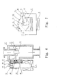
- the schematic of the first embodiment in the rotary gas solenoid of the invention is consisted of a valve casing 14 and a no-guarded rotary electromagnet mounted on a side of valve casing 14.
- Inlet and outlet valve port 11 are installed in the inner chamber of valve casing 14, and positioning hole 26 of the bearing case of the armature shaft is opened on a side plane of valve casing 14.
- the bearing case 19 of the electromagnet shaft 17 and the epitaxial end of the shaft 17 are mounted and positioned here, and the shaft 17 installed with a rubber sealing ring 20 is also in the positioning hole 26.
- the no-guarded rotary electromagnet 12 comprises an iron core 25, a coil 3, a rotary armature 24, a seating 18, and the rotary armature 24 being supported on the seating 18 fastened on the iron core 25 via shaft 17 and its bearing.
- a guardless electromagnet 22 is fixed on a side plane of the valve casing 14 via its iron core 25 and the seating 18.
- a reset spring 21 is installed between its rotary armature 24 and seating 18, an adjusting screw 23 is also mounted on the rest spring 21 for correcting the systemic error formed by various factors.
- a valve support 15 is fastened on the positron of the epitaxial end of shaft 17 corresponding to the outlet valve port 11, and the valve member 16 is mounted on the valve support 15. After coil 3 is energized, it can carry out the closing or the continuous regulation of the gas from outlet valve port 11 by way of a coil current variation.
- outlet valve port 11 is caused to be in closed state, thereby closing function is realized.
- said rotary gas solenoid valve consists of a valve casing 14 and a guarded rotary electromagnet 12 mounted on a side of valve casing 14.
- the inlet and outlet valve port 11 are installed in the inner chamber of the valve casing 14, a positioning hole 26 of the bearing case 19 of the armature shaft 17 is opened on a side plane of the valve casing 14, the bearing case 19 of the electromagnet shaft 17 and its epitaxial end are positioned and mounted here, and rubber sealing ring 20 is mounted on the shaft 17 in the positioning hole 26.
- the guarded rotary electromagnet comprises an iron core 25, a coil 3, a rotary armature 24 and a seating 18, the guarded rotary electromagnet 12 is fastened on a side plane of the valve casing 14 via its iron core 25 and the seating 18.
- a reset spring 21 is installed between its rotary armature 24 or an arm fastened by the spatial end of the armature shaft 17 and the seating 18 or the iron core 25.
- the valve support 15 is fastened at the position of epitaxial end of shaft 17 corresponding with the outlet valve port 11, and valve member 16 is mounted on valve support 15.
- the guard 27 and the seating 18 are merged into a whole, they are located at the positions corresponding with two convex cambered end surfaces of the rotary armature 24 respectively.
- the inlet and outlet valve ports are in closed state due to the action of the reset spring.
- the rotary gas solenoid valve of the above structure can carry out the opening and closing control to the outlet valve port 11.
- Both side end faces of said rotary armature 24 have an equidistant clearance with the corresponding iron core side faces, and the guarded rotary electromagnet has a large initials attraction force, its pull characteristics being seen through the curve 31 in FIG.3; after actuated, the coil current can be reduced or converted to another coil having a smaller rated current still retaining enough attraction.
- FIG. 8 and FIG. 9 show the double closure continuously controlled gas solenoid valve which consists of a valve easing 14 and a rotary electromagnet 12, 22 mounted on both sides of the valve casing 14.
- a burning gas outlet valve port 11 and a burning gas inlet valve port 13 are installed at the upper and lower portions of the inner chamber of the valve casing 14, positioning holes 26 of the bearing case 19 of the armature shaft 17 are opened on both side symmetrical planes of valve casing 14 respectively, shaft bearing cases 19 of the rotary electromagnets 12, 22 and the epitaxial end of the shaft 17 are positioned and mounted here in the positioning hole 26, and the rubber sealing ring 20 is mounted on the shaft 17.
- Rotary electromagnets 12,22 are fastened on both side planes of the valve casing 14 via their seating 18.
- Two reset springs 21 are mounted on the two rotary electromagnets 12,22 respectively, one end of the spring being mounted on the iron core 25 or the seating 18, another end being mounted on a side of the rotary armature 24 or the arm fastened to the epitaxial end of the armature shaft 17; as regards to the no-guarded rotary electromagnet 22 used for the closing and the regulation, an adjusting screw 23 is also mounted on its reset spring 21 for systemic error correction of varies factors.
- the rubber-sealing ring 20 is mounted on the shaft in the positioning hole.
- valve support 15 is fastened at the position of the epitaxial end of the shaft17 corresponding with the outlet valve port 11 or the inlet valve port 13, and the valve member 16 is mounted on the valve support 15.
- the guarded rotary electromagnet 12 is mounted on the right side of the valve casing 14 shown in FIG.
- guardless rotary electromagnet 22 is mounted on the left side of the valve casing 14 shown in FIG.8 to carry out the closing of the outlet valve port 11 and the gas continuous adjustment, i.e., the guarded rotary electromagnet 12 is used for the first stage closing, while guardless rotary electromagnet 22 is used for the second stage closing, thereby the double closing of the solenoid valve and the continuous control of burning gas flow are realized.
- the inlet valve port 13 and the outlet valve port 11 are in a closing state due to the action of the reset spring so as to implement a double closing action.
- one of the valve ports is fully opened by the guarded rotary electromagnet 12, while the gas flow of another valve port is controlled by the guardless rotary electromagnet 22 via its coil current variation. It can be conceived that, the mounting positions of the guarded and the guardless rotary electromagnets on the valve casing can be interchanged.
Landscapes
- Engineering & Computer Science (AREA)
- General Engineering & Computer Science (AREA)
- Mechanical Engineering (AREA)
- Magnetically Actuated Valves (AREA)
- Electromagnets (AREA)
Applications Claiming Priority (5)
| Application Number | Priority Date | Filing Date | Title |
|---|---|---|---|
| CN98240087 | 1998-08-21 | ||
| CN 98240087 CN2342191Y (zh) | 1998-08-21 | 1998-08-21 | 一种转子式气体强吸阀 |
| CN 98240088 CN2343444Y (zh) | 1998-08-21 | 1998-08-21 | 一种转子式可封闭气体调节阀 |
| CN98240088 | 1998-08-21 | ||
| PCT/CN1999/000122 WO2000011386A1 (fr) | 1998-08-21 | 1999-08-20 | Soupape electromagnetique rotative |
Publications (3)
| Publication Number | Publication Date |
|---|---|
| EP1104864A1 true EP1104864A1 (fr) | 2001-06-06 |
| EP1104864A4 EP1104864A4 (fr) | 2005-07-13 |
| EP1104864B1 EP1104864B1 (fr) | 2006-10-04 |
Family
ID=25744938
Family Applications (1)
| Application Number | Title | Priority Date | Filing Date |
|---|---|---|---|
| EP99939898A Expired - Lifetime EP1104864B1 (fr) | 1998-08-21 | 1999-08-20 | Soupape electromagnetique rotative |
Country Status (6)
| Country | Link |
|---|---|
| US (1) | US6641108B1 (fr) |
| EP (1) | EP1104864B1 (fr) |
| JP (1) | JP2002523704A (fr) |
| AU (1) | AU5405799A (fr) |
| DE (1) | DE69933459T2 (fr) |
| WO (1) | WO2000011386A1 (fr) |
Families Citing this family (1)
| Publication number | Priority date | Publication date | Assignee | Title |
|---|---|---|---|---|
| CN101493157B (zh) * | 2009-02-26 | 2010-07-28 | 潘兆铿 | 立式转子式燃气电磁阀 |
Family Cites Families (19)
| Publication number | Priority date | Publication date | Assignee | Title |
|---|---|---|---|---|
| US2932307A (en) * | 1954-08-30 | 1960-04-12 | Baso Inc | Electromagnetic control device with manual operator and overcalling control means |
| US3556143A (en) * | 1968-08-05 | 1971-01-19 | Francis G Nally | Beer-dispensing faucet |
| GB1273108A (en) * | 1970-12-17 | 1972-05-03 | Maclaren Controls Ltd | Solenoid-operated gas valve |
| US3864031A (en) * | 1973-06-11 | 1975-02-04 | Texas Instruments Inc | Fluid control valve |
| US4321571A (en) * | 1979-11-05 | 1982-03-23 | Precision Governors, Inc. | Rotary actuator with selectable response characteristics |
| JPS56115508A (en) * | 1980-02-15 | 1981-09-10 | Nippon Soken Inc | Proportional solenoid |
| JPS5745908A (en) * | 1980-09-03 | 1982-03-16 | Nippon Soken Inc | Proportional solenoid |
| JPS6023483B2 (ja) * | 1980-12-26 | 1985-06-07 | 株式会社日本自動車部品総合研究所 | 比例ソレノイド |
| US4441521A (en) * | 1981-05-13 | 1984-04-10 | Eaton Corporation | Appliance control valve assembly with opposite magnetic polarity solenoid coils |
| DE3218210A1 (de) * | 1982-05-14 | 1983-11-17 | Robert Bosch Gmbh, 7000 Stuttgart | Vorrichtung zur steuerung mindestens eines drosselquerschnittes in einer steuerleitung |
| DE3528072A1 (de) * | 1985-08-05 | 1987-02-05 | Fresenius Ag | Absperrorgan, insbesondere mediengetrenntes ventil |
| DE8805211U1 (de) * | 1988-04-20 | 1989-08-17 | Robert Bosch Gmbh, 7000 Stuttgart | Vorrichtung zur Regelung der Leerlaufdrehzahl einer Brennkraftmaschine |
| US4838954A (en) * | 1988-04-25 | 1989-06-13 | Asi Perach | Pressure regulator |
| DE3827408A1 (de) * | 1988-08-12 | 1990-02-15 | Vdo Schindling | Stelleinrichtung fuer eine zumesseinrichtung einer brennkraftmaschine |
| JPH0610459B2 (ja) * | 1988-10-18 | 1994-02-09 | 株式会社日立製作所 | 流量制御弁 |
| JPH03156140A (ja) * | 1989-08-20 | 1991-07-04 | Nippondenso Co Ltd | エンジンのアイドリング制御弁 |
| US5199459A (en) * | 1991-05-08 | 1993-04-06 | Valve Tech, Inc. | Dual series valve |
| US5199456A (en) * | 1992-09-03 | 1993-04-06 | Emerson Electric Co. | Solenoid gas valve |
| US5345968A (en) * | 1993-03-24 | 1994-09-13 | General Electric Company | Rotary magnetic valve for low noise low wear operation |
-
1999
- 1999-08-20 DE DE1999633459 patent/DE69933459T2/de not_active Expired - Fee Related
- 1999-08-20 WO PCT/CN1999/000122 patent/WO2000011386A1/fr not_active Ceased
- 1999-08-20 US US09/763,435 patent/US6641108B1/en not_active Expired - Fee Related
- 1999-08-20 EP EP99939898A patent/EP1104864B1/fr not_active Expired - Lifetime
- 1999-08-20 JP JP2000566605A patent/JP2002523704A/ja active Pending
- 1999-08-20 AU AU54057/99A patent/AU5405799A/en not_active Abandoned
Also Published As
| Publication number | Publication date |
|---|---|
| JP2002523704A (ja) | 2002-07-30 |
| DE69933459T2 (de) | 2007-08-23 |
| AU5405799A (en) | 2000-03-14 |
| US6641108B1 (en) | 2003-11-04 |
| EP1104864B1 (fr) | 2006-10-04 |
| WO2000011386A1 (fr) | 2000-03-02 |
| DE69933459D1 (de) | 2006-11-16 |
| EP1104864A4 (fr) | 2005-07-13 |
Similar Documents
| Publication | Publication Date | Title |
|---|---|---|
| US6726173B2 (en) | Micro-valve | |
| US8453992B2 (en) | Pilot operated water valve | |
| US6405757B1 (en) | Low power solenoid valve assembly | |
| US6125803A (en) | Electromagnetically driven valve for an internal combustion engine | |
| US8585009B2 (en) | Flow control valve | |
| KR20080104824A (ko) | 압력 평형 솔레노이드 밸브 | |
| WO2025218453A1 (fr) | Soupape combinée et cylindre de stockage de gaz la comprenant | |
| JP3822937B2 (ja) | 小型電磁弁 | |
| KR101020808B1 (ko) | 전자 밸브 일체형 팽창 밸브 | |
| EP1104864A1 (fr) | Soupape electromagnetique rotative | |
| EP1582788B1 (fr) | Soupape à limitation de débit | |
| EP1092106B1 (fr) | Soupape flexible a actionnement electrique | |
| US7741941B2 (en) | Dual armature solenoid valve assembly | |
| US20210270378A1 (en) | Capacity control valve | |
| US20210080122A1 (en) | Coaxial Gas Valve Assemblies Including Electronically Controlled Solenoids | |
| US11226055B1 (en) | Fluid control valve with mechanical switch | |
| KR100340470B1 (ko) | 가스누출차단기의 솔레노이드 밸브 | |
| CN117501038A (zh) | 先导控制电磁阀 | |
| CN2343444Y (zh) | 一种转子式可封闭气体调节阀 | |
| JP7645594B1 (ja) | 2重閉止機能付き比例制御弁 | |
| JPH10238647A (ja) | 電磁排気弁 | |
| KR200322083Y1 (ko) | 다용도 솔레노이드 밸브 | |
| KR100435601B1 (ko) | 전기 작동식 리드 밸브 | |
| JPH11280941A (ja) | 直動型電磁弁 | |
| DE20023636U1 (de) | Gaswechselventilanordnung mit elektromagentischem Aktuator |
Legal Events
| Date | Code | Title | Description |
|---|---|---|---|
| PUAI | Public reference made under article 153(3) epc to a published international application that has entered the european phase |
Free format text: ORIGINAL CODE: 0009012 |
|
| 17P | Request for examination filed |
Effective date: 20010222 |
|
| AK | Designated contracting states |
Kind code of ref document: A1 Designated state(s): AT BE CH CY DE DK ES FI FR GB GR IE IT LI LU MC NL PT SE |
|
| AX | Request for extension of the european patent |
Free format text: AL;LT;LV;MK;RO;SI |
|
| RBV | Designated contracting states (corrected) |
Designated state(s): DE FR IT PT |
|
| A4 | Supplementary search report drawn up and despatched |
Effective date: 20050527 |
|
| RIC1 | Information provided on ipc code assigned before grant |
Ipc: 7F 16K 31/10 A |
|
| GRAP | Despatch of communication of intention to grant a patent |
Free format text: ORIGINAL CODE: EPIDOSNIGR1 |
|
| GRAS | Grant fee paid |
Free format text: ORIGINAL CODE: EPIDOSNIGR3 |
|
| GRAA | (expected) grant |
Free format text: ORIGINAL CODE: 0009210 |
|
| AK | Designated contracting states |
Kind code of ref document: B1 Designated state(s): DE FR IT PT |
|
| PG25 | Lapsed in a contracting state [announced via postgrant information from national office to epo] |
Ref country code: IT Free format text: LAPSE BECAUSE OF FAILURE TO SUBMIT A TRANSLATION OF THE DESCRIPTION OR TO PAY THE FEE WITHIN THE PRESCRIBED TIME-LIMIT;WARNING: LAPSES OF ITALIAN PATENTS WITH EFFECTIVE DATE BEFORE 2007 MAY HAVE OCCURRED AT ANY TIME BEFORE 2007. THE CORRECT EFFECTIVE DATE MAY BE DIFFERENT FROM THE ONE RECORDED. Effective date: 20061004 |
|
| REF | Corresponds to: |
Ref document number: 69933459 Country of ref document: DE Date of ref document: 20061116 Kind code of ref document: P |
|
| PG25 | Lapsed in a contracting state [announced via postgrant information from national office to epo] |
Ref country code: PT Free format text: LAPSE BECAUSE OF FAILURE TO SUBMIT A TRANSLATION OF THE DESCRIPTION OR TO PAY THE FEE WITHIN THE PRESCRIBED TIME-LIMIT Effective date: 20070316 |
|
| ET | Fr: translation filed | ||
| PLBE | No opposition filed within time limit |
Free format text: ORIGINAL CODE: 0009261 |
|
| STAA | Information on the status of an ep patent application or granted ep patent |
Free format text: STATUS: NO OPPOSITION FILED WITHIN TIME LIMIT |
|
| 26N | No opposition filed |
Effective date: 20070705 |
|
| PGFP | Annual fee paid to national office [announced via postgrant information from national office to epo] |
Ref country code: DE Payment date: 20080905 Year of fee payment: 10 |
|
| PGFP | Annual fee paid to national office [announced via postgrant information from national office to epo] |
Ref country code: IT Payment date: 20080827 Year of fee payment: 10 Ref country code: FR Payment date: 20080818 Year of fee payment: 10 |
|
| REG | Reference to a national code |
Ref country code: FR Ref legal event code: ST Effective date: 20100430 |
|
| PG25 | Lapsed in a contracting state [announced via postgrant information from national office to epo] |
Ref country code: FR Free format text: LAPSE BECAUSE OF NON-PAYMENT OF DUE FEES Effective date: 20090831 Ref country code: DE Free format text: LAPSE BECAUSE OF NON-PAYMENT OF DUE FEES Effective date: 20100302 |
|
| PG25 | Lapsed in a contracting state [announced via postgrant information from national office to epo] |
Ref country code: IT Free format text: LAPSE BECAUSE OF NON-PAYMENT OF DUE FEES Effective date: 20090820 |