EP1105255B1 - Vibrationsgedämpfter hammer - Google Patents
Vibrationsgedämpfter hammer Download PDFInfo
- Publication number
- EP1105255B1 EP1105255B1 EP99939726A EP99939726A EP1105255B1 EP 1105255 B1 EP1105255 B1 EP 1105255B1 EP 99939726 A EP99939726 A EP 99939726A EP 99939726 A EP99939726 A EP 99939726A EP 1105255 B1 EP1105255 B1 EP 1105255B1
- Authority
- EP
- European Patent Office
- Prior art keywords
- hammer
- support structure
- rigid support
- head
- vibration
- Prior art date
- Legal status (The legal status is an assumption and is not a legal conclusion. Google has not performed a legal analysis and makes no representation as to the accuracy of the status listed.)
- Expired - Lifetime
Links
Images


Classifications
-
- B—PERFORMING OPERATIONS; TRANSPORTING
- B25—HAND TOOLS; PORTABLE POWER-DRIVEN TOOLS; MANIPULATORS
- B25G—HANDLES FOR HAND IMPLEMENTS
- B25G1/00—Handle constructions
- B25G1/01—Shock-absorbing means
Definitions
- the present invention relates to hammers and more particularly to hammers adapted to damp vibrations created during usage.
- Conventional hammers typically include a steel or iron head fixedly secured to a rigid handle. Oftentimes the handle will be covered with a flexible sleeve to provide a gripping surface. When striking the head against an object, such as a nail or chisel vibrations will be transmitted through the handle to the hand of the user. Over a period of usage, these vibrations can cause discomfort to the hand of the user and result in accelerated fatigue of the users hand muscles. It is therefore desirable to provide a hammer which is particularly adapted to reduce the vibrations transmitted to the hand of the user.
- U.S. Patent No. 4,73 8,166 discloses a hammer having axial passages bored along the longitudinal direction within the grip, which is formed by covering the helve of the hammer with gummy elastic material.
- the axial passages have a deformation-absorbing property, such that the griping power and impulsive force acting on the gripping part at the time of striking the nail head or other object while grasping the helve part of the hammer are prevented from impacting directly on the palm of the hand. Also, due to the prevention of shock vibration to the hand at the time of striking, the user is able to maintain a close fit of the grip in the user's palm and a tight grasp of the grip can be maintained.
- U.S. Patent No. 5,588,343 discloses a hammer having a core that is surrounded by a grip.
- the core includes a transverse channel or slot that extends along the major axis of the core.
- a portion of the grip is disposed within the channel to interlock the core and grip.
- the core damps vibrations.
- U.S. Patent No. 3,792,725 discloses a hammer being a sinking element.
- the striking element includes an eye having sidewalls converging from both ends thereof.
- An elongated handle is frictionally engaged within the eye, and a suitable impact resistant resin fills the cavity between the sidewalls of the eye and the elongate member.
- a hammer comprising a rigid support structure extending longitudinally with respect to said hammer, said rigid support structure having a first longitudinal end portion and a second end portion opposite said first longitudinal end portion, a head provided on the first longitudinal end portion of said rigid support structure and arranged transversely with respect thereto, said head having a striking surface at one end thereof, said striking surface being arranged so that said striking surface strikes an object when said hammer is swung toward the object in a swing plane ofthe hammer thereby generating an impact force acting on said striking surface in a direction parallel to said swing plane, the impact force creating vibrations in said rigid support structure acting in a direction parallel to said swing plane; and a manually engageable gripping portion surrounding said rigid support structure and having an exterior surface constructed and arranged to be grasped by an individual using the hammer, said gripping portion being formed from resiliently deformable material, characterized in that said second end portion comprises a pair of vibration-receiving portions extending longitudinally in
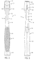
- FIG. 1 a hammer, generally indicated at 10, constructed in accordance with the present invention.
- the hammer 10 comprises a head, generally indicated at 12, a neck portion, generally indicated at 14, and a manually engageable gripping portion, generally indicated at 16.
- a rigid support structure 18 extends longitudinally with respect to the hammer 10.
- the head 12 includes a striking surface 20, an eye 22 ( Figure 4), and a pair of tapered, spaced-apart nail removing claws 24.
- a swing plane of the hammer 10 i.e., a plane, which, as viewed in Figures 2 and 3, is perpendicular to the page and extends longitudinally through the center of the hammer
- the striking surface 20 strikes an object. That is, the striking surface 20 is transverse to the swing plane of the hammer 10.
- the nail removing claws 24 are spaced apart so as to provide a V-shaped space 26 therebetween.
- the shank of a nail can be received in the V-shaped space 26 with the top of the hammer 10 facing the workpiece and the nail is removed by engaging the spaced apart claws 24 with the head of the nail and withdrawing it from the workpiece.
- the striking surface 20 is slightly convex in order to facilitate square contact during driving of nails.
- hammer head 12 shown is of the conventional type but the present invention may be applied to other types of hammers such as ballpeen hammers and hand-held sledge hammers and mauls.
- Fig. 8 illustrates a ballpeen hammer 10A constructed in accordance with the present invention.
- the ballpeen hammer 10 has a ballpeen head 12A with striking surface 20A.
- the head 12 is provided on the top longitudinal end of the rigid support structure 18.
- an impact force acts on the striking surface 20 in a direction parallel to the swing plane.
- the impact force acting on the striking surface 20 generates a vibration in the rigid support structure 18 acting in a direction parallel to the swing plane of the hammer 10.
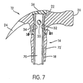
- the head 12 is mounted on the top end of the rigid support structure 18 by inserting the top end of the rigid support structure 18 into the eye 22 of the head 12.
- the front and rear interior surfaces 28, 30 of the eye 22 have arcuate, convex configurations which provide the eye 22 with maximum diameters at the upper and lower ends thereof and a minimum diameter in the mid-region thereof.
- the minimum diameter of the eye 22 between the front and rear interior surfaces 28, 30 thereof is slightly less than the width of the rigid support structure 18 between the exterior front and rear surfaces 32, 34 thereof.
- the head 12 is mounted by forcing the rigid support structure 18 into the eye 22 such that the front and rear exterior surfaces 32, 34 of the rigid support structure 18 are forcibly engaged with the front and rear interior surfaces 28, 30 of the eye 22.
- a molten epoxy resin 36 is injected into the eye 22 so as to fill the interior of the eye 22 and form a solidified mass of epoxy 36 surrounding the top end of the rigid support structure 18.
- An epoxy-receiving opening 35 provided on the rigid support structure 18 is also filled with the solidified epoxy 36 and aids in securing the rigid support structure 18 within the eye 22.
- the illustrated rigid support structure 18 is an I-beam with the front and rear exterior surfaces 32, 34 being provided on the end caps 37 and the epoxy-receiving opening 35 being formed through the web 39 extending between the end caps 37.
- the end caps of the rigid support structure 18 present convex arcuate exterior surfaces.
- the preferred configuration for the rigid support structure 18 is the illustrated I-beam.
- both the head 12 and the rigid support structure 18 are made of steel. The solid connection between the head 12 and the rigid support structure 18 allows vibrations to be created in the rigid support structure 18 when a user strikes the striking surface 20 of the head 12 against an object.
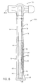
- the rigid support structure 18 has vibration-receiving portions 40 at the bottom longitudinal end thereof opposite the head 12.
- the vibration-receiving portions 40 extend generally longitudinally to the bottom end of the rigid support structure 18 and are spaced apart from one another in a direction parallel to the swing plane so as to define a resiliently deformable material-receiving space 42 therebetween.
- the resiliently deformable material-receiving space 42 is open to the bottom longitudinal end of the rigid support structure 18.
- the resiliently deformable material-receiving space 42 is formed through the web 39 of the I-beam constituting the rigid support structure 18.
- the vibration-receiving portions 40 and the space 42 defined therebetween may take a variety of configurations.
- the embodiment of Figure 6 shows that the interior surfaces 44 of the vibration-receiving portions 40 which define the space 42 are substantially straight and terminate at an arcuate surface 46. This arrangement is preferred due to its simplicity and easy of manufacturing.
- Figure 5 illustrates another example in which the vibration-receiving portions 40 have substantially straight interior surfaces 48 extending from the bottom longitudinal end and a widened portion defined by substantially straight interior surfaces 50 which are connected to one another by arcuate surface 52 and are connected to the substantially straight surfaces 48 by arcuate surfaces 54.
- the rigid support structure 18 may be provided with a second resiliently deformable material-receiving space 56.
- the second material-receiving space 56 is spaced longitudinally from the space 42 towards the head 12 and defined by a pair of substantially straight interior surfaces 58 interconnected by arcuate surfaces 60.
- the manually engageable gripping portion 16 surrounds the rigid support structure 18 and is formed from a solidified, resiliently deformable material.
- a portion of the resiliently deformable material is received within the resiliently deformable material-receiving space 42 and surrounds the vibration-receiving portions such that vibrations received by the vibration-receiving portions 40 are damped by the resiliently deformable material.
- Another portion of the resiliently deformable material is received within the second resiliently deformable material-receiving space 56.
- a portion of the vibrational energy that results when the striking surface 20 impacts a workpiece is transferred through the rigid support structure 18 to the vibration receiving portions 40, which together behave much like a tuning fork. Vibration of the portions 40 is dampened because the resiliently deformable material is received within the resiliently deformable material-receiving space 42 , thereby dissipating a significant portion of the vibrational energy transferred to the elements 50. Thus, the amount of vibration that is transmitted to the hand of the user following impact is reduced.
- the preferred method of forming the manually engageable gripping portion 16 is to injection mold molten polyvinyl chloride (PVC) around the rigid support structure 18 so as to surround the rigid support structure 18, including the vibrations-receiving portions 40, and fill in the resiliently deformable material receiving spaces 42 and 56.
- PVC polyvinyl chloride
- the intermediate portion 70 can also be provided with a plurality of additional holes therethrough to further enhance the securing of gripping portion 16 to the rigid support structure.
- the PVC contains 1 to 2% nylon in order to enhance the cosmetic appearance of the manually engageable portion 16 and has the following approximate physical properties: Tensile Strength 0.381 Kg/mm 2 [540 P.S.I.] Hardness (Shore A Durometer) 71 +/-5 Specific Gravity 1.49
- the manually engageable gripping portion 16 is molded so as to provide a slightly concave surface 62 for the user to comfortably engage with the heel of his palm. Opposite the concave surface 62 is a textured convex surface 64 to be engaged by the user's fingers.
- the textured convex surface 64 includes a plurality of arcuate indentations 65 spaced longitudinally along the surface 64. Adjacent the concave surface 62 is a concave thumbrest surface 66.
- the gripping portion 16 is wider in its mid-region and tapers inwardly towards the neck portion 14 and the butt-end portion 68.
- the butt-end portion 68 has an outwardly extending projection 69 which prevents the users hand from slipping off the end of the hammer 10 during usage.
- the neck portion 14 is located between the manually engageable gripping portion 16 and the head 12.
- the neck portion 14 includes an intermediate portion 70 of the rigid support structure 18 surrounded by rigid material 72.
- the preferred rigid material is an engineering-grade thermoplastic polyurethane used in extrusion and injection molding, such as Isoplast®.
- the rigid material 72 is injection molded around the intermediate portion 70 of the support structure 18 and when solidified provides a rigid, transparent covering for the intermediate portion 70.
- the actual appearance of the neck portion 14 is not essential to achieving the objects of the present invention, but the use of Isoplast® is preferred for cosmetic reasons.
- the use of such a structurally rigid material is desirable from a functional point of view because it protects the intermediate portion 70 of the rigid support structure 18 from being damaged during use of the hammer 10, whether such damage results from overstrikes or simply dropping the hammer 10.
Landscapes
- Engineering & Computer Science (AREA)
- Mechanical Engineering (AREA)
- Percussive Tools And Related Accessories (AREA)
- Toys (AREA)
- Golf Clubs (AREA)
Claims (13)
- Hammer (10), welcher aufweist:dadurch gekennzeichnet, dass:eine feste Stützstruktur (18), die sich in Längsrichtung in Bezug auf den Hammer (10) erstreckt, wobei die feste Stützstruktur (18) einen ersten Längsendabschnitt und einen zweiten Endabschnitt gegenüber dem ersten Längsendabschnitt hat;einen Kopf (12), der an dem ersten Längsendabschnitt der festen Stützstruktur (18) vorgesehen ist und quer hierzu angeordnet ist, wobei der Kopf (12) an einem Ende eine Schlagfläche (20) hat, wobei die Schlagfläche (20) so angeordnet ist, daß die Schlagfläche (20) einen Gegenstand trifft, wenn der Hammer (10) in Richtung auf den Gegenstand in einer Schwingebene des Hammers (10) geschwungen wird, wodurch eine Schlagkraft erzeugt wird, die auf die Schlagfläche (20) in eine Richtung parallel zur Schwingebene wirkt, wobei die Schlagkraft Vibrationen in der festen Stützstruktur (18) erzeugt, die in einer Richtung parallel zur Schwingebene wirken; undeinen manuell eingreifbaren Greifabschnitt (16), der die feste Stützstruktur (18) umgibt und eine Außenfläche hat, die so konstruiert und ausgebildet ist, daß sie von einer den Hammer (10) benutzenden Person gegriffen werden kann, wobei der Greifabschnitt (16) aus elastisch verformbarem Material gebildet ist,der zweite Endabschnitt ein Paar Vibration-aufnehmende Abschnitte (40) aufweist, die sich in Längsrichtung in eine Richtung von dem ersten Längsendabschnitt weg erstrecken und in einem Abstand voneinander enden, wobei die Vibration-aufnehmende Abschnitte (40) voneinander in einer Richtung parallel zur Schwingebene des Hammers (10) beabstandet sind; undein Abschnitt des elastisch verformbaren Materials in dem Raum (42) zwischen den Vibration-aufnehmenden Abschnitten (40) aufgenommen ist und die Vibration-aufnehmende Abschnitte (40) umgibt, so dass Vibrationen, die in eine Richtung parallel zur Schwingebene wirken und von den Vibration-aufnehmenden Abschnitten (40) aufgenommen werden, von dem elastisch verformbaren Material gedämpft werden, um hierdurch das Maß an Vibrationen, die an die Hand des Benutzers übertragen werden, zu reduzieren.
- Hammer nach Anspruch 1, wobei der Kopf (12) ein Paar sich verjüngender, beabstandeter Nagel-Entfern-Klauen (24) an einem Ende des Kopfes (12) gegenüber der Schlagfläche (20) beinhaltet.
- Hammer nach einem der Ansprüche 1 und 2, wobei der Kopf einen Kugelhammer-Kopf ( 12A) aufweist.
- Hammer nach einem der Ansprüche 1 bis 3, wobei der erste Längsendabschnitt der festen Stützstruktur (18) in ein Auge (22) eingeführt ist, das in dem Kopf (12) gebildet ist, wobei das Auge (22) eine Bohrung aufweist, die durch den Kopf (12) hindurch gebildet ist, wobei die Bohrung erste und zweite einander gegenüberliegende Innenflächen (28, 30) aufweist, die jeweils eine gebogene konvexe Konfiguration haben, so dass von einem Ende der Bohrung ausgehend zu einem gegenüberliegenden Ende davon die Innenflächen der Bohrung sich zuerst nach innen zu einem Abschnitt von minimaler transversaler Abmessung zusammen laufen und dann nach außen auseinander laufen.
- Hammer nach Anspruch 4, wobei die transversale Abmessung an dem Abschnitt der minimalen transversalen Abmessung der Bohrung etwas kleiner ist als die transversale Abmessung der festen Stützstruktur (18), so dass, wenn die feste Stützstruktur (18) unter Kraftaufwendung in das Auge (22) eingeführt wird, die vorderen und hinteren Außenflächen (32, 34) der festen Stützstruktur (18) unter Kraftaufwendung mit Abschnitten der ersten und zweiten Innenflächen (28, 30) der Bohrung in Eingriff kommen.
- Hammer nach einem der Ansprüche 4 und 5, wobei die feste Stützstruktur (18) in dem Auge (22) durch Epoxyharz (36) gesichert ist, das in das Auge (22) so eingespritzt ist, dass es das Innere der Bohrung füllt.
- Hammer nach einem der Ansprüche 1 bis 6, wobei die feste Stützstruktur (18) einen I-Balken mit einander gegenüberliegenden Endkappen (37) und einem Innensteg (39) aufweist, das sich zwischen den Endkappen (37) erstreckt.
- Hammer nach einem der Ansprüche 1 bis 7, wobei der Kopf (12, 12A) und die feste Stützstruktur (18) aus Stahl gefertigt sind.
- Hammer nach einem der Ansprüche 1 bis 8, wobei die feste Stützstruktur (18) einen zweiten elastisch verformbares Material aufnehmenden Raum (56) beinhaltet, wobei ein Abschnitt des elastisch verformbaren Materials des manuell eingreifbaren Greifabschnitts (16) in dem zweiten elastisch verformbares Material aufnehmenden Raum (56) aufgenommen ist.
- Hammer nach einem der Ansprüche 1 bis 9, wobei der manuell eingreifbare Greifabschnitt (16) aus spritzgegossenem Polyvinylchlorid gebildet ist.
- Hammer nach Anspruch 10, wobei das Polyvinylchlorid 1-2% Nylon enthält.
- Hammer nach einem der Ansprüche 1 bis 11, wobei der manuell eingreifbare Greifabschnitt (16) eine Mehrzahl von bogenförmigen Vertiefungen (65), die in Längsrichtung entlang einer Außenfläche an einer Seite davon beabstandet sind, und eine konkave Daumenauflagefläche (66), die an einer Außenfläche einer gegenüberliegenden Seite davon gebildet ist, aufweist.
- Hammer nach einem der Ansprüche 1 bis 12, wobei ein Zwischenabschnitt (70) der festen Stützstruktur (18) zwischen dem Kopf (12) und dem manuell eingreifbaren Greifabschnitt (16) von einem festen Material (72) umgeben ist, das thermoplastisches Polyurethan aufweist.
Applications Claiming Priority (3)
| Application Number | Priority Date | Filing Date | Title |
|---|---|---|---|
| US9668898P | 1998-08-14 | 1998-08-14 | |
| US96688P | 1998-08-14 | ||
| PCT/US1999/018159 WO2000009296A1 (en) | 1998-08-14 | 1999-08-11 | Vibration damped hammer |
Publications (2)
| Publication Number | Publication Date |
|---|---|
| EP1105255A1 EP1105255A1 (de) | 2001-06-13 |
| EP1105255B1 true EP1105255B1 (de) | 2003-11-19 |
Family
ID=22258591
Family Applications (1)
| Application Number | Title | Priority Date | Filing Date |
|---|---|---|---|
| EP99939726A Expired - Lifetime EP1105255B1 (de) | 1998-08-14 | 1999-08-11 | Vibrationsgedämpfter hammer |
Country Status (6)
| Country | Link |
|---|---|
| US (1) | US6202511B1 (de) |
| EP (1) | EP1105255B1 (de) |
| AU (1) | AU5396599A (de) |
| DE (1) | DE69912962T2 (de) |
| TW (1) | TW466160B (de) |
| WO (1) | WO2000009296A1 (de) |
Families Citing this family (39)
| Publication number | Priority date | Publication date | Assignee | Title |
|---|---|---|---|---|
| US6405616B1 (en) * | 2000-08-24 | 2002-06-18 | John Chen | Hammer with shock-reduction structure |
| ITMI20020010A1 (it) * | 2002-01-08 | 2003-07-08 | Top Glass Spa | Elemento ad elevata resistenza meccanica ed elevato grado di smorzamento di vibrazioni e procedimento per la sua realizzazione |
| US6945138B1 (en) | 2002-07-24 | 2005-09-20 | Kreitzer David F | Recoiling striking device |
| USD551529S1 (en) | 2002-08-07 | 2007-09-25 | Estwing Manufacturing Company | Hammer |
| WO2004014615A1 (en) * | 2002-08-07 | 2004-02-19 | Estwing Manufacturing Company | Striking tool with weight forward head |
| TW556636U (en) * | 2002-08-09 | 2003-10-01 | Chen Chang Rong | Improved shock-proof structure for hammer |
| US6848341B2 (en) | 2002-10-16 | 2005-02-01 | Artistic View, Inc. | Rock hammer |
| US6892468B2 (en) * | 2003-04-17 | 2005-05-17 | The Stanley Works | Retractable rule assembly with improved blade opening |
| US7770262B2 (en) * | 2003-05-19 | 2010-08-10 | Robert Bosch Tool Corporation | Cushion grip handle |
| USD549066S1 (en) | 2004-05-03 | 2007-08-21 | Estwing Manufacturing Company | Hammer |
| USD521342S1 (en) | 2004-05-03 | 2006-05-23 | Estwing Manufacturing Company | Hammer |
| US20060021474A1 (en) * | 2004-07-28 | 2006-02-02 | Michael Burgess | Double headed striking tool |
| US7168338B2 (en) * | 2004-11-29 | 2007-01-30 | Snap-On Incorporated | Dead blow hammer with composite holder |
| CA2506986A1 (en) * | 2005-05-10 | 2006-11-10 | Garant Gp | A shaft for tools, and tool and a method of fabrication thereof |
| US8499665B2 (en) | 2006-08-30 | 2013-08-06 | Stanley Black & Decker, Inc. | Torsion control hammer grip |
| US20090271929A1 (en) * | 2008-05-05 | 2009-11-05 | Robert Adams | Multi-function tool for demolition |
| USD600523S1 (en) | 2008-05-06 | 2009-09-22 | Robert Adams | Hammer |
| USD607296S1 (en) | 2009-01-14 | 2010-01-05 | The Stanley Works | Hammer head |
| US8047099B2 (en) | 2009-02-09 | 2011-11-01 | Stanley Black & Decker, Inc. | Large strike face hammer |
| DK2380706T3 (da) * | 2010-04-24 | 2013-02-18 | Gedore Werkzeugfabrik Gmbh & Co Kg | Hammer, især forhammer, og fremgangsmåde til fremstilling af en sådan hammer |
| FR2969025B1 (fr) * | 2010-12-21 | 2013-01-04 | Fiskars France Sas | Outil de frappe a main permettant de reduire les vibrations, et son procede de fabrication |
| US10974423B2 (en) * | 2011-01-13 | 2021-04-13 | The Ames Companies, Inc. | Wood handle with overmold and method of manufacture |
| CN103442857B (zh) * | 2011-03-24 | 2017-07-28 | 胡斯华纳有限公司 | 用于手工工具的手柄保护件 |
| US8894044B2 (en) | 2012-08-17 | 2014-11-25 | S.C. Johnson & Son, Inc. | Dispenser |
| US9204625B2 (en) | 2012-08-17 | 2015-12-08 | S.C. Johnson & Son, Inc. | Dispenser |
| US9649400B2 (en) | 2012-08-17 | 2017-05-16 | S.C. Johnson & Son, Inc. | Method and system for dispensing a composition |
| USD716628S1 (en) | 2012-10-04 | 2014-11-04 | Estwing Manufacturing Company, Inc. | Hammer |
| USD704813S1 (en) | 2013-06-17 | 2014-05-13 | S. C. Johnson & Son, Inc. | Dispenser |
| USD752938S1 (en) | 2014-03-14 | 2016-04-05 | Estwing Manufacturing Company, Inc. | Hammer |
| EP3169486A1 (de) | 2014-07-14 | 2017-05-24 | Fiskars Brands, Inc. | Vibrationsreduzierungsmechanismus für ein schlagwerkzeug |
| US9259829B1 (en) * | 2014-08-25 | 2016-02-16 | Cougar Holdings, Llc | Roofing and nail removal hammer |
| US10377556B2 (en) | 2015-02-04 | 2019-08-13 | S.C. Johnson & Son, Inc. | Retaining apparatus |
| US10071471B2 (en) * | 2015-08-17 | 2018-09-11 | Mayhew Steel Products, Inc. | Pry bar handle |
| US9731413B1 (en) * | 2016-02-04 | 2017-08-15 | M.J. Huner LLC | Overstrike protector |
| US10583550B2 (en) * | 2017-11-02 | 2020-03-10 | Stanley Black & Decker, Inc. | Grip component for a hand tool |
| US11110585B2 (en) * | 2017-11-02 | 2021-09-07 | Stanley Black & Decker, Inc. | Grip component for a hand tool |
| WO2020247437A1 (en) * | 2019-06-07 | 2020-12-10 | Rvp Services, Llc D/B/A Thor Specialty Tools | Orifice plate removal tool |
| DE102019122723B4 (de) * | 2019-08-23 | 2024-02-01 | Fritsch Gmbh | Partikelgrößenmessgerät |
| US11660738B2 (en) | 2020-12-09 | 2023-05-30 | Stanley Black & Decker, Inc. | Ergonomic grip for striking tool |
Citations (1)
| Publication number | Priority date | Publication date | Assignee | Title |
|---|---|---|---|---|
| US3792725A (en) * | 1972-11-17 | 1974-02-19 | Stanley Works | Hammer |
Family Cites Families (21)
| Publication number | Priority date | Publication date | Assignee | Title |
|---|---|---|---|---|
| US1707787A (en) * | 1929-04-02 | A cospokation | ||
| US1311820A (en) | 1919-07-29 | Metallic building structure | ||
| US2850331A (en) | 1954-09-13 | 1958-09-02 | Fayette R Plumb Inc | Handle connection for percussive tool |
| US3078969A (en) | 1959-06-15 | 1963-02-26 | Lord Mfg Co | Damped beam |
| US3283464A (en) | 1960-05-10 | 1966-11-08 | Litzka Franz | Honeycomb girders and method for making same |
| US3320985A (en) * | 1965-10-07 | 1967-05-23 | Stanley Works | Hammer with solid steel handle |
| ZA784458B (en) | 1978-08-07 | 1979-12-27 | Modern Inventions Ltd | Handle |
| US4425980A (en) | 1981-12-14 | 1984-01-17 | The Boeing Company | Beam dampers for damping the vibrations of the skin of reinforced structures |
| GB2135625A (en) | 1983-01-31 | 1984-09-05 | Supersafe Fibreglass Tool Hand | Tool handle |
| US4633741A (en) * | 1983-10-21 | 1987-01-06 | Yang Tai Her | Hammering tool with flexible handle |
| US4697481A (en) | 1985-02-21 | 1987-10-06 | Maeda Shell Service Co., Ltd. | Integrally molded hammer with separated head and handle cores |
| ZA851343B (en) * | 1985-02-22 | 1985-10-30 | Patrick Arthur Lamont | Hammer and handle |
| JPS62156482U (de) * | 1986-03-25 | 1987-10-05 | ||
| US4721021A (en) | 1986-09-10 | 1988-01-26 | Kusznir Phillip S | Handle structure |
| US5308675A (en) | 1992-09-15 | 1994-05-03 | The United States Of America As Represented By The Secretary Of The Navy | Flexible high damping structure |
| US5280739A (en) * | 1992-12-03 | 1994-01-25 | Liou Mou T | Handle of a hammer having a shock absorbing configuration |
| US5408902A (en) | 1994-03-10 | 1995-04-25 | Burnett John A | Composite percussive tool |
| US5588343A (en) * | 1994-09-15 | 1996-12-31 | The Stanley Works | Handle with improved grip assembly for hammers and the like and method of making same |
| US5657674A (en) * | 1996-04-18 | 1997-08-19 | Burnett; John A. | Composite Percussive tool |
| US5896788A (en) * | 1997-10-09 | 1999-04-27 | The Stanley Works | Hammer with improved handle interlock and method of making same |
| US5911795A (en) * | 1997-10-15 | 1999-06-15 | The Stanley Works | Hammer with vibration damper and method of making same |
-
1999
- 1999-08-10 US US09/371,586 patent/US6202511B1/en not_active Expired - Lifetime
- 1999-08-11 EP EP99939726A patent/EP1105255B1/de not_active Expired - Lifetime
- 1999-08-11 AU AU53965/99A patent/AU5396599A/en not_active Abandoned
- 1999-08-11 DE DE69912962T patent/DE69912962T2/de not_active Expired - Lifetime
- 1999-08-11 WO PCT/US1999/018159 patent/WO2000009296A1/en not_active Ceased
-
2000
- 2000-01-18 TW TW088113878A patent/TW466160B/zh not_active IP Right Cessation
Patent Citations (1)
| Publication number | Priority date | Publication date | Assignee | Title |
|---|---|---|---|---|
| US3792725A (en) * | 1972-11-17 | 1974-02-19 | Stanley Works | Hammer |
Also Published As
| Publication number | Publication date |
|---|---|
| DE69912962D1 (de) | 2003-12-24 |
| DE69912962T2 (de) | 2004-09-02 |
| US6202511B1 (en) | 2001-03-20 |
| AU5396599A (en) | 2000-03-06 |
| EP1105255A1 (de) | 2001-06-13 |
| WO2000009296A1 (en) | 2000-02-24 |
| TW466160B (en) | 2001-12-01 |
Similar Documents
| Publication | Publication Date | Title |
|---|---|---|
| EP1105255B1 (de) | Vibrationsgedämpfter hammer | |
| US6370986B1 (en) | Impact cushioning tool handle | |
| US4738166A (en) | Helve of a hammer | |
| CA2307507C (en) | Shock absorption system for a striking tool | |
| US6530098B1 (en) | Multiple tool device | |
| KR960005139Y1 (ko) | 금속부재가 내장된 플라스틱 렌치 | |
| US6763747B1 (en) | Shock absorbing hammer and handle assembly | |
| US7874231B2 (en) | Striking tool | |
| EP1894681B1 (de) | Manuell betreibbares Schlagwerkzeug und Verfahren zur Herstellung eines manuell betreibbaren Schlagwerkzeugs | |
| CA2773934C (en) | Hammer head and handle assembly | |
| CN107073699A (zh) | 用于打击工具的减振机构 | |
| US5490437A (en) | Hammer | |
| CA2089909C (en) | Vibration damping device for hammers | |
| US4172483A (en) | Percussion head tool | |
| US3208724A (en) | Carpenter's claw hammer with vibration dampening means | |
| US7448299B1 (en) | Hand tool with vibration-damping sleeve | |
| US20050178243A1 (en) | Ergonomic tool handle and related hammer system | |
| US20060005667A1 (en) | Vibration-damping hammer | |
| ES2259716T3 (es) | Herramienta de impacto con cabezal antiesquirlas. | |
| US6386071B1 (en) | Recoil reducing apparatus for striking tools | |
| KR200415829Y1 (ko) | 망치 | |
| CN222405544U (zh) | 一种带有减震功能的锤子 | |
| CA2254184C (en) | Golf club with titanium head and plastic hosel | |
| KR200347466Y1 (ko) | 완충기능이 구비되는 망치 | |
| KR101490037B1 (ko) | 목 보호기능을 가진 해머 |
Legal Events
| Date | Code | Title | Description |
|---|---|---|---|
| PUAI | Public reference made under article 153(3) epc to a published international application that has entered the european phase |
Free format text: ORIGINAL CODE: 0009012 |
|
| 17P | Request for examination filed |
Effective date: 20010309 |
|
| AK | Designated contracting states |
Kind code of ref document: A1 Designated state(s): AT BE CH CY DE DK ES FI FR GB GR IE IT LI LU MC NL PT SE |
|
| AX | Request for extension of the european patent |
Free format text: AL;LT;LV;MK;RO;SI |
|
| GRAH | Despatch of communication of intention to grant a patent |
Free format text: ORIGINAL CODE: EPIDOS IGRA |
|
| GRAS | Grant fee paid |
Free format text: ORIGINAL CODE: EPIDOSNIGR3 |
|
| GRAA | (expected) grant |
Free format text: ORIGINAL CODE: 0009210 |
|
| AK | Designated contracting states |
Kind code of ref document: B1 Designated state(s): DE FR GB IT NL |
|
| PG25 | Lapsed in a contracting state [announced via postgrant information from national office to epo] |
Ref country code: NL Free format text: LAPSE BECAUSE OF FAILURE TO SUBMIT A TRANSLATION OF THE DESCRIPTION OR TO PAY THE FEE WITHIN THE PRESCRIBED TIME-LIMIT Effective date: 20031119 Ref country code: IT Free format text: LAPSE BECAUSE OF FAILURE TO SUBMIT A TRANSLATION OF THE DESCRIPTION OR TO PAY THE FEE WITHIN THE PRESCRIBED TIME-LIMIT;WARNING: LAPSES OF ITALIAN PATENTS WITH EFFECTIVE DATE BEFORE 2007 MAY HAVE OCCURRED AT ANY TIME BEFORE 2007. THE CORRECT EFFECTIVE DATE MAY BE DIFFERENT FROM THE ONE RECORDED. Effective date: 20031119 |
|
| REG | Reference to a national code |
Ref country code: GB Ref legal event code: FG4D |
|
| REF | Corresponds to: |
Ref document number: 69912962 Country of ref document: DE Date of ref document: 20031224 Kind code of ref document: P |
|
| REG | Reference to a national code |
Ref country code: IE Ref legal event code: FG4D |
|
| LTIE | Lt: invalidation of european patent or patent extension |
Effective date: 20031119 |
|
| NLV1 | Nl: lapsed or annulled due to failure to fulfill the requirements of art. 29p and 29m of the patents act | ||
| ET | Fr: translation filed | ||
| PLBE | No opposition filed within time limit |
Free format text: ORIGINAL CODE: 0009261 |
|
| STAA | Information on the status of an ep patent application or granted ep patent |
Free format text: STATUS: NO OPPOSITION FILED WITHIN TIME LIMIT |
|
| 26N | No opposition filed |
Effective date: 20040820 |
|
| REG | Reference to a national code |
Ref country code: IE Ref legal event code: MM4A |
|
| PGFP | Annual fee paid to national office [announced via postgrant information from national office to epo] |
Ref country code: GB Payment date: 20120828 Year of fee payment: 14 |
|
| PGFP | Annual fee paid to national office [announced via postgrant information from national office to epo] |
Ref country code: FR Payment date: 20120830 Year of fee payment: 14 Ref country code: DE Payment date: 20120829 Year of fee payment: 14 |
|
| GBPC | Gb: european patent ceased through non-payment of renewal fee |
Effective date: 20130811 |
|
| PG25 | Lapsed in a contracting state [announced via postgrant information from national office to epo] |
Ref country code: DE Free format text: LAPSE BECAUSE OF NON-PAYMENT OF DUE FEES Effective date: 20140301 |
|
| REG | Reference to a national code |
Ref country code: DE Ref legal event code: R119 Ref document number: 69912962 Country of ref document: DE Effective date: 20140301 |
|
| REG | Reference to a national code |
Ref country code: FR Ref legal event code: ST Effective date: 20140430 |
|
| PG25 | Lapsed in a contracting state [announced via postgrant information from national office to epo] |
Ref country code: GB Free format text: LAPSE BECAUSE OF NON-PAYMENT OF DUE FEES Effective date: 20130811 |
|
| PG25 | Lapsed in a contracting state [announced via postgrant information from national office to epo] |
Ref country code: FR Free format text: LAPSE BECAUSE OF NON-PAYMENT OF DUE FEES Effective date: 20130902 |