EP1105609B1 - Dispositif de verrouillage de porte encastre dans le sol - Google Patents
Dispositif de verrouillage de porte encastre dans le sol Download PDFInfo
- Publication number
- EP1105609B1 EP1105609B1 EP99941572A EP99941572A EP1105609B1 EP 1105609 B1 EP1105609 B1 EP 1105609B1 EP 99941572 A EP99941572 A EP 99941572A EP 99941572 A EP99941572 A EP 99941572A EP 1105609 B1 EP1105609 B1 EP 1105609B1
- Authority
- EP
- European Patent Office
- Prior art keywords
- pivot pin
- floor
- shank
- locking device
- conical
- Prior art date
- Legal status (The legal status is an assumption and is not a legal conclusion. Google has not performed a legal analysis and makes no representation as to the accuracy of the status listed.)
- Expired - Lifetime
Links
- 239000011521 glass Substances 0.000 claims abstract description 4
- 230000002093 peripheral effect Effects 0.000 claims description 15
- 238000006073 displacement reaction Methods 0.000 claims 2
- 230000008878 coupling Effects 0.000 description 2
- 238000010168 coupling process Methods 0.000 description 2
- 238000005859 coupling reaction Methods 0.000 description 2
- 230000004075 alteration Effects 0.000 description 1
- 239000012634 fragment Substances 0.000 description 1
- 238000009434 installation Methods 0.000 description 1
Images


Classifications
-
- E—FIXED CONSTRUCTIONS
- E05—LOCKS; KEYS; WINDOW OR DOOR FITTINGS; SAFES
- E05F—DEVICES FOR MOVING WINGS INTO OPEN OR CLOSED POSITION; CHECKS FOR WINGS; WING FITTINGS NOT OTHERWISE PROVIDED FOR, CONCERNED WITH THE FUNCTIONING OF THE WING
- E05F3/00—Closers or openers with braking devices, e.g. checks; Construction of pneumatic or liquid braking devices
- E05F3/22—Additional arrangements for closers, e.g. for holding the wing in opened or other position
- E05F3/225—Additional arrangements for closers, e.g. for holding the wing in opened or other position mounted at the bottom of wings, e.g. details related to seals, covers, connections to the wings, embedding in the floor
-
- E—FIXED CONSTRUCTIONS
- E05—LOCKS; KEYS; WINDOW OR DOOR FITTINGS; SAFES
- E05F—DEVICES FOR MOVING WINGS INTO OPEN OR CLOSED POSITION; CHECKS FOR WINGS; WING FITTINGS NOT OTHERWISE PROVIDED FOR, CONCERNED WITH THE FUNCTIONING OF THE WING
- E05F3/00—Closers or openers with braking devices, e.g. checks; Construction of pneumatic or liquid braking devices
- E05F3/04—Closers or openers with braking devices, e.g. checks; Construction of pneumatic or liquid braking devices with liquid piston brakes
-
- E—FIXED CONSTRUCTIONS
- E05—LOCKS; KEYS; WINDOW OR DOOR FITTINGS; SAFES
- E05Y—INDEXING SCHEME ASSOCIATED WITH SUBCLASSES E05D AND E05F, RELATING TO CONSTRUCTION ELEMENTS, ELECTRIC CONTROL, POWER SUPPLY, POWER SIGNAL OR TRANSMISSION, USER INTERFACES, MOUNTING OR COUPLING, DETAILS, ACCESSORIES, AUXILIARY OPERATIONS NOT OTHERWISE PROVIDED FOR, APPLICATION THEREOF
- E05Y2201/00—Constructional elements; Accessories therefor
- E05Y2201/60—Suspension or transmission members; Accessories therefor
- E05Y2201/622—Suspension or transmission members elements
- E05Y2201/706—Shafts
-
- E—FIXED CONSTRUCTIONS
- E05—LOCKS; KEYS; WINDOW OR DOOR FITTINGS; SAFES
- E05Y—INDEXING SCHEME ASSOCIATED WITH SUBCLASSES E05D AND E05F, RELATING TO CONSTRUCTION ELEMENTS, ELECTRIC CONTROL, POWER SUPPLY, POWER SIGNAL OR TRANSMISSION, USER INTERFACES, MOUNTING OR COUPLING, DETAILS, ACCESSORIES, AUXILIARY OPERATIONS NOT OTHERWISE PROVIDED FOR, APPLICATION THEREOF
- E05Y2600/00—Mounting or coupling arrangements for elements provided for in this subclass
- E05Y2600/50—Mounting methods; Positioning
- E05Y2600/504—Expansion
-
- E—FIXED CONSTRUCTIONS
- E05—LOCKS; KEYS; WINDOW OR DOOR FITTINGS; SAFES
- E05Y—INDEXING SCHEME ASSOCIATED WITH SUBCLASSES E05D AND E05F, RELATING TO CONSTRUCTION ELEMENTS, ELECTRIC CONTROL, POWER SUPPLY, POWER SIGNAL OR TRANSMISSION, USER INTERFACES, MOUNTING OR COUPLING, DETAILS, ACCESSORIES, AUXILIARY OPERATIONS NOT OTHERWISE PROVIDED FOR, APPLICATION THEREOF
- E05Y2900/00—Application of doors, windows, wings or fittings thereof
- E05Y2900/10—Application of doors, windows, wings or fittings thereof for buildings or parts thereof
- E05Y2900/13—Type of wing
- E05Y2900/132—Doors
Definitions
- the present invention relates to a floor-embedded locking device for a door, in particular for an all-glass door, comprising a pivot pin device.
- the pivot axis of a door such as an all-glass door may comprise a device wherein a pivot pin of a floor-embedded locking device is non-rotationally received so that said pivot pin is pivoted together with a pivotally supported receiving bush when the door is pivoted, with said receiving bush being surrounded by a cam plate which is engaged by a spring-mounted, longitudinally displaceable piston.
- the pivot pin is manufactured with such a length that a sufficiently long portion of it protrudes upwardly from the floor-embedded locking device, and is then installed in the floor-embedded locking device.
- an adjustable coupler of a design is known that permits for adjustably coupling a floor embedded door closer to a pivot or butt hinge mounted door while permitting access to the door closer without unhinging the door.
- a closer arm is provided which is adapted for door mounting and also connection to the projecting pivot pin portion of the door closer.
- the closer arm has an enlarged head receiving the slotted projecting pivot pin portion which has a hexagonal cross-section and includes a tapered threaded bore receiving an expanding screw to expand the slotted pivot pin portion into tight frictional contact with the closer arm head.
- Pivot pins of floor-embedded locking devices may comprise, for example, as known from DE 22 18 498 A1, showing the features according to the preamble portion of claim 1, adjacent to and below its annular collar a shank portion formed as a truncated pyramid which engages into a receiving bush having a matching internal shape.
- this design enables the pivot pin to be non-rotationally received in the receiving bush, the precise dimensions of the particular application need to be known beforehand, since the length of the pivot pin portion protruding from the floor-embedded locking device may not be adjusted at the assembly site. As a result, it is often necessary to provide a choice of pivot pins with different shank lengths at the assembly site.
- the pivot pin must be replaced by another one having a different length when the distance between the upper edge of the floor-embedded locking device and the lower edge of the door is changed lateron, for example due to the provision of another floor covering.
- a pivot device for a floor-embedded locking device is known from DE 30 33 363 A1, with the pivot pin being axially fixed at a seat portion by means of screws and coupling members so that it is non-rotationally supported.
- the pivot pin comprises a plurality of notches extending transversely to its longitudinal direction, at which notches the pivot pin may be cut to the required length.
- it is also necessary to provide pivot pins with sufficiently long shanks at the assembly site, which are then assembled at the required length. If there is a change lateron in the dimensions of the assembly site, for example an alteration of the floor height, a new pivot pin which has the required new length has to be provided.
- the floor-embedded door locking device is provided with a pivot device comprising a pivot pin with an annular collar and a non-circular shank formed adjacent to said collar, said shank having a uniform cross-section along its length, and a rotatably supported receiving bush whose shape matches that of the shank and wherein the pivot pin is received in a non-rotational and axially displaceable manner.
- the shank is formed as a sleeve comprising a slotted expansion portion which is engaged by a threaded bolt extending in an axial hole of the pivot pin, by means of which threaded bolt the expansion portion may be radially expanded so that it is clampingly locked in the receiving bush.
- the present invention enables the shank of the pivot pin to be inserted into the receiving bush by a length required by the dimensional features of the particular application, i.e. so that the pivot pin protrudes from the floor-embedded locking device by such a length that the respective door may be received thereon as required.
- the threaded bolt is threaded into the axial hole
- the expansion portion of the shank which is formed by slots provided in the shank, is radially expanded so that it is clamp-fitted in the receiving bush.
- a particular advantage of the device according to the present invention consists in the fact that the pivot pin may be axially displaced in the receiving bush by removing or unscrewing the threaded bolt from the axial hole in the shank.
- the pivot pin merely has to be unlocked from its present clamping position, and clamp-fitted anew at the newly required position in the receiving bush.
- one or more plain washers, rings or the like may be placed between the annular collar of the pivot pin and the receiving bush, which may also be easily removed if no longer required.
- the pivot pin is not only held by means of a clamping fit, but in addition its annular collar is positively supported on the washer placed on the receiving bush and under the annular collar.
- the expansion portion of the shank extends from the free end of the shank to the centre thereof as seen in the longitudinal direction.
- the expansion portion may also extend to a position close to the annular collar of the pivot pin, or it may extend from the longitudinal centre of the shank in both directions towards the ends thereof, terminating at a distance from the two ends of the shank so that it is formed approximately in the central third of the length of the shank.
- the axial hole of the pivot pin is provided with an internal thread as well as a conical countersinking that is formed in the expansion portion extending from the free end of the shank and tapers towards the annular collar.
- the external thread of the threaded bolt engages the internal thread of the axial hole, and the threaded bolt comprises a conical head portion at its free end which abuts against the inner peripheral wall of the conical countersinking.
- the axial hole of the pivot pin is formed as a cylindrical counterbore within the pivot pin and has a shoulder formed adjacent to the bottom of the bore.
- the counterbore is adjoined by a portion of the hole which is smaller in diameter than the counterbore and which terminates, within the expansion portion extending from the free end of the shank, in a conical countersinking tapering towards the annular collar.
- the threaded bolt according to this embodiment is designed as a head screw which has its head supported on said shoulder at the bottom of the bore, and which has a conical locknut screwed onto its thread, said locknut abutting against the inner peripheral wall of the conical countersinking.
- the locknut When the threaded bolt is being rotated, the locknut abutting against the peripheral wall of the conical counterbore is moved upwardly towards the screw head so that it causes the expansion portion of the shank to expand.
- the conical surfaces of the locknut and the counterbore may be designed such that the locknut is prevented from rotating together with the threaded bolt when the latter is being rotated.
- the axial bore of the pivot pin comprises a threaded portion and, within the expansion portion, a conical portion which tapers towards the end of the shank.
- the threaded bolt is threaded into the threaded portion and abuts against the inner peripheral wall of the conical portion.
- the expansion portion, and thus the conical portion tapering towards the end of the shank may be provided such that they extend from the approximate centre in the longitudinal direction of the shank to the free end thereof.
- the expansion portion comprising the conical portion tapering towards the end of the shank may also be formed in the central third of the length of the shank so that the shank is not expanded at its free end but at its centre, resulting in a convex shape.
- the threaded portion is formed at least partially along the conical portion, with the threaded bolt being conical as well.
- the conically formed threaded bolt is threaded into the at least partly threaded conical portion, it abuts against the inner peripheral wall of the conical portion and causes the latter to expand.
- the threaded bolt comprises a tool engaging recess at its end facing the end of the pivot pin, which may be formed as a slot, a cross recess, a hexagon socket, a square socket, or an internal serration profile.
- the threaded bolt may, for example, be provided with a square journal at its free end facing the free end of the pivot pin, which may be engaged by a tool having a square socket so that the threaded bolt may be operated.
- the shank of the pivot pin has a hexagonal outer shape
- the receiving bush has a hexagonal inner shape.
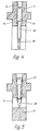
- Fig. 1 shows an exploded view of a pivot device 1 of a floor-embedded locking device for a door, with body 17 of floor-embedded locking device being shown as a fragment only.
- the pivot device 1 comprises a pivot pin 2 having a pivot pin portion 4 which is formed by two opposing plane surfaces and designed to engage into the door device.
- Pivot pin portion 4 is adjoined by an annular collar 5 which is adjoined by a hexagonal shank 6.
- An expansion portion which in this embodiment comprises six slots 7 that are each formed in one of the six peripheral surfaces of the hexagon, extends from the free end of the shank 6 to approximately the centre thereof as seen in the longitudinal direction.
- the receiving bush 3 which is pivotally supported (not shown) in the floor-embedded locking device 17 also comprises a hexagonal inner shape.
- An axial hole 8 extends through the pivot pin 2 and is engaged by the threaded bolt (not shown) by means of which the expansion portion may be expanded.
- Two plain washers 9 are placed between the pivot pin 2 and the receiving bush 3 so that they rest on the end face of the receiving bush 3.
- the annular collar 5 of the pivot pin 2 is supported on the upper washer 9. The heigth of protrusion of the pivot pin 2 from the floor-embedded locking device 17 may be adjusted by means of the washers 9.
- Shank 6, which is axially displaceable in the receiving bush 3, is inserted into the receiving bush 3 with the washers 9 placed therebetween so that the mounting height of the pivot pin 2 is adjusted in accordance with the dimensional characteristics of the particular application. Then the threaded bolt is threaded into the axial hole 8 so that the expansion portion is expanded, causing the pivot pin 2 to be clamp-fitted in the receiving bush 3.
- Fig. 2 shows the cross-sectional view of a pivot device 1 of a floor-embedded door locking device, comprising a receiving bush 3 wherein a pivot pin 2 is non-rotationally received.
- the upper portion 4 of the pivot pin which is to be received by a door device, is adjoined by an annular collar 5 which is in turn adjoined by a shank 6 of the pivot pin 2.
- the axial hole 8 of this embodiment comprises a thread which extends through the pivot pin 2.
- a conical countersinking 10 which tapers towards the annular collar 5 is provided in the expansion portion formed by slots 7 and extending from the free end of shank 6 to approximately the longitudinal centre thereof.
- a threaded bolt 11 is threaded into said axial hole 8, with the conical head portion of the threaded bolt 11 abutting against the inner peripheral wall of the conical countersinking 10.
- the end of the threaded bolt 11 which is remote from the conical head portion is formed with a tool engaging recess in the shape of a hexagon socket.
- the pivot pin 2 may be clamp-fitted in the receiving bush 3 by threading the threaded bolt 11 into the axial hole 8 so that the conical head of the threaded bolt 11 is moved upwardly within the conical countersinking 10 and thus causes the free end of the shank 6 to expand.
- the axial hole 8 comprises a cylindrical counterbore 12 in the upper portion of the pivot pin, with a shoulder being formed at the bottom 13 of the bore.
- the counterbore 12 is adjoined by a hole portion which is smaller in diameter than the counterbore 12 and, in this embodiment, extends to the conical countersinking 10.
- the threaded bolt 11 is formed as a hexagon socket screw whose head is supported on the shoulder at the bottom 13 of the bore, and has a conical locknut 14 threaded onto its free end which abuts against the inner peripheral wall of the countersinking 10. When the threaded bolt 11 is screwed into the hole, the locknut 14, which abuts against the peripheral wall, is moved upwardly so that it expands the free end of the shaft 6.
- the locknut 14 comprises a protruding pin 16 at its lateral surface which engages into one of the slots 7 so that the locknut 14 is fixed against rotation at the conical surface of the countersinking 10.
- the axial bore 8 of the pivot pin 2 comprises a threaded portion which substantially extends from the pivot pin to the expansion portion in the shank 6.
- the threaded portion is adjoined by a hole portion 17 which is smaller in diameter than the threaded portion and extends approximately across the two upper thirds of the length of shank 6. It is adjoined by a conical portion 15 which tapers towards the free end of the shank 6.
- the threaded bolt 11 comprises a cylindrical extension in the form of a journal 18 whose free end abuts against the inner peripheral wall of the conical portion 15, with the diameter of the journal 18 being smaller than that of the threaded bolt 11.
- FIG. 5 A further embodiment of the present invention is shown in Fig. 5, wherein the expansion portion with the slots 7 is provided approximately in the central third of the length of the shank rather than at the free end of the shank 6.
- the axial hole 8 comprises a cylindrical counterbore which extends to the expansion portion and is adjoined by the conically tapering portion 15 formed in the expansion portion.
- the conical portion is at least partially formed with a thread
- the threaded bolt 11 also has a conical shape.
Landscapes
- Hinges (AREA)
- Lock And Its Accessories (AREA)
- Springs (AREA)
- Elevator Door Apparatuses (AREA)
Claims (9)
- Dispositif de blocage, encastré dans le sol, pour une porte et en particulier pour une porte tout en verre, comprenant une douille de réception (3), qui est logée de manière à pouvoir tourner à l'intérieur du corps (17), encastré dans le sol, du dispositif de blocage, et une broche formant pivot (2), qui inclut au niveau de son extrémité libre, une partie saillante (4), de broche formant pivot qui fait saillie vers le haut à partir du corps (17), encastré dans le sol, du dispositif de blocage, de manière à coopérer avec la porte, un collet annulaire (5) situé en position adjacente à et au-dessous de la partie (4) de broche formant pivot, et une tige non circulaire (6) située en position adjacente à et au-dessous dudit collet (5), laquelle tige (6) est logée dans la douille de réception (3) sans possibilité de rotation et est fixée dans la douille de réception (3) au moyen d'un boulon (11) qui s'étend dans un trou axial (8) de la broche formant pivot (2), le trou axial (8) traversant ladite partie saillante (4) de ladite broche formant pivot et pénétrant dans la tige (6) de la broche formant pivot, caractérisé en ce que la tige (6) de la broche formant pivot (2) est déplaçable axialement dans ladite douille de réception (3) et est agencée sous la forme d'un manchon comprenant une partie d'expansion fendue pouvant être dilatée radialement au moyen d'un ajustement du boulon (11), ce qui permet de fixer par serrage la tige de la broche formant pivot (2) dans ses positions de déplacement dans la douille de réception (3) de sorte que la hauteur de la partie saillante (4) de broche formant pivot au-dessus du corps (17), encastré dans le sol, du dispositif de blocage est réglée au moyen dudit déplacement de la tige dans la douille de réception (3).
- Dispositif de blocage encastré dans le sol selon la revendication 1, comportant au moins une rondelle plate (9), disposée entre le collet annulaire (5) et la douille de réception (3).
- Dispositif de blocage encastré dans le sol selon la revendication 1 ou la revendication 2, dans lequel la partie d'expansion de la tige (6) s'étend à partir de l'extrémité libre de cette dernière.
- Dispositif de blocage encastré dans le sol selon l'une quelconque des revendications 1 à 3, dans lequel le trou axial (8) de la broche formant pivot (2) comprend un taraudage et, dans la partie d'expansion, il est prévu un logement conique (10), qui se rétrécit en direction du collet annulaire (5), le filetage extérieur du boulon (11) engrenant avec le taraudage du trou axial (8), et l'extrémité libre du boulon (11) comprenant une partie de tête conique qui est en butée contre la paroi périphérique intérieure du logement conique (10).
- Dispositif de blocage encastré dans le sol selon l'une quelconque des revendications 1 à 3, dans lequel le trou axial (8) de la broche formant pivot (2) est agencé sous la forme d'un contre-perçage cylindrique (12) à l'intérieur de la broche formant pivot (2), ledit contre-perçage (12) possédant un épaulement formé dans un fond (13) du trou et étant réuni par une partie du trou, qui a un diamètre inférieur au contre-perçage (12) et qui, dans la partie d'expansion, se termine au niveau d'un logement conique (10) qui se rétrécit en direction du collet annulaire (5), le boulon (11) étant agencé sous la forme d'une vis à tête, dont la tête est supportée par ledit épaulement et sur le filetage de laquelle est vissé un écrou de blocage conique (14) qui est en butée contre la paroi périphérique intérieure du logement conique (10).
- Dispositif de blocage encastré dans le sol selon l'une quelconque des revendications 1 à 3, dans lequel le trou axial (3) de la broche formant pivot (2) comprend une partie filetée et, dans la partie d'expansion, une partie conique (15) qui se rétrécit avec une forme conique en direction de l'extrémité de la tige, le boulon (11) étant vissé dans la partie filetée et étant en butée contre la paroi périphérique intérieure de la partie conique (15).
- Dispositif de blocage encastré dans le sol selon la revendication 6, dans lequel la partie filetée est formée au moins en partie le long de la partie conique (15) et le boulon (11) possède une forme conique.
- Dispositif de blocage encastré dans le sol selon l'une quelconque des revendications 1 à 7, dans lequel le boulon (11) comprend un renfoncement d'engagement d'un outil, agencé en forme de fente, de renfoncement en croix, de douille hexagonale, de douille carrée ou de profil à dentelure intérieure.
- Dispositif de blocage encastré dans le sol selon l'une quelconque des revendications 1 à 8, dans lequel la tige (5) de la broche formant pivot (2) possède une forme extérieure hexagonale, et la douille de réception (3) possède une forme intérieure hexagonale adaptée.
Applications Claiming Priority (3)
| Application Number | Priority Date | Filing Date | Title |
|---|---|---|---|
| DE29814354U | 1998-08-10 | ||
| DE29814354U DE29814354U1 (de) | 1998-08-10 | 1998-08-10 | Bodenschließvorrichtung für eine Tür |
| PCT/EP1999/005835 WO2000009845A1 (fr) | 1998-08-10 | 1999-08-10 | Dispositif de verrouillage de porte encastre dans le sol |
Publications (2)
| Publication Number | Publication Date |
|---|---|
| EP1105609A1 EP1105609A1 (fr) | 2001-06-13 |
| EP1105609B1 true EP1105609B1 (fr) | 2003-10-29 |
Family
ID=8061122
Family Applications (1)
| Application Number | Title | Priority Date | Filing Date |
|---|---|---|---|
| EP99941572A Expired - Lifetime EP1105609B1 (fr) | 1998-08-10 | 1999-08-10 | Dispositif de verrouillage de porte encastre dans le sol |
Country Status (5)
| Country | Link |
|---|---|
| EP (1) | EP1105609B1 (fr) |
| AT (1) | ATE253165T1 (fr) |
| AU (1) | AU5513799A (fr) |
| DE (2) | DE29814354U1 (fr) |
| WO (1) | WO2000009845A1 (fr) |
Families Citing this family (3)
| Publication number | Priority date | Publication date | Assignee | Title |
|---|---|---|---|---|
| DE102005029623B4 (de) * | 2005-06-23 | 2008-09-18 | Geze Gmbh | Antrieb für einen Flügel einer Tür oder eines Fensters |
| EP3235985A1 (fr) * | 2016-04-18 | 2017-10-25 | dormakaba Deutschland GmbH | Entraînement de porte |
| EP3235986B1 (fr) * | 2016-04-18 | 2020-09-09 | dormakaba Deutschland GmbH | Entraînement de porte |
Family Cites Families (4)
| Publication number | Priority date | Publication date | Assignee | Title |
|---|---|---|---|---|
| GB1225271A (fr) * | 1968-02-01 | 1971-03-17 | ||
| US3496594A (en) * | 1968-05-22 | 1970-02-24 | Rixson Inc | Adjustable coupler for door closer |
| DE2218498C3 (de) * | 1972-04-17 | 1986-05-07 | Dorma-Baubeschlag Gmbh & Co Kg, 5828 Ennepetal | Selbsttätiger Bodentürschließer |
| DE3033363A1 (de) * | 1980-09-04 | 1982-04-15 | Casma di V. Marinoni & Figli, 20013 Magenta | Tuerschliesser |
-
1998
- 1998-08-10 DE DE29814354U patent/DE29814354U1/de not_active Expired - Lifetime
-
1999
- 1999-08-10 EP EP99941572A patent/EP1105609B1/fr not_active Expired - Lifetime
- 1999-08-10 WO PCT/EP1999/005835 patent/WO2000009845A1/fr not_active Ceased
- 1999-08-10 DE DE69912446T patent/DE69912446T2/de not_active Expired - Fee Related
- 1999-08-10 AT AT99941572T patent/ATE253165T1/de not_active IP Right Cessation
- 1999-08-10 AU AU55137/99A patent/AU5513799A/en not_active Abandoned
Also Published As
| Publication number | Publication date |
|---|---|
| AU5513799A (en) | 2000-03-06 |
| EP1105609A1 (fr) | 2001-06-13 |
| DE69912446D1 (de) | 2003-12-04 |
| ATE253165T1 (de) | 2003-11-15 |
| DE69912446T2 (de) | 2004-10-21 |
| DE29814354U1 (de) | 1999-12-23 |
| WO2000009845A1 (fr) | 2000-02-24 |
Similar Documents
| Publication | Publication Date | Title |
|---|---|---|
| US6062791A (en) | Screw unit with transversely adjustable support sleeve | |
| US7162774B1 (en) | Multi-position adjustable door hinge | |
| US6212734B1 (en) | Adjustable hinge | |
| US5511760A (en) | Post installable self locking machine leveling device | |
| EP1724412B1 (fr) | Espaceur et procédé pour fixer un article sur un support muni d'une couche d'isolation extérieure | |
| RU2519999C2 (ru) | Регулируемая петля | |
| US4846622A (en) | Adjustable securing means for joining two components together | |
| US5669105A (en) | Adjustable door hinge | |
| US7516518B2 (en) | Assembly comprising a door leaf and hinges, and a shower stall | |
| EP1936065B1 (fr) | Entretoise pour la fixation d'un objet sur un mur doté d'une couche isolante et d'une couche de mortier | |
| EP1105609B1 (fr) | Dispositif de verrouillage de porte encastre dans le sol | |
| CA2562264C (fr) | Procede de fixation de garde-corps au moyen d'un boulon de garde-corps, boulon de garde-corps et outil de fixation du boulon de garde-corps | |
| US8458858B2 (en) | Hinge plate | |
| EP1243739B1 (fr) | Dispositif pour la fixation de panneaux | |
| US8113553B2 (en) | Divided spindle | |
| US5074730A (en) | Adjustable flush mounted bolt | |
| US20150368948A1 (en) | Device and Method For Adjusting Door Hinge | |
| PL191074B1 (pl) | Zawias drzwiowy lub okienny | |
| DK166512B1 (da) | Fremgangsmaade og fastgoerelsesindretning til montering af doer- og vinduesrammer | |
| EP1452679A2 (fr) | Charnière pour éléments mobiles ou battants de meuble avec un mécanisme de réglage de la hauteur | |
| EP3951191B1 (fr) | Élément ferrure | |
| JPH02225811A (ja) | 拡張栓 | |
| JPH05149051A (ja) | ピボツト軸受 | |
| PL70258Y1 (pl) | Śruba | |
| HK1132021B (en) | Divided spindle |
Legal Events
| Date | Code | Title | Description |
|---|---|---|---|
| PUAI | Public reference made under article 153(3) epc to a published international application that has entered the european phase |
Free format text: ORIGINAL CODE: 0009012 |
|
| 17P | Request for examination filed |
Effective date: 20010308 |
|
| AK | Designated contracting states |
Kind code of ref document: A1 Designated state(s): AT BE CH CY DE DK ES FI FR GB GR IE IT LI LU MC NL PT SE |
|
| AX | Request for extension of the european patent |
Free format text: SI PAYMENT 20010308 |
|
| 17Q | First examination report despatched |
Effective date: 20010709 |
|
| GRAH | Despatch of communication of intention to grant a patent |
Free format text: ORIGINAL CODE: EPIDOS IGRA |
|
| GRAH | Despatch of communication of intention to grant a patent |
Free format text: ORIGINAL CODE: EPIDOS IGRA |
|
| RIN1 | Information on inventor provided before grant (corrected) |
Inventor name: MARINONI, MARIO |
|
| GRAS | Grant fee paid |
Free format text: ORIGINAL CODE: EPIDOSNIGR3 |
|
| GRAA | (expected) grant |
Free format text: ORIGINAL CODE: 0009210 |
|
| AK | Designated contracting states |
Kind code of ref document: B1 Designated state(s): AT BE CH CY DE DK ES FI FR GB GR IE IT LI LU MC NL PT SE |
|
| AX | Request for extension of the european patent |
Extension state: SI |
|
| PG25 | Lapsed in a contracting state [announced via postgrant information from national office to epo] |
Ref country code: NL Free format text: LAPSE BECAUSE OF FAILURE TO SUBMIT A TRANSLATION OF THE DESCRIPTION OR TO PAY THE FEE WITHIN THE PRESCRIBED TIME-LIMIT Effective date: 20031029 Ref country code: LI Free format text: LAPSE BECAUSE OF FAILURE TO SUBMIT A TRANSLATION OF THE DESCRIPTION OR TO PAY THE FEE WITHIN THE PRESCRIBED TIME-LIMIT Effective date: 20031029 Ref country code: IT Free format text: LAPSE BECAUSE OF FAILURE TO SUBMIT A TRANSLATION OF THE DESCRIPTION OR TO PAY THE FEE WITHIN THE PRESCRIBED TIME-LIMIT;WARNING: LAPSES OF ITALIAN PATENTS WITH EFFECTIVE DATE BEFORE 2007 MAY HAVE OCCURRED AT ANY TIME BEFORE 2007. THE CORRECT EFFECTIVE DATE MAY BE DIFFERENT FROM THE ONE RECORDED. Effective date: 20031029 Ref country code: FR Free format text: LAPSE BECAUSE OF FAILURE TO SUBMIT A TRANSLATION OF THE DESCRIPTION OR TO PAY THE FEE WITHIN THE PRESCRIBED TIME-LIMIT Effective date: 20031029 Ref country code: FI Free format text: LAPSE BECAUSE OF FAILURE TO SUBMIT A TRANSLATION OF THE DESCRIPTION OR TO PAY THE FEE WITHIN THE PRESCRIBED TIME-LIMIT Effective date: 20031029 Ref country code: CY Free format text: LAPSE BECAUSE OF FAILURE TO SUBMIT A TRANSLATION OF THE DESCRIPTION OR TO PAY THE FEE WITHIN THE PRESCRIBED TIME-LIMIT Effective date: 20031029 Ref country code: CH Free format text: LAPSE BECAUSE OF FAILURE TO SUBMIT A TRANSLATION OF THE DESCRIPTION OR TO PAY THE FEE WITHIN THE PRESCRIBED TIME-LIMIT Effective date: 20031029 Ref country code: BE Free format text: LAPSE BECAUSE OF FAILURE TO SUBMIT A TRANSLATION OF THE DESCRIPTION OR TO PAY THE FEE WITHIN THE PRESCRIBED TIME-LIMIT Effective date: 20031029 Ref country code: AT Free format text: LAPSE BECAUSE OF FAILURE TO SUBMIT A TRANSLATION OF THE DESCRIPTION OR TO PAY THE FEE WITHIN THE PRESCRIBED TIME-LIMIT Effective date: 20031029 |
|
| REG | Reference to a national code |
Ref country code: GB Ref legal event code: FG4D |
|
| REG | Reference to a national code |
Ref country code: CH Ref legal event code: EP |
|
| REG | Reference to a national code |
Ref country code: IE Ref legal event code: FG4D |
|
| REF | Corresponds to: |
Ref document number: 69912446 Country of ref document: DE Date of ref document: 20031204 Kind code of ref document: P |
|
| PG25 | Lapsed in a contracting state [announced via postgrant information from national office to epo] |
Ref country code: SE Free format text: LAPSE BECAUSE OF FAILURE TO SUBMIT A TRANSLATION OF THE DESCRIPTION OR TO PAY THE FEE WITHIN THE PRESCRIBED TIME-LIMIT Effective date: 20040129 Ref country code: GR Free format text: LAPSE BECAUSE OF FAILURE TO SUBMIT A TRANSLATION OF THE DESCRIPTION OR TO PAY THE FEE WITHIN THE PRESCRIBED TIME-LIMIT Effective date: 20040129 Ref country code: DK Free format text: LAPSE BECAUSE OF FAILURE TO SUBMIT A TRANSLATION OF THE DESCRIPTION OR TO PAY THE FEE WITHIN THE PRESCRIBED TIME-LIMIT Effective date: 20040129 |
|
| PG25 | Lapsed in a contracting state [announced via postgrant information from national office to epo] |
Ref country code: ES Free format text: LAPSE BECAUSE OF FAILURE TO SUBMIT A TRANSLATION OF THE DESCRIPTION OR TO PAY THE FEE WITHIN THE PRESCRIBED TIME-LIMIT Effective date: 20040209 |
|
| RAP2 | Party data changed (patent owner data changed or rights of a patent transferred) |
Owner name: CASMA S.P.A. |
|
| NLV1 | Nl: lapsed or annulled due to failure to fulfill the requirements of art. 29p and 29m of the patents act | ||
| REG | Reference to a national code |
Ref country code: GB Ref legal event code: 732E |
|
| REG | Reference to a national code |
Ref country code: CH Ref legal event code: PL |
|
| PGFP | Annual fee paid to national office [announced via postgrant information from national office to epo] |
Ref country code: GB Payment date: 20040727 Year of fee payment: 6 |
|
| PG25 | Lapsed in a contracting state [announced via postgrant information from national office to epo] |
Ref country code: LU Free format text: LAPSE BECAUSE OF NON-PAYMENT OF DUE FEES Effective date: 20040810 Ref country code: IE Free format text: LAPSE BECAUSE OF NON-PAYMENT OF DUE FEES Effective date: 20040810 |
|
| PG25 | Lapsed in a contracting state [announced via postgrant information from national office to epo] |
Ref country code: MC Free format text: LAPSE BECAUSE OF NON-PAYMENT OF DUE FEES Effective date: 20040831 |
|
| PGFP | Annual fee paid to national office [announced via postgrant information from national office to epo] |
Ref country code: DE Payment date: 20040831 Year of fee payment: 6 |
|
| PLBE | No opposition filed within time limit |
Free format text: ORIGINAL CODE: 0009261 |
|
| STAA | Information on the status of an ep patent application or granted ep patent |
Free format text: STATUS: NO OPPOSITION FILED WITHIN TIME LIMIT |
|
| 26N | No opposition filed |
Effective date: 20040730 |
|
| EN | Fr: translation not filed | ||
| REG | Reference to a national code |
Ref country code: IE Ref legal event code: MM4A |
|
| PG25 | Lapsed in a contracting state [announced via postgrant information from national office to epo] |
Ref country code: GB Free format text: LAPSE BECAUSE OF NON-PAYMENT OF DUE FEES Effective date: 20050810 |
|
| PG25 | Lapsed in a contracting state [announced via postgrant information from national office to epo] |
Ref country code: DE Free format text: LAPSE BECAUSE OF NON-PAYMENT OF DUE FEES Effective date: 20060301 |
|
| GBPC | Gb: european patent ceased through non-payment of renewal fee |
Effective date: 20050810 |
|
| PG25 | Lapsed in a contracting state [announced via postgrant information from national office to epo] |
Ref country code: PT Free format text: LAPSE BECAUSE OF NON-PAYMENT OF DUE FEES Effective date: 20040329 |