EP1105929B1 - Empilement plan de piles a combustible a oxyde solide a feuille d'interconnexion metallique - Google Patents
Empilement plan de piles a combustible a oxyde solide a feuille d'interconnexion metallique Download PDFInfo
- Publication number
- EP1105929B1 EP1105929B1 EP00942816A EP00942816A EP1105929B1 EP 1105929 B1 EP1105929 B1 EP 1105929B1 EP 00942816 A EP00942816 A EP 00942816A EP 00942816 A EP00942816 A EP 00942816A EP 1105929 B1 EP1105929 B1 EP 1105929B1
- Authority
- EP
- European Patent Office
- Prior art keywords
- fuel cell
- solid oxide
- porous
- layer
- cell stack
- Prior art date
- Legal status (The legal status is an assumption and is not a legal conclusion. Google has not performed a legal analysis and makes no representation as to the accuracy of the status listed.)
- Expired - Lifetime
Links
Images
Classifications
-
- H—ELECTRICITY
- H01—ELECTRIC ELEMENTS
- H01M—PROCESSES OR MEANS, e.g. BATTERIES, FOR THE DIRECT CONVERSION OF CHEMICAL ENERGY INTO ELECTRICAL ENERGY
- H01M8/00—Fuel cells; Manufacture thereof
- H01M8/02—Details
- H01M8/0202—Collectors; Separators, e.g. bipolar separators; Interconnectors
- H01M8/0204—Non-porous and characterised by the material
- H01M8/0206—Metals or alloys
- H01M8/0208—Alloys
- H01M8/021—Alloys based on iron
-
- H—ELECTRICITY
- H01—ELECTRIC ELEMENTS
- H01M—PROCESSES OR MEANS, e.g. BATTERIES, FOR THE DIRECT CONVERSION OF CHEMICAL ENERGY INTO ELECTRICAL ENERGY
- H01M8/00—Fuel cells; Manufacture thereof
- H01M8/02—Details
- H01M8/0202—Collectors; Separators, e.g. bipolar separators; Interconnectors
- H01M8/0247—Collectors; Separators, e.g. bipolar separators; Interconnectors characterised by the form
-
- H—ELECTRICITY
- H01—ELECTRIC ELEMENTS
- H01M—PROCESSES OR MEANS, e.g. BATTERIES, FOR THE DIRECT CONVERSION OF CHEMICAL ENERGY INTO ELECTRICAL ENERGY
- H01M8/00—Fuel cells; Manufacture thereof
- H01M8/02—Details
- H01M8/0202—Collectors; Separators, e.g. bipolar separators; Interconnectors
- H01M8/0258—Collectors; Separators, e.g. bipolar separators; Interconnectors characterised by the configuration of channels, e.g. by the flow field of the reactant or coolant
-
- H—ELECTRICITY
- H01—ELECTRIC ELEMENTS
- H01M—PROCESSES OR MEANS, e.g. BATTERIES, FOR THE DIRECT CONVERSION OF CHEMICAL ENERGY INTO ELECTRICAL ENERGY
- H01M8/00—Fuel cells; Manufacture thereof
- H01M8/24—Grouping of fuel cells, e.g. stacking of fuel cells
- H01M8/241—Grouping of fuel cells, e.g. stacking of fuel cells with solid or matrix-supported electrolytes
- H01M8/2425—High-temperature cells with solid electrolytes
- H01M8/2432—Grouping of unit cells of planar configuration
-
- H—ELECTRICITY
- H01—ELECTRIC ELEMENTS
- H01M—PROCESSES OR MEANS, e.g. BATTERIES, FOR THE DIRECT CONVERSION OF CHEMICAL ENERGY INTO ELECTRICAL ENERGY
- H01M8/00—Fuel cells; Manufacture thereof
- H01M8/24—Grouping of fuel cells, e.g. stacking of fuel cells
- H01M8/2457—Grouping of fuel cells, e.g. stacking of fuel cells with both reactants being gaseous or vaporised
-
- H—ELECTRICITY
- H01—ELECTRIC ELEMENTS
- H01M—PROCESSES OR MEANS, e.g. BATTERIES, FOR THE DIRECT CONVERSION OF CHEMICAL ENERGY INTO ELECTRICAL ENERGY
- H01M8/00—Fuel cells; Manufacture thereof
- H01M8/24—Grouping of fuel cells, e.g. stacking of fuel cells
- H01M8/2465—Details of groupings of fuel cells
- H01M8/2484—Details of groupings of fuel cells characterised by external manifolds
-
- H—ELECTRICITY
- H01—ELECTRIC ELEMENTS
- H01M—PROCESSES OR MEANS, e.g. BATTERIES, FOR THE DIRECT CONVERSION OF CHEMICAL ENERGY INTO ELECTRICAL ENERGY
- H01M8/00—Fuel cells; Manufacture thereof
- H01M8/10—Fuel cells with solid electrolytes
- H01M8/12—Fuel cells with solid electrolytes operating at high temperature, e.g. with stabilised ZrO2 electrolyte
- H01M2008/1293—Fuel cells with solid oxide electrolytes
-
- H—ELECTRICITY
- H01—ELECTRIC ELEMENTS
- H01M—PROCESSES OR MEANS, e.g. BATTERIES, FOR THE DIRECT CONVERSION OF CHEMICAL ENERGY INTO ELECTRICAL ENERGY
- H01M2300/00—Electrolytes
- H01M2300/0017—Non-aqueous electrolytes
- H01M2300/0065—Solid electrolytes
- H01M2300/0068—Solid electrolytes inorganic
- H01M2300/0071—Oxides
- H01M2300/0074—Ion conductive at high temperature
-
- Y—GENERAL TAGGING OF NEW TECHNOLOGICAL DEVELOPMENTS; GENERAL TAGGING OF CROSS-SECTIONAL TECHNOLOGIES SPANNING OVER SEVERAL SECTIONS OF THE IPC; TECHNICAL SUBJECTS COVERED BY FORMER USPC CROSS-REFERENCE ART COLLECTIONS [XRACs] AND DIGESTS
- Y02—TECHNOLOGIES OR APPLICATIONS FOR MITIGATION OR ADAPTATION AGAINST CLIMATE CHANGE
- Y02E—REDUCTION OF GREENHOUSE GAS [GHG] EMISSIONS, RELATED TO ENERGY GENERATION, TRANSMISSION OR DISTRIBUTION
- Y02E60/00—Enabling technologies; Technologies with a potential or indirect contribution to GHG emissions mitigation
- Y02E60/30—Hydrogen technology
- Y02E60/50—Fuel cells
Definitions
- This invention relates to a solid oxide fuel cell stack which utilizes metallic foils as interconnects, thereby eliminating the need for glass seals used in conventional solid oxide fuel cell stack systems.
- the stacks can be subjected to rapid variations in temperature without cracking, and thermal expansion match between components is not required in contrast to known solid oxide fuel cell stack designs.
- Fuel cell systems are known and used for the direct production of electricity from standard fuel materials including fossil fuels, hydrogen, and the like.
- Fuel cells typically include a porous anode, a porous cathode, and a solid or liquid electrolyte therebetween.
- Fuel materials are directed along and in contact with the anode of the fuel cell system, while an oxidizing gas, for example air or oxygen, is allowed to pass along and in contact with the cathode of the system.
- an oxidizing gas for example air or oxygen
- the electrolyte is designed to allow charge transfer between the anode and the cathode.
- Solid oxide fuel cells have attracted considerable attention as the fuel cells of the third generation following phosphoric acid fuel cells and molten carbonate fuel cells of the first and second generations, respectively.
- Solid oxide fuel cells have an advantage in enhancing efficiency of generation of electricity, including waste heat management, with their operation at high temperature, above about 650°C.
- a single fuel cell unit only produces an open circuit voltage of about one volt and each cell is subject to electrode activation polarization losses, electrical resistance losses, and ion mobility resistant losses which reduce its output to even lower voltages at a useful current
- a fuel cell stack comprising a plurality of fuel cell units electrically connected to each other to produce the desired voltage or current is required.
- Planar solid oxide fuel cell stacks typically comprise a plurality of stacked cathode-electrode-anode-interconnect repeat units.
- Channels for gas flow are usually incorporated into the interconnect.
- known interconnects are usually at least 1.5 to 2 mm in thickness.
- both the cell and the interconnect whether of ceramic or metallic material, are rigid.
- the mating surfaces between the cell and the interconnect must be flat and parallel.
- Solid oxide fuel cell systems are taught, for example, by U.S. Patents 5,238,754 to Yasuo et al.; 5,258,240 to Di Croce et al.; 4,761,349 to McPheeters et al.; and Re. 34,213 to Hsu.
- a solid oxide fuel cell stack comprising a plurality of integral component fuel cell units, each of which comprises a porous anode layer, a porous cathode layer, and a dense electrolyte layer disposed between the porous anode layer and the porous cathode layer.
- An interconnect disposed between the porous anode and the porous cathode of adjacent integral component fuel cell units is a flexible metallic foil preferably having a thickness in the range of about 1 mil (25 microns) to about 10 mils (250 microns) and made of a superalloy material.
- the porous anode layer forms a plurality of substantially parallel fuel gas channels on an anode surface facing away from the dense electrolyte layer and extending from a first anode side of the porous anode layer to an opposite anode side thereof.
- the porous cathode layer forms a plurality of substantially parallel oxidant gas channels on a cathode surface facing away from the dense electrolyte layer and extending from a first cathode side of the porous cathode layer to the opposite cathode side thereof.
- the fuel gas channels are in communication with a fuel gas manifold which supplies fuel gas to the fuel cell stack and the oxidant gas channels are in communication with an oxidant gas manifold which provides oxidant to the fuel cell stack.
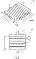
- Fig. 1 is a schematic diagram showing a single fuel cell unit suitable for use in the planar solid oxide fuel cell stack of this invention.
- Fuel cell unit 10 as shown, is an integral component comprising a relatively thick porous anode 16, a somewhat thicker porous cathode 15 (but much thinner than the anode), and a thin dense electrolyte 17 sandwiched therebetween.
- the fuel cell unit in accordance with this invention is quite rigid.
- the porous cathode 15 forms a plurality of substantially parallel oxidant gas flow channels 12 on a face of porous cathode 15 facing away from electrolyte 17 and porous anode 16 forms a plurality of fuel gas channels 18 on a face of porous anode 16 facing away from electrolyte 17.
- oxidant gas channels 12 extend from one side or edge of porous cathode 15 to an opposite edge and fuel gas channels 18, perpendicularly disposed with respect to oxidant gas channels 12, extend from one side or edge of porous anode 16 to an opposite edge. Because the oxidant gas channels 12 and fuel gas channels 18 are incorporated into the integral component fuel cell unit, the interconnect for electrically connecting one integral component fuel cell unit 10 to an adjacent integral component fuel cell unit in a fuel cell stack need not be bulky.
- FIG. 2 is a schematic diagram showing a five fuel cell unit solid oxide fuel cell stack in accordance with one embodiment of this invention.
- Fuel cell stack 20 comprises a plurality of integral component fuel cell units 10 with a thin, flexible metal foil interconnect 13 disposed between adjacent fuel cell units 10.
- gas manifolds 14 are in communication with fuel gas channels 18 and oxidant gas channels 12 to provide the requisite fuel gas to the porous anode 16 and oxidant gas to the porous cathode 15 of each integral component fuel cell unit 10 of solid oxide fuel cell stack 20.
- a flexible metal foil as interconnect 13 in accordance with the solid oxide fuel cell stack of this invention provides many advantages over traditional interconnects.
- the use of a flexible metal foil facilitates sealing between interconnect 13 and each integral component fuel cell unit 10 under a slight compressive stress without the necessity of a glass seal.
- the foil interconnect is metallic and thin, some amount of plastic deformation readily occurs under compression, thereby allowing for good sealing.
- a flexible foil insures a good electrical contact between the integral component fuel units 10 and the interconnects 13.
- the flexible metallic foil interconnect has a thickness in the range of about 1 mil to about 10 mils (25 microns - 250 microns). In accordance with a particularly preferred embodiment of this invention, the metallic foil interconnect has a thickness of about 5 mils.
- the entire fuel cell stack of this invention is not a rigid mass, unlike a glass-sealed stack.
- the solid oxide fuel cell stack of this invention can be subjected to rapid variations in temperature without the fear of cracking due to thermal stresses.
- the individual fuel cell units are quite sturdy and are thermally shock resistant due to the presence of a large amount of nickel in the anode, the thickest part of the integral component fuel cell unit.
- the interconnect is a flexible metallic foil which readily deforms, thermal expansion matching is not a requirement, in contrast to known designs which typically use either a ceramic interconnect or a thick metallic interconnect.
- thin metallic foils suitable for use in the solid oxide fuel cell stacks of this invention are made from commercially available alloys. These alloys are usually off-the-shelf items and are relatively inexpensive.
- the metallic foil interconnects of this invention are constructed of a superalloy.
- a superalloy is a metal alloy resistant to high temperature and typically comprises nickel, iron, chromium, and manganese.
- Examples of superalloys suitable for use as interconnects in the solid oxide fuel cell stack of this invention include, but are not limited to, austenetic stainless steel, Inconel, Haynes alloys, and Hastealloys.
- the solid oxide fuel cell stack comprises end plates 11 which function as current collectors.
- NiO and 8 mol. % yttria-stabilized zirconia (YSZ) powders were mixed and ball-milled in ethanol for 24 hours. After the well-mixed slurry was dried under vacuum, the powder was die-pressed using steel dies to create channels for a cross-flow arrangement. The amount of powder per plate was approximately 45 grams and the dimensions of the as-pressed cells were approximately 7 centimeters by 7 centimeters in lateral directions and 4 mm in thickness (after uniaxial pressing). The plates were bisqued in air at 1000°C for one hour. A slurry of YSZ in ethylene glycol was made containing 2 grams of YSZ per 10 ml of ethylene glycol. One side of each NiO+YSZ plate with cross-flow channels was subsequently painted with the YSZ paste. The plates were then sintered in air at 1400°C for two hours.
- YSZ yttria-stabilized zirconia
- LSM (La 0.8 Sr 0.2 MnO (3-x) ) powder using a mixture of MnO 2 , SrCO 3 and La 2 O 3 , was prepared by calcining in air at 1000°C for eight hours.
- YSZ powder was also calcined in air at 1200°C for one hour to coarsen the particle size.
- the calcined LSM and YSZ powders were mixed in equal amounts by weight to which ethanol was added. The slurry was subsequently ball-milled. After the powder mixture was dried, the powder was mixed in ethylene glycol in a ratio of 5 grams of LSM + YSZ to 5 ml of ethylene glycol to make a thick paste.
- the paste was applied on the YSZ-coated side of the sintered plates and they were heated at 400°C. This procedure was repeated until a LSM+YSZ cathode of the desired thickness, about 40-60 microns, was formed.
- Powder of LSM, without YSZ, in ethanol was ball-milled for 24 hours. After the powder mixture was dried, the LSM powder was mixed in ethylene glycol, 5 grams LSM to 5 ml ethylene glycol, to prepare a thick paste.
- the paste was applied on the LSM+YSZ painted plates and heated to about 160°C. The procedure was repeated until the desired thickness, about 150-200 microns, of LSM was obtained. Achieving a high enough thickness is important for minimizing the sheet resistance.
- the painted plates were heated in air to 1210°C for one hour. The maximum thickness of the cells, thickness varying due to the presence of grooves or channels, was about 3 mm.
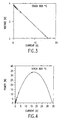
- a stack was assembled using four integral component fuel cell units and metallic (superalloy) interconnect foils. End plates, which served as current collectors, were also made of a superalloy. The diameter of the current collector rods (See Fig. 2) was 1.27 centimeters. Three voltage probes were introduced, one each attached to an interconnect. The stack was secured inside a metallic manifold with mica gaskets as edge seals. In order to improve the sealing, the stack was spring-loaded wherein the springs were outside the hot zone of the furnace. The stack was tested at 800°C with humidified hydrogen as the fuel and air as the oxidant. Reduction of NiO to Ni was achieved in-situ. The active area of the cell was estimated to be between 75 and 80 cm 2 . Fig.
- FIG. 3 shows voltage versus current for the stack and Fig. 4 shows a plot of the total power versus current.
- the maximum power measured was approximately 33 watts.
- the area specific resistance of the two inner repeat units (cell-interconnect) was about 0.5 cm 2 .
- the end repeat units had somewhat higher area specific resistances due to a poor contact between the current collectors and the end cells.
Landscapes
- Life Sciences & Earth Sciences (AREA)
- Engineering & Computer Science (AREA)
- Manufacturing & Machinery (AREA)
- Sustainable Development (AREA)
- Sustainable Energy (AREA)
- Chemical & Material Sciences (AREA)
- Chemical Kinetics & Catalysis (AREA)
- Electrochemistry (AREA)
- General Chemical & Material Sciences (AREA)
- Fuel Cell (AREA)
Claims (7)
- Empilement de piles à combustible en oxyde solide comprenant :une pluralité d'unités de piles à combustible planes à composant solidaire (10), chaque dite unité de piles à combustible planes à composant solidaire (10) comprenant une couche d'anode poreuse (16), une couche de cathode poreuse (15), et une couche d'électrolyte dense (17) disposée entre ladite couche d'anode poreuse (16) et ladite couche de cathode poreuse (15) ;ladite couche d'anode poreuse (16) formant une pluralité de canaux sensiblement parallèles pour combustible gazeux (18) sur une surface de l'anode dirigée à l'opposé de ladite couche d'électrolyte dense (17) et s'étendant d'un premier côté de l'anode vers un côté opposé de l'anode ;ladite couche de cathode poreuse (15) formant une pluralité de canaux sensiblement parallèles pour oxydant gazeux (18) sur une surface de la cathode dirigée à l'opposé de ladite couche d'électrolyte dense (17) et s'étendant d'un premier côté de la cathode vers un côté opposé de la cathode ; etune interconnexion en feuille métallique flexible sensiblement plate (13) disposée entre ladite couche d'anode poreuse (16) et ladite couche de cathode poreuse (15) desdites unités de piles à combustible à composant solidaire adjacentes.
- Empilement de piles à combustible en oxyde solide selon la revendication 1, dans lequel ladite interconnexion en feuille métallique flexible (13) a une épaisseur dans une gamme d'environ 1 mil (25 microns) à environ 10 mils (250 microns).
- Empilement de piles à combustible en oxyde solide selon la revendication 1 ou 2, dans lequel ladite interconnexion en feuille métallique flexible (13) comprend un superalliage.
- Empilement de piles à combustible en oxyde solide selon la revendication 3, dans lequel ledit superalliage est un alliage métallique constitué de nickel, de fer, de chrome et de manganèse.
- Empilement de piles à combustible en oxyde solide selon l'une quelconque des revendications précédentes, comprenant en outre une plaque d'extrémité disposée à chaque extrémité dudit empilement, chaque dite plaque d'extrémité servant de collecteur de courant.
- Empilement de piles à combustible en oxyde solide selon l'une quelconque des revendications précédentes, dans lequel ladite couche d'anode poreuse (16) a une épaisseur plus grande que ladite couche de cathode poreuse (15).
- Empilement de piles à combustible en oxyde solide selon l'une quelconque des revendications précédentes, dans lequel lesdits canaux sensiblement parallèles pour combustibles gazeux (18) sont sensiblement perpendiculaires auxdits canaux sensiblement parallèles pour oxydant gazeux (12).
Applications Claiming Priority (3)
| Application Number | Priority Date | Filing Date | Title |
|---|---|---|---|
| US09/332,237 US6106967A (en) | 1999-06-14 | 1999-06-14 | Planar solid oxide fuel cell stack with metallic foil interconnect |
| US332237 | 1999-06-14 | ||
| PCT/US2000/016387 WO2000077872A1 (fr) | 1999-06-14 | 2000-06-14 | Empilement plan de piles a combustible a oxyde solide a feuille d'interconnexion metallique |
Publications (2)
| Publication Number | Publication Date |
|---|---|
| EP1105929A1 EP1105929A1 (fr) | 2001-06-13 |
| EP1105929B1 true EP1105929B1 (fr) | 2005-04-06 |
Family
ID=23297343
Family Applications (1)
| Application Number | Title | Priority Date | Filing Date |
|---|---|---|---|
| EP00942816A Expired - Lifetime EP1105929B1 (fr) | 1999-06-14 | 2000-06-14 | Empilement plan de piles a combustible a oxyde solide a feuille d'interconnexion metallique |
Country Status (7)
| Country | Link |
|---|---|
| US (1) | US6106967A (fr) |
| EP (1) | EP1105929B1 (fr) |
| AT (1) | ATE292846T1 (fr) |
| AU (1) | AU5738600A (fr) |
| CA (1) | CA2391487C (fr) |
| DE (1) | DE60019238T2 (fr) |
| WO (1) | WO2000077872A1 (fr) |
Families Citing this family (66)
| Publication number | Priority date | Publication date | Assignee | Title |
|---|---|---|---|---|
| US6567011B1 (en) * | 1999-10-14 | 2003-05-20 | Universal Electronics Inc. | Media system and remote control for same |
| US6479178B2 (en) * | 1999-11-16 | 2002-11-12 | Northwestern University | Direct hydrocarbon fuel cells |
| US7482077B2 (en) * | 1999-11-16 | 2009-01-27 | Northwestern University | Direct hydrocarbon fuel cells |
| CA2406312A1 (fr) | 2000-04-18 | 2001-10-25 | Celltech Power, Inc. | Dispositif electrochimique et procedes de conversion d'energie |
| DE10044703B4 (de) * | 2000-09-09 | 2013-10-17 | Elringklinger Ag | Brennstoffzelleneinheit, Brennstoffzellenblockverbund und Verfahren zum Herstellen eines Brennstoffzellenblockverbunds |
| GB0024106D0 (en) | 2000-10-03 | 2000-11-15 | Rolls Royce Plc | A solid oxide fuel cell stack and a method of manufacturing a solid oxide fuel cell stack |
| US6770395B2 (en) * | 2000-10-23 | 2004-08-03 | Materials And Systems Research, Inc. | Internally manifolded, planar solid oxide fuel cell (SOFC) stack with an inexpensive interconnect |
| US6613468B2 (en) | 2000-12-22 | 2003-09-02 | Delphi Technologies, Inc. | Gas diffusion mat for fuel cells |
| US7709124B2 (en) * | 2001-04-10 | 2010-05-04 | Northwestern University | Direct hydrocarbon fuel cells |
| US20040219423A1 (en) * | 2001-04-27 | 2004-11-04 | Tunney Cathal Joseph | Metal-supported solid electrolyte electrochemical cell and multi cell reactors incorporating same |
| US6772501B2 (en) * | 2001-07-23 | 2004-08-10 | Itn Energy Systems, Inc. | Apparatus and method for the design and manufacture of thin-film electrochemical devices |
| US7008716B2 (en) * | 2001-10-01 | 2006-03-07 | Delphi Technologies, Inc. | Gasket material for a fuel cell |
| US6821667B2 (en) * | 2001-10-01 | 2004-11-23 | Delphi Technologies, Inc. | Fuel cell stack having foil interconnects and laminated spacers |
| US6495279B1 (en) * | 2001-10-02 | 2002-12-17 | Ford Global Technologies, Inc. | Ultrahigh power density miniaturized solid-oxide fuel cell |
| WO2003041196A1 (fr) * | 2001-11-07 | 2003-05-15 | Northwestern University | Anodes adaptees a divers combustibles destines a des piles a combustible a oxyde solide |
| EP1328035A1 (fr) | 2002-01-09 | 2003-07-16 | HTceramix S.A. - High Technology Electroceramics | PEN de pile à combustible à oxydes solide |
| US7222406B2 (en) * | 2002-04-26 | 2007-05-29 | Battelle Memorial Institute | Methods for making a multi-layer seal for electrochemical devices |
| US20030215689A1 (en) * | 2002-05-16 | 2003-11-20 | Keegan Kevin R. | Solid oxide fuel cell with a metal foam seal |
| US7842434B2 (en) * | 2005-06-15 | 2010-11-30 | Ati Properties, Inc. | Interconnects for solid oxide fuel cells and ferritic stainless steels adapted for use with solid oxide fuel cells |
| US8158057B2 (en) | 2005-06-15 | 2012-04-17 | Ati Properties, Inc. | Interconnects for solid oxide fuel cells and ferritic stainless steels adapted for use with solid oxide fuel cells |
| US7981561B2 (en) | 2005-06-15 | 2011-07-19 | Ati Properties, Inc. | Interconnects for solid oxide fuel cells and ferritic stainless steels adapted for use with solid oxide fuel cells |
| US7153601B2 (en) * | 2002-10-29 | 2006-12-26 | Hewlett-Packard Development Company, L.P. | Fuel cell with embedded current collector |
| AU2003295497A1 (en) * | 2002-11-16 | 2004-06-15 | George Bevan Kirby Meacham | Diffusion stabilized gas barriers |
| MXPA05006424A (es) * | 2002-12-16 | 2005-09-08 | Univ Pennsylvania | Anodos de ceramica de alto desempeno y metodo para producirlos. |
| US6958196B2 (en) * | 2003-02-21 | 2005-10-25 | Trustees Of The University Of Pennsylvania | Porous electrode, solid oxide fuel cell, and method of producing the same |
| US7943270B2 (en) | 2003-06-10 | 2011-05-17 | Celltech Power Llc | Electrochemical device configurations |
| WO2004112175A2 (fr) | 2003-06-10 | 2004-12-23 | Celltech Power, Inc. | Facilitateur d'oxydation |
| US20050053819A1 (en) * | 2003-07-18 | 2005-03-10 | Paz Eduardo E. | Solid oxide fuel cell interconnect with catalyst coating |
| US20050092175A1 (en) * | 2003-10-29 | 2005-05-05 | Meacham G.B. K. | Noble metal gas barriers |
| US7074255B2 (en) * | 2003-10-29 | 2006-07-11 | Meacham G B Kirby | Noble metal gas barriers |
| US7226687B2 (en) * | 2004-05-08 | 2007-06-05 | Meacham G B Kirby | Fuel cell assemblies using metallic bipolar separators |
| US20060040168A1 (en) * | 2004-08-20 | 2006-02-23 | Ion America Corporation | Nanostructured fuel cell electrode |
| KR100637490B1 (ko) * | 2004-09-17 | 2006-10-20 | 삼성에스디아이 주식회사 | 연료 전지용 스택과 이를 갖는 연료 전지 시스템 |
| DE102004056422A1 (de) | 2004-11-23 | 2006-05-24 | Forschungszentrum Jülich GmbH | Gasverteilerplatte für eine Hochtemperatur-Brennstoffzelle |
| US7513968B1 (en) | 2005-07-11 | 2009-04-07 | The United States Of America As Represented By The Secretary Of The Navy | Fabrication of magnesium-titanium template for a magnesium hydrogen peroxide fuel cell |
| WO2007087305A2 (fr) * | 2006-01-23 | 2007-08-02 | Bloom Energy Corporation | Pile à combustible à oxyde solide intégrée et convertisseur de combustible |
| US7659022B2 (en) | 2006-08-14 | 2010-02-09 | Modine Manufacturing Company | Integrated solid oxide fuel cell and fuel processor |
| US9190693B2 (en) | 2006-01-23 | 2015-11-17 | Bloom Energy Corporation | Modular fuel cell system |
| US8241801B2 (en) | 2006-08-14 | 2012-08-14 | Modine Manufacturing Company | Integrated solid oxide fuel cell and fuel processor |
| US20080118802A1 (en) * | 2006-11-16 | 2008-05-22 | Peter Szrama | Fully Catalyzed Membrane Assembly With Attached Border |
| WO2008085488A1 (fr) * | 2006-12-28 | 2008-07-17 | Saint-Gobain Ceramics & Plastics, Inc. | Interconnexions en titanate et en métal pour piles à combustible à oxyde solide |
| US20090186250A1 (en) * | 2006-12-28 | 2009-07-23 | Saint-Gobain Ceramics & Plastics, Inc. | Bilayer interconnects for solid oxide fuel cells |
| US8920997B2 (en) | 2007-07-26 | 2014-12-30 | Bloom Energy Corporation | Hybrid fuel heat exchanger—pre-reformer in SOFC systems |
| US8852820B2 (en) | 2007-08-15 | 2014-10-07 | Bloom Energy Corporation | Fuel cell stack module shell with integrated heat exchanger |
| WO2009105191A2 (fr) | 2008-02-19 | 2009-08-27 | Bloom Energy Corporation | Système de piles à combustible contenant un dispositif d'oxydation de gaz résiduaire d'anode et un échangeur de chaleur/reformeur hybride |
| US8968958B2 (en) | 2008-07-08 | 2015-03-03 | Bloom Energy Corporation | Voltage lead jumper connected fuel cell columns |
| US8883368B2 (en) * | 2008-11-21 | 2014-11-11 | Ballard Power Systems Inc. | Solid oxide fuel cell having rigidized support including nickel-based alloy |
| US20110212379A1 (en) * | 2008-11-21 | 2011-09-01 | Jean Yamanis | Method of forming a fuel cell sheet |
| EP2377189B1 (fr) | 2008-12-18 | 2018-05-02 | Saint-Gobain Ceramics & Plastics Inc. | Interconnexion en titanate de lanthane et de strontium hautement frittable par dopage |
| US20110177423A1 (en) * | 2010-01-21 | 2011-07-21 | Anton Nachtmann | Five-Layer Membrane Electrode Assembly with Attached Border and Method of Making Same |
| WO2012040253A1 (fr) * | 2010-09-20 | 2012-03-29 | Nextech Materials, Ltd. | Unité de répétition de pile à combustible et empilement de piles à combustible |
| US8440362B2 (en) | 2010-09-24 | 2013-05-14 | Bloom Energy Corporation | Fuel cell mechanical components |
| EP2661782B1 (fr) | 2011-01-06 | 2018-10-03 | Bloom Energy Corporation | Composants d'enceinte thermique (hot box) pour pile à combustible à oxyde solide |
| WO2013096756A1 (fr) | 2011-12-22 | 2013-06-27 | Saint-Gobain Ceramics & Plastics, Inc. | Interconnexions de pile à combustible à oxyde solide comprenant un matériau d'interconnexion céramique et du zircone partiellement stabilisé |
| EP2819227A4 (fr) * | 2012-02-23 | 2015-11-25 | Toppan Printing Co Ltd | Jonction film-électrode destinée à une pile à combustible à polymère à l'état solide et son procédé de fabrication et pile à combustible à polymère à l'état solide |
| FR2996065B1 (fr) | 2012-09-26 | 2017-02-24 | Commissariat Energie Atomique | Composant constituant un interconnecteur d'electrolyseur eht ou de pile a combustible sofc et procedes de realisation associes |
| US9755263B2 (en) | 2013-03-15 | 2017-09-05 | Bloom Energy Corporation | Fuel cell mechanical components |
| TWI638483B (zh) | 2013-10-23 | 2018-10-11 | 美商博隆能源股份有限公司 | 用於燃料電池系統之陽極復熱器及其操作方法 |
| CN103545542B (zh) * | 2013-11-14 | 2015-11-25 | 中国科学院宁波材料技术与工程研究所 | 平板式固体氧化物燃料电池系统 |
| TWI663771B (zh) | 2014-02-12 | 2019-06-21 | 美商博隆能源股份有限公司 | 多個燃料電池和電力電子供給負載並聯以允許整合電化學阻抗頻譜(eis)之燃料電池系統之結構及方法 |
| FR3024985B1 (fr) * | 2014-08-22 | 2020-01-17 | Commissariat A L'energie Atomique Et Aux Energies Alternatives | Procede d'electrolyse ou de co-electrolyse a haute temperature, procede de production d'electricite par pile a combustible sofc, interconnecteurs, reacteurs et procedes de fonctionnement associes. |
| US10651496B2 (en) | 2015-03-06 | 2020-05-12 | Bloom Energy Corporation | Modular pad for a fuel cell system |
| US11398634B2 (en) | 2018-03-27 | 2022-07-26 | Bloom Energy Corporation | Solid oxide fuel cell system and method of operating the same using peak shaving gas |
| JP7333795B2 (ja) * | 2018-05-31 | 2023-08-25 | ブルーム エネルギー コーポレイション | クロスフロー型のインターコネクト及び同インターコネクトを含む燃料電池システム |
| CN112310454B (zh) * | 2019-07-31 | 2022-09-20 | 中国科学院宁波材料技术与工程研究所 | 一种基于对称双阴极结构固体氧化物燃料电池电堆的集成方法 |
| KR20230000972A (ko) | 2021-06-25 | 2023-01-03 | 블룸 에너지 코퍼레이션 | 연료 전지 시스템의 건전성 및 성능을 최대화하기 위한 가변적이고 예측할 수 없는 가스 조성 변화의 처리 |
Family Cites Families (17)
| Publication number | Priority date | Publication date | Assignee | Title |
|---|---|---|---|---|
| US34213A (en) * | 1862-01-21 | Improvement in track-clearers in mowing-machines | ||
| FR1367534A (fr) * | 1963-05-17 | 1964-07-24 | Comp Generale Electricite | Pile électrique à combustibles |
| US3785867A (en) * | 1972-01-31 | 1974-01-15 | Int Nickel Co | Battery plates comprising a multiplicity of perforated metallic foil elements and a battery utilizing same |
| US4588661A (en) * | 1984-08-27 | 1986-05-13 | Engelhard Corporation | Fabrication of gas impervious edge seal for a bipolar gas distribution assembly for use in a fuel cell |
| US4629537A (en) | 1985-05-17 | 1986-12-16 | Hsu Michael S | Compact, light-weight, solid-oxide electrochemical converter |
| US4761349A (en) * | 1987-03-19 | 1988-08-02 | University Of Chicago | Solid oxide fuel cell with monolithic core |
| DK166747B1 (da) * | 1989-12-05 | 1993-07-05 | Topsoe Haldor As | Braendselscelle og braendselscellestabel |
| EP0530451B1 (fr) * | 1991-09-03 | 1998-01-21 | Sanyo Electric Co., Ltd. | Système de piles à combustible à oxydes solides |
| US5258240A (en) * | 1991-10-11 | 1993-11-02 | Westinghouse Electric Corp. | Solid oxide fuel cell generator |
| US5750279A (en) * | 1992-02-28 | 1998-05-12 | Air Products And Chemicals, Inc. | Series planar design for solid electrolyte oxygen pump |
| US5292600A (en) * | 1992-08-13 | 1994-03-08 | H-Power Corp. | Hydrogen power cell |
| US5298342A (en) * | 1992-10-20 | 1994-03-29 | M-C Power Corporation | Fuel cell crossover arrestor and pressure seal |
| US5496655A (en) * | 1994-10-12 | 1996-03-05 | Lockheed Idaho Technologies Company | Catalytic bipolar interconnection plate for use in a fuel cell |
| US5993986A (en) * | 1995-11-16 | 1999-11-30 | The Dow Chemical Company | Solide oxide fuel cell stack with composite electrodes and method for making |
| AUPN876896A0 (en) * | 1996-03-18 | 1996-04-18 | Ceramic Fuel Cells Limited | An electrical interconnect for a planar fuel cell |
| US5935727A (en) * | 1997-04-10 | 1999-08-10 | The Dow Chemical Company | Solid oxide fuel cells |
| AUPO724997A0 (en) * | 1997-06-10 | 1997-07-03 | Ceramic Fuel Cells Limited | A fuel cell assembly |
-
1999
- 1999-06-14 US US09/332,237 patent/US6106967A/en not_active Expired - Lifetime
-
2000
- 2000-06-14 AT AT00942816T patent/ATE292846T1/de not_active IP Right Cessation
- 2000-06-14 EP EP00942816A patent/EP1105929B1/fr not_active Expired - Lifetime
- 2000-06-14 AU AU57386/00A patent/AU5738600A/en not_active Abandoned
- 2000-06-14 WO PCT/US2000/016387 patent/WO2000077872A1/fr not_active Ceased
- 2000-06-14 CA CA002391487A patent/CA2391487C/fr not_active Expired - Fee Related
- 2000-06-14 DE DE60019238T patent/DE60019238T2/de not_active Expired - Lifetime
Also Published As
| Publication number | Publication date |
|---|---|
| CA2391487A1 (fr) | 2000-12-21 |
| ATE292846T1 (de) | 2005-04-15 |
| US6106967A (en) | 2000-08-22 |
| CA2391487C (fr) | 2009-09-29 |
| DE60019238D1 (de) | 2005-05-12 |
| WO2000077872A1 (fr) | 2000-12-21 |
| DE60019238T2 (de) | 2005-09-01 |
| AU5738600A (en) | 2001-01-02 |
| EP1105929A1 (fr) | 2001-06-13 |
Similar Documents
| Publication | Publication Date | Title |
|---|---|---|
| EP1105929B1 (fr) | Empilement plan de piles a combustible a oxyde solide a feuille d'interconnexion metallique | |
| JP4960593B2 (ja) | 電気化学的電池スタック組立体 | |
| US9123936B2 (en) | Solid oxide fuel cell apparatus | |
| US7816055B2 (en) | Compact fuel cell | |
| WO2001089017A1 (fr) | Piles a combustible a electrolyte solide haute performance | |
| EP1369949B1 (fr) | Pile à combustible à électrolyte solide et son procédé de fabrication | |
| EP0551380B1 (fr) | Electrode creuse de pile electrochimique pourvue d'au moins une entree et d'une sortie de gaz et pile electrochimique contenant cette electrode | |
| JPH10189017A (ja) | ハニカム構造固体電解質型燃料電池のガスシール構造 | |
| JP2009520315A (ja) | 電気化学電池のホルダ及びスタック | |
| US11394036B2 (en) | Fuel cell power generation unit and fuel cell stack | |
| JPH09129252A (ja) | 高耐久性固体電解質燃料電池およびその製造方法 | |
| JP6748518B2 (ja) | 電気化学反応セルの製造方法 | |
| JPH06325787A (ja) | 固体電解質型燃料電池 | |
| JP3244310B2 (ja) | 固体電解質型燃料電池 | |
| JP2774227B2 (ja) | 固体電解質型燃料電池スタックの接合方法 | |
| JPH1186886A (ja) | 固体電解質型燃料電池 | |
| JP2012142241A (ja) | 固体酸化物形燃料電池用単セルの製造方法 | |
| KR102198390B1 (ko) | 급속 구동 조건에서 안정한 직접 연소형 고체산화물 연료전지 | |
| JP2980921B2 (ja) | 平板型固体電解質燃料電池 | |
| JPH0722058A (ja) | 平板状固体電解質燃料電池 | |
| JPH05151982A (ja) | 固体電解質型燃料電池 | |
| JP5727567B2 (ja) | 固体酸化物形燃料電池、固体酸化物形燃料電池スタックおよびスペーサ | |
| JPH09147884A (ja) | 平板型固体電解質燃料電池 | |
| JP3301558B2 (ja) | 平板状固体電解質燃料電池 | |
| JPH0562694A (ja) | 固体電解質型燃料電池 |
Legal Events
| Date | Code | Title | Description |
|---|---|---|---|
| PUAI | Public reference made under article 153(3) epc to a published international application that has entered the european phase |
Free format text: ORIGINAL CODE: 0009012 |
|
| AK | Designated contracting states |
Kind code of ref document: A1 Designated state(s): AT BE CH CY DE DK ES FI FR GB GR IE IT LI LU MC NL PT SE |
|
| AX | Request for extension of the european patent |
Free format text: AL;LT;LV;MK;RO;SI |
|
| 17P | Request for examination filed |
Effective date: 20010621 |
|
| 17Q | First examination report despatched |
Effective date: 20040408 |
|
| GRAP | Despatch of communication of intention to grant a patent |
Free format text: ORIGINAL CODE: EPIDOSNIGR1 |
|
| GRAS | Grant fee paid |
Free format text: ORIGINAL CODE: EPIDOSNIGR3 |
|
| GRAA | (expected) grant |
Free format text: ORIGINAL CODE: 0009210 |
|
| AK | Designated contracting states |
Kind code of ref document: B1 Designated state(s): AT BE CH CY DE DK ES FI FR GB GR IE IT LI LU MC NL PT SE |
|
| PG25 | Lapsed in a contracting state [announced via postgrant information from national office to epo] |
Ref country code: AT Free format text: LAPSE BECAUSE OF FAILURE TO SUBMIT A TRANSLATION OF THE DESCRIPTION OR TO PAY THE FEE WITHIN THE PRESCRIBED TIME-LIMIT Effective date: 20050406 Ref country code: LI Free format text: LAPSE BECAUSE OF FAILURE TO SUBMIT A TRANSLATION OF THE DESCRIPTION OR TO PAY THE FEE WITHIN THE PRESCRIBED TIME-LIMIT Effective date: 20050406 Ref country code: FI Free format text: LAPSE BECAUSE OF FAILURE TO SUBMIT A TRANSLATION OF THE DESCRIPTION OR TO PAY THE FEE WITHIN THE PRESCRIBED TIME-LIMIT Effective date: 20050406 Ref country code: CH Free format text: LAPSE BECAUSE OF FAILURE TO SUBMIT A TRANSLATION OF THE DESCRIPTION OR TO PAY THE FEE WITHIN THE PRESCRIBED TIME-LIMIT Effective date: 20050406 Ref country code: BE Free format text: LAPSE BECAUSE OF FAILURE TO SUBMIT A TRANSLATION OF THE DESCRIPTION OR TO PAY THE FEE WITHIN THE PRESCRIBED TIME-LIMIT Effective date: 20050406 Ref country code: NL Free format text: LAPSE BECAUSE OF FAILURE TO SUBMIT A TRANSLATION OF THE DESCRIPTION OR TO PAY THE FEE WITHIN THE PRESCRIBED TIME-LIMIT Effective date: 20050406 |
|
| REG | Reference to a national code |
Ref country code: GB Ref legal event code: FG4D |
|
| REG | Reference to a national code |
Ref country code: CH Ref legal event code: EP |
|
| REG | Reference to a national code |
Ref country code: IE Ref legal event code: FG4D |
|
| REF | Corresponds to: |
Ref document number: 60019238 Country of ref document: DE Date of ref document: 20050512 Kind code of ref document: P |
|
| PG25 | Lapsed in a contracting state [announced via postgrant information from national office to epo] |
Ref country code: CY Free format text: LAPSE BECAUSE OF FAILURE TO SUBMIT A TRANSLATION OF THE DESCRIPTION OR TO PAY THE FEE WITHIN THE PRESCRIBED TIME-LIMIT Effective date: 20050614 Ref country code: LU Free format text: LAPSE BECAUSE OF NON-PAYMENT OF DUE FEES Effective date: 20050614 Ref country code: IE Free format text: LAPSE BECAUSE OF NON-PAYMENT OF DUE FEES Effective date: 20050614 |
|
| PG25 | Lapsed in a contracting state [announced via postgrant information from national office to epo] |
Ref country code: MC Free format text: LAPSE BECAUSE OF NON-PAYMENT OF DUE FEES Effective date: 20050630 |
|
| PG25 | Lapsed in a contracting state [announced via postgrant information from national office to epo] |
Ref country code: SE Free format text: LAPSE BECAUSE OF FAILURE TO SUBMIT A TRANSLATION OF THE DESCRIPTION OR TO PAY THE FEE WITHIN THE PRESCRIBED TIME-LIMIT Effective date: 20050706 Ref country code: DK Free format text: LAPSE BECAUSE OF FAILURE TO SUBMIT A TRANSLATION OF THE DESCRIPTION OR TO PAY THE FEE WITHIN THE PRESCRIBED TIME-LIMIT Effective date: 20050706 Ref country code: GR Free format text: LAPSE BECAUSE OF FAILURE TO SUBMIT A TRANSLATION OF THE DESCRIPTION OR TO PAY THE FEE WITHIN THE PRESCRIBED TIME-LIMIT Effective date: 20050706 |
|
| PG25 | Lapsed in a contracting state [announced via postgrant information from national office to epo] |
Ref country code: ES Free format text: LAPSE BECAUSE OF FAILURE TO SUBMIT A TRANSLATION OF THE DESCRIPTION OR TO PAY THE FEE WITHIN THE PRESCRIBED TIME-LIMIT Effective date: 20050717 |
|
| PG25 | Lapsed in a contracting state [announced via postgrant information from national office to epo] |
Ref country code: PT Free format text: LAPSE BECAUSE OF FAILURE TO SUBMIT A TRANSLATION OF THE DESCRIPTION OR TO PAY THE FEE WITHIN THE PRESCRIBED TIME-LIMIT Effective date: 20050908 |
|
| NLV1 | Nl: lapsed or annulled due to failure to fulfill the requirements of art. 29p and 29m of the patents act | ||
| REG | Reference to a national code |
Ref country code: CH Ref legal event code: PL |
|
| PLBE | No opposition filed within time limit |
Free format text: ORIGINAL CODE: 0009261 |
|
| STAA | Information on the status of an ep patent application or granted ep patent |
Free format text: STATUS: NO OPPOSITION FILED WITHIN TIME LIMIT |
|
| ET | Fr: translation filed | ||
| REG | Reference to a national code |
Ref country code: IE Ref legal event code: MM4A |
|
| 26N | No opposition filed |
Effective date: 20060110 |
|
| REG | Reference to a national code |
Ref country code: GB Ref legal event code: 732E |
|
| REG | Reference to a national code |
Ref country code: FR Ref legal event code: RM Ref country code: FR Ref legal event code: TP |
|
| PGFP | Annual fee paid to national office [announced via postgrant information from national office to epo] |
Ref country code: FR Payment date: 20100630 Year of fee payment: 11 |
|
| PGFP | Annual fee paid to national office [announced via postgrant information from national office to epo] |
Ref country code: IT Payment date: 20100625 Year of fee payment: 11 |
|
| PGFP | Annual fee paid to national office [announced via postgrant information from national office to epo] |
Ref country code: DE Payment date: 20100629 Year of fee payment: 11 |
|
| PG25 | Lapsed in a contracting state [announced via postgrant information from national office to epo] |
Ref country code: IT Free format text: LAPSE BECAUSE OF NON-PAYMENT OF DUE FEES Effective date: 20110614 |
|
| REG | Reference to a national code |
Ref country code: FR Ref legal event code: ST Effective date: 20120229 |
|
| REG | Reference to a national code |
Ref country code: DE Ref legal event code: R119 Ref document number: 60019238 Country of ref document: DE Effective date: 20120103 |
|
| PG25 | Lapsed in a contracting state [announced via postgrant information from national office to epo] |
Ref country code: DE Free format text: LAPSE BECAUSE OF NON-PAYMENT OF DUE FEES Effective date: 20120103 Ref country code: FR Free format text: LAPSE BECAUSE OF NON-PAYMENT OF DUE FEES Effective date: 20110630 |
|
| PGFP | Annual fee paid to national office [announced via postgrant information from national office to epo] |
Ref country code: GB Payment date: 20161012 Year of fee payment: 17 |
|
| GBPC | Gb: european patent ceased through non-payment of renewal fee |
Effective date: 20170614 |
|
| PG25 | Lapsed in a contracting state [announced via postgrant information from national office to epo] |
Ref country code: GB Free format text: LAPSE BECAUSE OF NON-PAYMENT OF DUE FEES Effective date: 20170614 |