EP1106043B1 - Verfahren und system zur inspektion eines bauteils mit anschlüssen und zum erfassen der korrekten bestückungsposition - Google Patents
Verfahren und system zur inspektion eines bauteils mit anschlüssen und zum erfassen der korrekten bestückungsposition Download PDFInfo
- Publication number
- EP1106043B1 EP1106043B1 EP00936922A EP00936922A EP1106043B1 EP 1106043 B1 EP1106043 B1 EP 1106043B1 EP 00936922 A EP00936922 A EP 00936922A EP 00936922 A EP00936922 A EP 00936922A EP 1106043 B1 EP1106043 B1 EP 1106043B1
- Authority
- EP
- European Patent Office
- Prior art keywords
- component
- lead
- leads
- illuminating beam
- procedure
- Prior art date
- Legal status (The legal status is an assumption and is not a legal conclusion. Google has not performed a legal analysis and makes no representation as to the accuracy of the status listed.)
- Expired - Lifetime
Links
- 238000000034 method Methods 0.000 title claims abstract description 57
- 238000005259 measurement Methods 0.000 claims abstract description 8
- 230000000694 effects Effects 0.000 claims abstract description 7
- 238000007689 inspection Methods 0.000 claims description 29
- 238000003780 insertion Methods 0.000 claims description 5
- 230000037431 insertion Effects 0.000 claims description 5
- 238000010586 diagram Methods 0.000 description 7
- 230000006870 function Effects 0.000 description 4
- 238000004364 calculation method Methods 0.000 description 1
- 239000003086 colorant Substances 0.000 description 1
- 238000001514 detection method Methods 0.000 description 1
- 230000009977 dual effect Effects 0.000 description 1
- 238000005516 engineering process Methods 0.000 description 1
- 238000005286 illumination Methods 0.000 description 1
- WABPQHHGFIMREM-UHFFFAOYSA-N lead(0) Chemical compound [Pb] WABPQHHGFIMREM-UHFFFAOYSA-N 0.000 description 1
- 238000004519 manufacturing process Methods 0.000 description 1
- 230000000979 retarding effect Effects 0.000 description 1
- YLJREFDVOIBQDA-UHFFFAOYSA-N tacrine Chemical compound C1=CC=C2C(N)=C(CCCC3)C3=NC2=C1 YLJREFDVOIBQDA-UHFFFAOYSA-N 0.000 description 1
- 229960001685 tacrine Drugs 0.000 description 1
Images




Classifications
-
- H—ELECTRICITY
- H05—ELECTRIC TECHNIQUES NOT OTHERWISE PROVIDED FOR
- H05K—PRINTED CIRCUITS; CASINGS OR CONSTRUCTIONAL DETAILS OF ELECTRIC APPARATUS; MANUFACTURE OF ASSEMBLAGES OF ELECTRICAL COMPONENTS
- H05K13/00—Apparatus or processes specially adapted for manufacturing or adjusting assemblages of electric components
- H05K13/04—Mounting of components, e.g. of leadless components
- H05K13/0404—Pick-and-place heads or apparatus, e.g. with jaws
- H05K13/0413—Pick-and-place heads or apparatus, e.g. with jaws with orientation of the component while holding it; Drive mechanisms for gripping tools, e.g. lifting, lowering or turning of gripping tools
-
- G—PHYSICS
- G01—MEASURING; TESTING
- G01B—MEASURING LENGTH, THICKNESS OR SIMILAR LINEAR DIMENSIONS; MEASURING ANGLES; MEASURING AREAS; MEASURING IRREGULARITIES OF SURFACES OR CONTOURS
- G01B11/00—Measuring arrangements characterised by the use of optical techniques
- G01B11/24—Measuring arrangements characterised by the use of optical techniques for measuring contours or curvatures
- G01B11/2433—Measuring arrangements characterised by the use of optical techniques for measuring contours or curvatures for measuring outlines by shadow casting
-
- H—ELECTRICITY
- H05—ELECTRIC TECHNIQUES NOT OTHERWISE PROVIDED FOR
- H05K—PRINTED CIRCUITS; CASINGS OR CONSTRUCTIONAL DETAILS OF ELECTRIC APPARATUS; MANUFACTURE OF ASSEMBLAGES OF ELECTRICAL COMPONENTS
- H05K13/00—Apparatus or processes specially adapted for manufacturing or adjusting assemblages of electric components
- H05K13/08—Monitoring manufacture of assemblages
- H05K13/081—Integration of optical monitoring devices in assembly lines; Processes using optical monitoring devices specially adapted for controlling devices or machines in assembly lines
- H05K13/0813—Controlling of single components prior to mounting, e.g. orientation, component geometry
Definitions
- the present invention relates to a procedure and system for inspecting a component with leads to determine its fitness for assembly in conjunction with automatic circuit board assembly performed using an assembly robot before the component is placed on a circuit board, said component having a row of at least two leads to be inserted into corresponding holes in the circuit board, said robot being equipped with a gripper for taking hold of the component.
- an assembly robot For automatic placement of components on a circuit board, usually an assembly robot is used in a computer-controlled assembly robot cell provided with a circuit board conveyor, which brings the circuit board to an assembly station located within the working area of the robot.
- the assembly robot is preferably a xyzw-robot (also called as a xyzrz-robot) which refers to a robot having four degrees of freedom (x, y, z, w).
- the robot is provided with grippers for taking hold of a component.
- the robot is capable of three-dimensional motion in x, y and z directions which form the three degrees of freedom and the rotation of the grippers about z-axis forms the fourth degree of freedom (w).
- the robot is e.g.
- a portal robot working in the space above the circuit board conveyor. It fetches one component at a time from a component feed device and places it in a specified location on the circuit board. Before being placed on the circuit board, the component must be inspected to determine whether it is fit for assembly. The leads of the component must be aligned in a sufficiently straight line and they must not have too much sideways bends because in that case they would not go through the holes in the circuit board. It is also important to check the position of the leads of the component in relation to the gripper.
- a prior-art system comprises an upward directed camera disposed at a fixed location beside a circuit board conveyor.
- a robot first takes each component, with the leads pointing downward, onto the optics of the camera, which takes a picture of the tips of the leads from below, whereupon a vision program comprised in the system computes the positions of the leads on the basis of the image and compares them with approved reference values. If the vision software finds that the detected lead positions are not within acceptable tolerances, i.e. one or more leads have been bent, then the software instructs the robot to reject the component and get a new one for inspection and assembly.
- a problem with this prior-art procedure and system is that it is very expensive as it incorporates many components: a camera, lighting, a machine vision processor with software to develop applications, a video monitor to display images, user interface etc.
- a further problem is that there are many factors impairing the reliability of machine vision.
- the image may be blurred due to reflections, and the contrast between the component body and the leads may be poor.
- the colour of the component body visible on the background of the leads may cause blurring of the image.
- the leads may not be distinct enough from the background. In order to be able to distinguish the leads from the background of the component bodies of different colours one would need to arrange different kind of illuminations specific for each colour.
- this problem could be solved in the machine vision system by taking two pictures of the component from its two sides from one end of the lead row instead of photographing it from below.
- Such a solution is applicable in the case of small components that fit completely in the image area of the camera.
- the problems associated with the machine vision system become more pronounced especially in the case of large components that do not fit in the image area of the camera.
- a further problem is that taking the component aside from the route between the component feed device and the circuit board in order to take a picture of it significantly retards the assembly process.
- US-A-5 309 223 describes a method and a system for inspecting the leads of a component, according the characterising portions of claim 1 and 18.
- the object of the present invention is to eliminate the drawbacks described above.
- a specific object of the present invention is to disclose a simple, cheap and reliable inspection procedure and system for inspecting a component to determine its fitness for assembly without substantially retarding the assembly process.
- a further object of the invention is to disclose a procedure and system that allow a component fitness inspection to be performed while the component is being transferred to an assembly station, without stopping the transferring motion.
- An additional object of the invention is to disclose a procedure and system by which it is possible to reliably inspect the leads of components and ascertain that the leads have not been bent, on all components regardless of the number of leads (e.g. 2 - 500) and the colour and lead profile of the component.
- a narrow illuminating beam is directed at a light-sensitive detector; the component and the illuminating beam are moved in relation to each other in the direction of the width and/or length of the row of leads so that the position as a function of time is known and so that the leads of the component pass through the illuminating beam, the illuminating beam thus reaching the light-sensitive detector when it falls between leads, whereas when it falls on leads, the leads cast a shadow, preventing the beam from reaching the light-sensitive detector; the pulse produced by the light-sensitive detector as a result of the illuminating beam being intercepted by the shadowing effect of the leads is registered; based on the pulse, the width of the lead row and/or the distance between adjacent leads rows are/is computed; the width of the lead row and/or the distance between adjacent leads rows are/is compared with a specified allowed respective limit value; and the component is placed on the circuit board if the width and/or the distance between adjacent lead rows computed on the basis of the measurement are/is
- Width of the lead row refers to the width perpendicular to the length of the row.
- the row width corresponds to the width of one lead, i.e. when the leads are in a straight line.
- a lateral divergence of a lead increases the width of the row.
- the row width can be assigned a limit value that it must not exceed. The invention is based on the insight that measuring the width of the lead row and/or the distance between two adjacent rows is a sufficient expedient for detecting bent leads.
- the invention has the advantage that it provides a fast and reliable procedure that does not retard the assembly process and is applicable for use with all components with leads regardless of the number of leads.
- the system is cheap, its production costs are about a tenth of the costs of a machine vision system and it is more reliable than the latter.
- the procedure and system allow a component to be inspected while it is being transferred to an assembly station, without stopping the transferring movement.
- a further advantage provided by the invention is that an inspection of leads can be performed on all components no matter how many leads (e.g. 2 - 500) the component has, regardless of component colour and lead profile.
- component is taken hold of and moved by means of a gripper of an xyzw-robot.
- the lead row of the component is inspected by moving the component in relation to a stationary illuminating beam.
- the component is passed cross the illuminating beam in the direction of the width and/or length of the row of the leads.
- the width of the lead row and/or the distance between adjacent lead rows is computed on the basis of the start and end instants of the pulse.
- the illuminating beam is directed at the light-sensitive detector in a horizontal plane in the x-direction.
- x-direction refers to a horizontal direction which is the same as the direction of motion of the circuit board conveyor.
- y-direction means a horizontal direction perpendicular to the x-direction.
- the circuit board lies on a xy-plane.
- z-direction again means a vertical direction.
- the invention is not bound to a coordinate system like this, but instead other coordinate systems are possible.
- the component before being moved through the illuminating beam, the component is rotated (about the z-axis) so that the lead row becomes parallel to the illuminating beam.
- the component before being moved through an illuminating beam, the component is set to a position where the lead row lies in the x-direction in a horizontal plane, and the component is moved in the y-direction through the illuminating beam.
- the component before being moved through an illuminating beam, the component is set to a position where the lead row lies in a horizontal plane in the y-direction, which is perpendicular to the x-direction, and the component is moved in the y-direction through the illuminating beam.
- the component is moved simultaneously in the x and y directions through an illuminating beam.
- the component before being moved through an illuminating beam, the component is set in the z-direction, which is perpendicular to the x and y directions, to a position where the plane of the illuminating beam intersects the leads at a suitable specified distance from their free ends.
- the illuminating beam intersects the leads more preferably adjacent to the free ends of the leads, and not in the vicinity of the component body to which the leads are fixed.
- the lead row of the component is inspected by moving the component through a horizontal illuminating beam, which preferably is parallel to the x-direction, first in one direction and then turning the component horizontally through 90° and moving it again through the same illuminating beam.
- two parallel illuminating beams placed at a distance from each other, preferably in the x-direction, are provided.
- the lead row of the component is inspected using a first illuminating beam; the component is turned horizontally through 90°. Then the lead row of the component is inspected using a second illuminating beam.
- two illuminating beams perpendicular to each other are provided.
- the lead row is inspected by moving the component through both illuminating beams.
- the supposed position coordinates of a specified lead of the component are registered from the control unit of the robot on the basis of position data for the gripper of the robot.
- the actual position coordinates of said specified lead are computed.
- the supposed position coordinates of the lead are compared with the computed actual position coordinates, and if they differ from each other, then the position coordinates of the lead of the component are calibrated so as to make them correspond to the computed actual value to allow the insertion coordinates for the placement to be determined.
- the illuminating beam is generated using a laser.
- a laser any other applicable light sources capable of generating a sufficiently narrow light beam can be used.
- the system comprises an inspection device comprising a light source for the generation of an illuminating beam and a light-sensitive detector at which the illuminating beam is directed; means for moving the component and the illuminating beam relative to each other so that the position as a function of time is known and so that the leads of the component pass through the illuminating beam, the illuminating beam thus reaching the light-sensitive detector when it falls between leads, whereas when it falls on leads, the leads cast a shadow, preventing the beam from reaching the light-sensitive detector; means for registering the pulse produced by the light-sensitive detector as a result of the illuminating beam being intercepted by the shadowing effect of the leads; means for computing the width of the lead row and/or the distance between adjacent lead rows on the basis of the pulse; and means for comparing the computed width of the lead row and/or the computed distance between adjacent lead rows with a specified allowed limit value.
- the system comprises means arranged to register the supposed position coordinates of a specified lead of the component from the control unit of a robot on the basis of position data for the gripper of the robot; means arranged to compute, based on the pulse registered by the light-sensitive detector and corresponding to the specified lead, the actual position coordinates of said specified lead; and means arranged to compare the supposed position coordinates of the lead with the computed actual position coordinates and, if they differ from each other, to calibrate the position coordinates of the lead of the component so as to make them correspond to the computed actual value to allow the insertion coordinates for the placement to be determined.
- the means for moving the component are disposed to move the component in the widthways and/or lengthways direction of the lead row.
- the inspection device is fixedly mounted in place.
- the xyzw-robot is arranged to move the component in relation to the illuminating beam.
- the light source is so disposed that the illuminating beam is horizontal.
- the asssembly robot is a xyzw-robot.
- the light source is so disposed that the illuminating beam is parallel to the x-direction in the coordinate system of the xyzw-robot while the circuit board lies in the xy-plane.
- the system comprises two adjacent inspection devices with illuminating beams parallel to each other and at a distance from each other.
- the system comprises two inspection devices with illuminating beams perpendicular to each other.
- At least one of the inspection devices is disposed between the component feed device and the circuit board conveyor.
- the inspection device/devices is/are so disposed with respect to the circuit board assembly station that the inspection of leads can be performed during the robot movement transferring the component between the component feed station and the circuit board, without stopping the transferring movement and substantially without diverging from the transfer route between the component feed station and the assembly station.
- the light source is a laser.
- any other applicable light sources capable of generating a sufficiently narrow light beam can be used.
- the diameter of the illuminating beam is smaller than or equal to the thickness of the lead.
- diameter of the illuminating beam is of the order of 0.1 mm.
- a narrow illuminating beam is directed at a light-sensitive detector; the component and the illuminating beam are moved in relation to each other so that the position as a function of time is known and so that the leads of the component pass through the illuminating beam, the illuminating beam thus reaching the light-sensitive detector when it falls between leads, whereas when it falls on a lead, the lead prevents the beam from reaching the light-sensitive detector; the pulse produced by the light-sensitive detector as a result of the illuminating beam being intercepted by the shadowing effect of the lead is registered; based on the pulse, the width of the lead and/or the distance between adjacent leads is computed; the width of the lead and/or the distance between adjacent leads are/is compared with a specified allowed respective limit value; and the component is placed on the circuit board if the width and/or the distance between adjacent leads computed on the basis of the measurement are/is within the allowed limits, or alternatively the component is rejected and removed without placing it on the circuit board if the
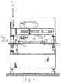
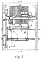
- Fig. 1 and 2 present an assembly robot cell provided with a system according to the invention for inspecting the leads of components, which automatically inspects each component before placing it on a circuit board to determine whether the component has any bent leads and whether it can be placed on the circuit board at all or whether it must be rejected and removed.
- the system automatically optimises the setting coordinates for the component if this is necessary due to a possible inaccuracy in the manner the component is held by the gripper or similar reasons.
- the assembly robot cell comprises a circuit board conveyor 21, which brings the circuit board 3 to an assembly station, where it is fixed in a predetermined precise position.
- the circuit board conveyor 21 is located in the working area of an overhead xyzw-portal robot 2 with four degrees of freedom.
- the coordinate system of the robot has been so defined that the x-direction is a horizontal direction corresponding to the direction of motion of the circuit board conveyor 21.
- the y-direction is a horizontal direction perpendicular to the x-direction.
- the z-direction is a vertical direction.
- the letter "w" in the term “xyzw-robot” refers to that the gripper is also rotatable about the z-axis.
- the assembly cell is provided with a number of component feed devices 20 located in the working area of the robot, each device feeding a specified component type.
- the robot can take one component at a time from the component feed device 20 and hold it in its grip.
- Disposed between the component feed device 20 and the circuit board conveyor 21 are inspection devices 8 according to the invention, the example in Fig. 2 comprising two such devices placed side by side.
- the inspection device 8 comprises a laser 9, from which a narrow laser beam 10 is directed in the x-direction at a light-sensitive detector 11 placed at a distance.
- the laser beam 10 is stationary.
- the diameter of the laser beam 10 is disposed to be equal to or slightly smaller than the thickness of the leads 4 to be inspected so that lead 4 is able to break the laser beam 10 and prevent its visibility to the detector 11 when the laser beam hits the lead.
- Fig. 3 presents the main components of the system as a simplified block diagram.
- the robot 2 and its control system constitute means 12 by which the component 1 can be moved in relation to the illuminating beam 10 so that the position of the component as a function of time is known, in the widthways and/or lengthways direction of the lead row 5, 6 so that the leads of the component 1 pass through the illuminating beam e.g. as illustrated in Fig. 4 - 7.
- the illuminating beam 10 reaches the light-sensitive detector 11, and when the laser beam comes to a lead row and falls on a lead, it cannot reach the light-sensitive detector. Further referring to Fig.
- the system comprises a first set of registering means 13, which register the impulse 14 produced by the light-sensitive detector 11 (see Fig. 10) as a result of the illuminating beam 10 being intercepted by the shadowing effect of a lead.
- the pulse consists of on/off states of the detector. When the laser beam is intercepted by a lead, the detector 11 goes to the 'off' state. When the laser beam again reaches the detector, the detector 11 goes to the 'on' state.
- the system comprises computing means 15, which compute the width l of the lead row and/or the distance e between adjacent lead rows on the basis of the starting and ending instants of the 'on' and 'off' states of the pulse obtained from the light-sensitive detector 11, the speed at which the component was moved by the robot through the laser beam being known.
- the system comprises comparing means 16, which compare the computed width l of the lead row and/or the computed distance e between adjacent lead rows to predetermined allowed values. The system instructs the robot to set the component on the circuit board if the width l of the lead row and/or the distance e between adjacent lead rows as computed from the measurement are/is within the allowed limit values.
- the system will instruct the robot to reject the component 1 and remove it without placing it on the circuit board 3 if the measured value/measured values differ from the allowed limit values.
- the system comprises a second set of registering means 17, designed to register from the robot control unit the supposed position coordinates of a specified lead of the component on the basis of the position data of the gripper 7 of the robot. Furthermore, the system comprises a second set of computing means 18, designed to compute the actual position coordinates of a specified lead on the basis of the pulse registered by the light-sensitive detector 11, corresponding to said specified lead, e.g. the first lead at the end of the component.
- the system comprises a second set of comparing means 19, designed to compare the supposed position coordinates of the lead to the computed actual position coordinates, and if they differ from each other, to calibrate the position coordinates of the lead of the component so as to make them correspond to the computed actual value to allow the insertion coordinates for the placement to be determined
- the computing and comparing means comprised in the system can be implemented as computer software in a computer controlling the robot.
- the implementation of one embodiment is described in more detail with reference to Figs. 15 and 16.
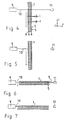
- Fig. 4 presents an elongated connector component 1 with a large number of leads 4, shown in the figure as being directed perpendicularly to the image plane.
- the leads 4 are arranged in three longitudinal rows 6, each comprising 24 leads.
- the rows 6 are so arranged that the leads are aligned with each other in the transverse direction, thus forming 24 transverse rows 5.
- both rows 5 and rows 6 have to be inspected.
- the 24 transverse rows 5 are being inspected and the component 1 is being moved through a laser beam 10. Between the rows 5, the laser beam can reach the detector 11, turning it to the 'on' state. In Fig. 5, the laser beam falls on a lead and the light-sensitive detector 11 is in the 'off' state.
- the longitudinal rows 6 are being inspected in a corresponding manner.
- Fig. 8 shows a magnified end view of the connector 1 in Fig. 4 - 7 and Fig. 9 presents the same connector as seen from its lead side.
- Line T represents the level at which the laser beam passes as the component 1 is being moved in relation to the beam.
- some leads protrude to one side, and these are detected because the widths l 1 and l 2 of the pulses 14 received from the detector 11 exceed the allowed limit values.
- the pulse for the row 6 on the right has a normal width, which means that the row contains no protruding leads. It is also possible to measure the interspaces e 1 and e 2 between the leads and compare them to allowed limit values.
- the 10 represents the output signal obtained from an encoder connected to the motor of the robot motion shaft, and this signal provides information regarding the position of the gripper of the robot. By comparing it with the pulse 14, the exact coordinates of a given lead are obtained, from which it is possible to compute the position of the lead and therefore the position of the component in relation to the gripper and correct the position coordinates of the component if this is necessary to ensure successful placement of the component.
- Fig. 11 illustrates an embodiment which uses only one laser beam 10, which is disposed in the x-direction between the component feeder 20 and the circuit board 3 to be assembled, extending across the route along which the component 1 is transferred.
- the robot is not shown in Fig. 11 - 14.
- the component 1 is taken by the robot first in a lengthways orientation in the y-direction through the laser beam 10, whereupon it is turned by the gripper through 90° in a horizontal plane, moved back and then taken again through the same laser beam 10 in the y-direction. If the component passes the inspection, then it will be placed in its specified location on the circuit board.
- Fig. 12 presents an embodiment corresponding to that in Fig. 2, differing from the embodiment in Fig. 11 in that the embodiment in Fig. 12 comprises two adjacent laser beams 10 disposed in the x-direction on the route of component transfer between the component feeder 20 and the circuit board 3 to be assembled.
- the component 1 is first taken in a lengthways orientation in the y-direction through a first illuminating beam, then turned horizontally through 90° and taken through a second illuminating beam, still in the y-direction.
- Fig. 13 presents an embodiment which uses two laser beams 10, one of which is oriented in the x-direction and the other in the y-direction, i.e. the beams are perpendicular to each other.
- the component 1 is moved in the y-direction through the laser beam oriented in the x-direction, and in the x-direction through the laser beam oriented in the y-direction.
- Fig. 14 presents an embodiment which uses two laser beams 10, one of which is oriented in the x-direction and the other in the y-direction, i.e. the beams are perpendicular to each other.
- the component 1 is moved simultaneously through both laser beams in both the x and y directions, so the direction of motion of the component is at an angle to the illuminating beam. This is the fastest embodiment.
- the system may comprise several laser beams 10 oriented in the y-direction. These beams can be disposed in suitable locations relative to the circuit board so that the inspection will involve as few turns as possible in the route of the component regardless of where in the circuit board area the component is to be placed.
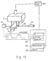
- Fig. 15 presents a system of a further embodiment of the invention.
- a narrow laser beam 10 is projected horizontally in front of the component feeders 20, as illustrated also in Fig. 2.
- the system comprises a laser source 9 and a light-sensitive detector 11 which are mounted in opposite sides of the machine frame.
- robot picks the component 1 up from the feeder 20 (see Fig. 2) and moves it to the circuit board (PCB board) 3, component leads 4 will cross the laser beam 10. Every time the lead 4 crosses the laser beam, a signal is generated.
- the light-sensitive detector 11, later called as laser receiver, is connected to a special PC-card later called as a LLC Card 22 ( L aser based L ead C home), which will record the current absolute (or incement) pulse-encoder counts from axis encoders 23 of the xyzw-robot whenever an edge is detected from the signal generated by the laser receiver 11. Based on this information a special PC-software calculates the position of the component leads related to the position of the gripper.
- a special PC-software calculates the position of the component leads related to the position of the gripper.
- motion controller 24 of the xyzw-robot 12 via ethernet link 25 (or via any other media) and motion controller 24 will then automatically correlate the possible position or orientation error before inserting the component onto PCB board.
- system needs some basic information about the structure of the component: lead count, lead width, offset between leads, the number of lead rows, height of the leads. This information will be given from the user interface (not shown) of the assembly robot cell as an expanded information about the feeders.
- System can be constructed by using one or several laser beams 10, as illustrated also in Figs. 2, 12, 13 and 14. If only one laser beam is used, system can check the lead count and position error only from one direction (i.e. y-error). To get both x and y errors, another laser beam is needed. Between first and second laser beams, component is then rotated 90 degrees, as illustrated in Fig. 12.
- component is slightly rotated so that leads which are supposed to be in line have slight (or if offset between leads in same row is big enough, leads from another line will be seen through offsets from first line) different width then. Based on this width information, rotation error of the component related to the gripper can be calculated.
- Fig. 16 presents a block diagram of said special PC card 22, called the LLC card, designed for signal handling and calculation in the system of the invention.
- Major task of the LLC-card is to capture the pulse encoder signal (without losing information) from the axis encoder 23 whenever an edge is detected in an incoming signal at the laser sensor input.
- LLC-card is equipped with a special circuitry, edge recognition and memory addressing circuitry 26 to detect these edges.
- Pulse counter circuits 27 are used for counting the pulses coming from axis encoders 23 so that the LLC-card 22 knows the actual position (absolute) of the moving axes.
- a current pulse encoder count is saved onto the dual port RAM memory 28 (which enables the read and write tasks to be made simultaneously) of the LLC-card. If laser sensor input changes, recording will be made into a different address.
- a bus interface logic 29 enables this information to be transferred from LLC-card into PC' s memory. Bus can be any common bus used in PC (ISA, PCI etc).
Landscapes
- Engineering & Computer Science (AREA)
- Manufacturing & Machinery (AREA)
- Microelectronics & Electronic Packaging (AREA)
- Operations Research (AREA)
- Physics & Mathematics (AREA)
- General Physics & Mathematics (AREA)
- Supply And Installment Of Electrical Components (AREA)
- Length Measuring Devices By Optical Means (AREA)
- Investigating Materials By The Use Of Optical Means Adapted For Particular Applications (AREA)
- Testing Or Measuring Of Semiconductors Or The Like (AREA)
- Length Measuring Devices With Unspecified Measuring Means (AREA)
Claims (31)
- Verfahren zum Prüfen eines Bauteils (1) mit Zuleitungen (4), um seine Eignung zur Bestückung im Zusammenhang mit einer automatischen Leiterplattenbestückung festzustellen, die unter Verwendung eines Bestückungsroboters (2) durchgeführt wird, bevor das Bauteil auf eine Leiterplatte aufgesetzt wird, wobei das Bauteil Zuleitungen aufweist, die in entsprechende Löcher in der Leiterplatte einzuführen sind, und der Roboter mit einem Greifer zum Festhalten des Bauteils versehen ist, bei dem
ein schmaler Beleuchtungsstrahl (10) auf einen lichtempfindlichen Detektor (11) gerichtet wird,
das Bauteil und der Beleuchtungsstrahl zueinander so bewegt werden, dass die Position als Funktion der Zeit bekannt ist, und so, dass die Zuleitungen des Bauteils durch den Beleuchtungsstrahl hindurchtreten, wobei der Beleuchtungsstrahl so den lichtempfindlichen Detektor (11) erreicht, wenn er zwischen Zuleitungen fällt, während, wenn er auf eine Zuleitung fällt, die Zuleitung verhindert, dass der Strahl den lichtempfindlichen Detektor erreicht,
dadurch gekennzeichnet, dass
der Impuls (14), der durch den lichtempfindlichen Detektor dadurch erzeugt wird, dass der Beleuchtungsstrahl durch die Abschattungswirkung der Zuleitung unterbrochen wird, registriert wird,
auf Basis des Impulses die Breite (l) der Zuleitung und/oder der Abstand (e) zwischen benachbarten Zuleitungen berechnet wird,
die Breite der Zuleitung und/oder der Abstand zwischen benachbarten Zuleitungen mit einem jeweiligen vorgegebenen zulässigen Grenzwert verglichen werden/wird, und
das Bauteil auf die Leiterplatte aufgesetzt wird, wenn die Breite und/oder der Abstand zwischen benachbarten Zuleitungen, die auf Basis der Messung berechnet werden/wird, innerhalb der zulässigen Grenzen liegen/liegt, oder, als Alternative dazu, das Bauteil ausgesondert und entfernt wird, ohne es auf die Leiterplatte auf zusetzen, wenn sich der gemessene Wert/die gemessenen Werte von den zulässigen Grenzwerten unterscheidet/unterscheiden. - Verfahren nach Anspruch 1, dadurch gekennzeichnet, dass das Bauteil eine Reihe von wenigstens zwei Zuleitungen hat und das Bauteil sowie der Beleuchtungsstrahl zueinander in der Richtung der Breite und/oder Länge der Reihe von Zuleitungen bewegt werden,
auf Basis des Impulses die Breite der Zuleitungsreihe und/oder der Abstand zwischen benachbarten Zuleitungsreihen berechnet werden/wird,
die Breite der Zuleitungsreihe und/oder der Abstand zwischen benachbarten Zuleitungsreihen mit einem jeweiligen vorgegebenen zulässigen Grenzwert verglichen werden/wird und
das Bauteil auf die Leiterplatte aufgesetzt wird, wenn die Breite und/oder der Abstand zwischen benachbarten Zuleitungsreihen, die auf Basis der Messung berechnet werden/wird, innerhalb der zulässigen Grenzen liegen/liegt, oder, als Altemative dazu, das Bauteil ausgesondert und entfernt wird, ohne es auf die Leiterplatte aufzusetzen, wenn sich der gemessene Wert/die gemessenen Werte von den zulässigen Grenzwerten unterscheidet/unterscheiden. - Verfahren nach Anspruch 2, dadurch gekennzeichnet, dass das Bauteil mittels eines Greifers eines xyzw-Roboters festgehalten und bewegt wird.
- Verfahren nach Anspruch 2 oder 3, dadurch gekennzeichnet, dass die Zuleitungsreihe des Bauteils geprüft wird, indem das Bauteil in Bezug auf einen stationären Beleuchtungsstrahl bewegt wird.
- Verfahren nach einem der Ansprüche 2 - 4, dadurch gekennzeichnet, dass das Bauteil in der Richtung der Breite und/oder der Länge der Reihe der Zuleitungen über den Beleuchtungsstrahl geführt wird.
- Verfahren nach einem der Ansprüche 2 - 5, dadurch gekennzeichnet, dass die Breite der Zuleitungsreihe und/oder der Abstand zwischen benachbarten Zuleitungsreihen auf Basis des Anfangs- und des Endmoments des Impulses berechnet werden/wird.
- Verfahren nach einem der Ansprüche 2-6. dadurch gekennzeichnet, dass der Beleuchtungsstrahl in einer horizontalen Ebene in der x-Richtung auf den lichtempfindlichen Detektor gerichtet wird.
- Verfahren nach einem der Ansprüche 2 - 7, dadurch gekennzeichnet, dass das Bauteil, bevor es durch den Beleuchtungsstrahl bewegt wird, gedreht wird, so dass die Zuleitungsreihe parallel zu dem Befeuchtungsstrahl wird.
- Verfahren nach einem der Ansprüche 2 - 8, dadurch gekennzeichnet, dass das Bauteil, bevor es durch den Beleuchtungsstrahl bewegt wird, an eine Position versetzt wird, an der die Zuleitungsreihe in einer horizontalen Ebene in der x-Richtung liegt, und das Bauteil in der y-Richtung durch den Beleuchtungsstrahl bewegt wird.
- Verfahren nach einem der Ansprüche 2 - 9, dadurch gekennzeichnet, dass das Bauteil, bevor es durch einen Beleuchtungsstrahl bewegt wird, an eine Position versetzt wird, an der die Zuleitungsreihe in einer horizontalen Ebene in der y-Richtung liegt, die senkrecht zu der x-Richtung ist, und das Bauteil in der y-Richtung durch den Beleuchtungsstrahl bewegt wird.
- Verfahren nach einem der Ansprüche 2-10, dadurch gekennzeichnet, dass das Bauteil gleichzeitig in der x- und der y-Richtung durch einen Beleuchtungsstrahl bewegt wird.
- Verfahren nach einem der Ansprüche 2 - 11, dadurch gekennzeichnet, dass das Bauteil, bevor es durch einen Beleuchtungsstrahl bewegt wird, in der z-Richtung, die senkrecht zu der x- und der y-Richtung ist, an einer Position ausgerichtet wird, an der die Ebene des Beleuchtungsstrahls die Zuleitungen an ihre freien Enden angrenzend schneidet.
- Verfahren nach einem der Ansprüche 2 - 12, dadurch gekennzeichnet, dass die Zuleitungsreihe des Bauteils geprüft wird, indem das Bauteil durch einen horizontalen Beleuchtungsstrahl bewegt wird, der vorzugsweise in der x-Richtung ausgerichtet ist, und zwar zuerst in einer Richtung, und dann das Bauteil horizontal um 90° gedreht wird und dann erneut durch den gleichen Beleuchtungsstrahl bewegt wird.
- Verfahren nach einem der Ansprüche 2 -12, dadurch gekennzeichnet, dass zwei parallele Beleuchtungsstrahlen, die in einem Abstand zueinander angeordnet und vorzugsweise in der x-Richtung ausgerichtet sind, vorhanden sind, wobei die Zuleitungsreihe des Bauteils unter Verwendung eines ersten Befeuchtungsstrahls geprüft wird, das Bauteil horizontal um 90° gedreht wird und die Zuleitungsreihe des Bauteils unter Verwendung eines zweiten Beleuchtungsstrahls geprüft wird.
- Verfahren nach einem der Ansprüche 2 - 12, dadurch gekennzeichnet, dass zwei Beleuchtungsstrahlen senkrecht zueinander vorhanden sind, wobei die Zuleitungsreihe geprüft wird, indem das Bauteil durch beide Beleuchtungsstrahlen bewegt wird.
- Verfahren nach einem der Ansprüche 2 - 15, dadurch gekennzeichnet, dass, während das Bauteil durch einen Beleuchtungsstrahl bewegt wird,
die angenommenen Positionskoordinaten einer angegebenen Zuleitung des Bauteils von der Steuereinheit des Roboters auf Basis von Positionsdaten für den Greifer des Roboters registriert werden,
auf Basis des Impulses, der durch den lichtempfindlichen Detektor registriert wird, und entsprechend der angegebenen Zuleitung die tatsächlichen Positionskoordinaten der angegebenen Zuleitung berechnet werden, und
die angenommenen Positionskoordinaten der Zuleitung mit den berechneten tatsächlichen Positionskoordinaten verglichen werden, und, wenn sie sich voneinander unterscheiden, die Positionskoordinaten der Zuleitung des Bauteils so kalibriert werden, dass sie dem berechneten tatsächlichen Wert entsprechen, um die Einführkoordinaten für das Aufsetzen bestimmen zu können. - Verfahren nach einem der Ansprüche 2 - 6, dadurch gekennzeichnet, dass der Beleuchtungsstrahl unter Verwendung eines Lasers erzeugt wird.
- System zum Prüfen eines Bauteils (1) mit Zuleitungen, um seine Eignung zur Bestückung im Zusammenhang mit automatischer Leiterplattenbestückung zu bestimmen, die unter Verwendung eines Bestückungsroboters (2) durchgeführt wird, bevor das Bauteil auf eine Leiterplatte (3) aufgesetzt wird, wobei das Bauteil eine Reihe (5, 6) von wenigstens zwei Zuleitungen (4) hat, die in entsprechende Löcher in der Leiterplatte einzuführen sind, der Roboter mit einem Greifer (7) zum Festhalten des Bauteils versehen ist und das System umfasst:- eine Prüfvorrichtung (8), die eine Lichtquelle (9) zur Erzeugung eines Beleuchtungsstrahls (10) und einen lichtempfindlichen Detektor (11) umfasst, auf den der Beleuchtungsstrahl gerichtet wird,- eine Einrichtung (12) zum Bewegen des Bauteils (1) und des Beleuchtungsstrahls (10) relativ zueinander so, dass die Position als eine Funktion der Zeit bekannt ist, und so, dass die Zuleitungen des Bauteils durch den Beleuchtungsstrahl hindurchtreten, wobei der Beleuchtungsstrahl so den lichtempfindlichen Detektor erreicht, wenn er zwischen Zuleitungen fällt, während, wenn er auf Zuleitungen fällt, die Zuleitungen einen Schatten werfen und verhindern, dass der Strahl den lichtempfindlichen Detektor erreicht,
gekennzeichnet durch:- eine Einrichtung (13) zum Registrieren des Impulses (14), der durch den lichtempfindlichen Detektor dadurch erzeugt wird, dass der Beleuchtungsstrahl durch den Abschattungseffekt der Zuleitungen unterbrochen wird,- eine Einrichtung (15) zum Berechnen der Breite (l) der Zuleitungsreihe und/oder des Abstandes (e) zwischen benachbarten Zuleitungsreihen auf Basis des Impulses, und- eine Einrichtung (16) zum Vergleichen der berechneten Breite der Zuleitungsreihe und/oder des berechneten Abstandes zwischen benachbarten Zuleitungsreihen mit einem angegebenen zulässigen Grenzwert. - System nach Anspruch 18, dadurch gekennzeichnet, dass das System umfasst:- eine Einrichtung (17), die so eingerichtet ist, dass sie die angenommenen Positionskoordinaten einer angegebenen Zuleitung des Bauteils von der Steuereinheit eines Roboters auf Basis von Positionsdaten für den Greifer des Roboters registriert,- eine Einrichtung (18), die so eingerichtet ist, dass sie auf Basis des Impulses, der durch den lichtempfindlichen Detektor registriert wird, und entsprechend der angegebenen Zuleitung die tatsächlichen Positionskoordinaten der angegebenen Zuleitung berechnet, und- eine Einrichtung (19), die so eingerichtet ist, dass sie die angenommenen Positionskoordinaten der Zuleitung mit den berechneten tatsächlichen Positionskoordinaten vergleicht, und, wenn sie sich voneinander unterscheiden, die Positionskoordinaten der Zuleitung des Bauteils so kalibriert, dass sie dem berechneten tatsächlichen Wert entsprechen, so dass die Einführkoordinaten für das Aufsetzen bestimmt werden können.
- System nach Anspruch 18 oder 19, dadurch gekennzeichnet, dass die Einrichtung (12) zum Bewegen des Bauteils (1) so angeordnet ist, dass sie das Bauteil in der Breiten- und/oder Längsrichtung der Zuleitungsreihe (5, 6) bewegt.
- System nach einem der Ansprüche 8 - 20, dadurch gekennzeichnet, dass die Prüfvorrichtung (8) fest angebracht ist und der Roboter (2) so eingerichtet worden ist, dass er das Bauteil in Bezug auf den Beleuchtungsstraht (10) bewegt.
- System nach einem der Ansprüche 18 - 21, dadurch gekennzeichnet, dass die Lichtquelle (9) so angeordnet ist, dass der Beleuchtungsstrahl (10) horizontal ist.
- System nach einem der Ansprüche 18 - 22, dadurch gekennzeichnet, dass der Bestückungsroboter ein xyzw-Roboter ist.
- System nach einem der Ansprüche 18 - 23, dadurch gekennzeichnet, dass die Lichtquelle (9) so angeordnet ist, dass der Beleuchtungsstrahl (10) parallel zu der x-Richtung in dem Koordinatensystem des Roboters ist, während die Leiterplatte (3) in der xy-Ebene liegt.
- System nach einem der Ansprüche 18 - 24, dadurch gekennzeichnet, dass das System zwei benachbarte Prüfvorrichtungen (8) umfasst, wobei die Beleuchtungsstrahlen (10) parallel zueinander und voneinander beabstandet sind.
- System nach einem der Ansprüche 18 - 25, dadurch gekennzeichnet, dass das System zwei Prüfvorrichtungen (8) umfasst, wobei die Beleuchtungsstrahlen (10) senkrecht zueinander sind.
- System nach einem der Ansprüche 18 - 26, dadurch gekennzeichnet, dass wenigstens eine Prüfvorrichtung (8) zwischen der Bauteil-Beschickungsvorrichtung (20) und der Leiterplatten-Fördereinrichtung (21) angeordnet ist.
- System nach einem der Ansprüche 18 - 27, dadurch gekennzeichnet, dass die Prüfvorrichtung/Prüfvorrichtungen (8) in Bezug auf die Leiterplatten-Bestückungsstation so angeordnet ist/sind, dass die Prüfung von Zuleitungen während der Roboterbewegung zum Überführen des Bauteils zwischen der Bauteil-Beschickungsstation (20) und der Leiterplatte im Wesentlichen ohne Unterbrechung der Überführungsbewegung und im Wesentlichen ohne Abweichung von dem Überführungsweg zwischen der Bauteil-Beschickungsstation und der Bestückungsstation durchgeführt werden kann.
- System nach einem der Ansprüche 18 - 28, dadurch gekennzeichnet, dass die Lichtquelle (9) ein Laser ist.
- System nach einem der Ansprüche 18-29, dadurch gekennzeichnet, dass der Durchmesser des Beleuchtungsstrahls (10) kleiner ist als die Dicke der Zuleitung (4) oder genauso groß wie diese.
- System nach einem der Ansprüche 18 - 30, dadurch gekennzeichnet, dass der Durchmesser des Beleuchtungsstrahls (10) in der Größenordnung von 0,1 mm liegt.
Applications Claiming Priority (3)
| Application Number | Priority Date | Filing Date | Title |
|---|---|---|---|
| US09/329,541 US6222629B1 (en) | 1999-06-10 | 1999-06-10 | Procedure and system for inspecting a component with leads to determine its fitness for assembly |
| US329541 | 1999-06-10 | ||
| PCT/FI2000/000527 WO2000078116A1 (en) | 1999-06-10 | 2000-06-12 | Procedure and system for inspecting a component with leads to determine its fitness for assembly |
Publications (3)
| Publication Number | Publication Date |
|---|---|
| EP1106043A1 EP1106043A1 (de) | 2001-06-13 |
| EP1106043B1 true EP1106043B1 (de) | 2006-03-15 |
| EP1106043B9 EP1106043B9 (de) | 2006-06-28 |
Family
ID=23285888
Family Applications (1)
| Application Number | Title | Priority Date | Filing Date |
|---|---|---|---|
| EP00936922A Expired - Lifetime EP1106043B9 (de) | 1999-06-10 | 2000-06-12 | Verfahren und system zur inspektion eines bauteils mit anschlüssen und zum erfassen der korrekten bestückungsposition |
Country Status (6)
| Country | Link |
|---|---|
| US (1) | US6222629B1 (de) |
| EP (1) | EP1106043B9 (de) |
| AT (1) | ATE320702T1 (de) |
| AU (1) | AU5224100A (de) |
| DE (1) | DE60026701D1 (de) |
| WO (1) | WO2000078116A1 (de) |
Families Citing this family (10)
| Publication number | Priority date | Publication date | Assignee | Title |
|---|---|---|---|---|
| WO2002046713A2 (en) * | 2000-12-08 | 2002-06-13 | Cyberoptics Corporation | Automated system with improved height sensing |
| CN101755497B (zh) * | 2007-08-28 | 2012-03-14 | 松下电器产业株式会社 | 元件放置设备 |
| JP4872854B2 (ja) * | 2007-08-28 | 2012-02-08 | パナソニック株式会社 | 部品実装装置 |
| JP4998148B2 (ja) * | 2007-08-28 | 2012-08-15 | パナソニック株式会社 | 部品実装装置 |
| KR101292570B1 (ko) * | 2008-12-31 | 2013-08-12 | 엘지디스플레이 주식회사 | 액정표시장치의 변형 검사시스템 |
| CN106797714B (zh) * | 2014-10-03 | 2019-05-21 | 株式会社富士 | 元件装配系统及元件装配装置的异常停止诊断方法 |
| US10932401B2 (en) * | 2015-07-23 | 2021-02-23 | Fuji Corporation | Component mounting machine |
| JP6154456B2 (ja) * | 2015-12-24 | 2017-06-28 | Juki株式会社 | 電子部品実装方法及び電子部品実装装置 |
| JP6829946B2 (ja) * | 2016-04-28 | 2021-02-17 | 川崎重工業株式会社 | 部品検査装置および方法 |
| US10802475B2 (en) * | 2018-07-16 | 2020-10-13 | Elite Robotics | Positioner for a robotic workcell |
Family Cites Families (6)
| Publication number | Priority date | Publication date | Assignee | Title |
|---|---|---|---|---|
| US5278634A (en) * | 1991-02-22 | 1994-01-11 | Cyberoptics Corporation | High precision component alignment sensor system |
| US5309223A (en) * | 1991-06-25 | 1994-05-03 | Cyberoptics Corporation | Laser-based semiconductor lead measurement system |
| US5805722A (en) | 1993-11-22 | 1998-09-08 | Cognex Corporation | Method and apparatus for locating, inspecting, and placing large leaded devices |
| US5559727A (en) * | 1994-02-24 | 1996-09-24 | Quad Systems Corporation | Apparatus and method for determining the position of a component prior to placement |
| WO1997040657A1 (en) * | 1996-04-23 | 1997-10-30 | Matsushita Electric Industrial Co., Ltd. | Electronic component mounting apparatus |
| JP3296968B2 (ja) * | 1996-04-26 | 2002-07-02 | ヤマハ発動機株式会社 | 基準位置決定方法 |
-
1999
- 1999-06-10 US US09/329,541 patent/US6222629B1/en not_active Expired - Fee Related
-
2000
- 2000-06-12 AU AU52241/00A patent/AU5224100A/en not_active Abandoned
- 2000-06-12 EP EP00936922A patent/EP1106043B9/de not_active Expired - Lifetime
- 2000-06-12 WO PCT/FI2000/000527 patent/WO2000078116A1/en not_active Ceased
- 2000-06-12 DE DE60026701T patent/DE60026701D1/de not_active Expired - Lifetime
- 2000-06-12 AT AT00936922T patent/ATE320702T1/de not_active IP Right Cessation
Also Published As
| Publication number | Publication date |
|---|---|
| AU5224100A (en) | 2001-01-02 |
| EP1106043B9 (de) | 2006-06-28 |
| DE60026701D1 (de) | 2006-05-11 |
| US6222629B1 (en) | 2001-04-24 |
| WO2000078116A1 (en) | 2000-12-21 |
| ATE320702T1 (de) | 2006-04-15 |
| EP1106043A1 (de) | 2001-06-13 |
Similar Documents
| Publication | Publication Date | Title |
|---|---|---|
| US20050117797A1 (en) | Pick and place machine with improved component placement inspection | |
| EP0222072B1 (de) | Verfahren zur Plazierung eines oberflächenmontierten Teiles und eine Vorrichtung dazu | |
| EP0897657B1 (de) | Elektronische bauteile bestückungsvorrichtung | |
| US20120327215A1 (en) | High speed optical sensor inspection system | |
| KR0185688B1 (ko) | 고정밀 부품 얼라인먼트 센서 시스템 | |
| US7746481B2 (en) | Method for measuring center of rotation of a nozzle of a pick and place machine using a collimated laser beam | |
| US9523735B2 (en) | Electrical test system with vision-guided alignment | |
| EP1106043B9 (de) | Verfahren und system zur inspektion eines bauteils mit anschlüssen und zum erfassen der korrekten bestückungsposition | |
| US20090135251A1 (en) | Method and apparatus for evaluating a component pick action in an electronics assembly machine | |
| JPS63180111A (ja) | 自動位置決めシステム | |
| US20100295935A1 (en) | On-head component alignment using multiple area array image detectors | |
| JP2003264396A (ja) | 部品載置方法 | |
| US9581640B2 (en) | Vision-guided alignment method | |
| US6229608B1 (en) | Procedure and system for inspecting a component with leads to determine its fitness for assembly | |
| US20050268460A1 (en) | Component feeder exchange diagnostic tool | |
| US20060016066A1 (en) | Pick and place machine with improved inspection | |
| EP0206709A2 (de) | Automatische optische Überprüfung für gedruckte Schaltungen | |
| US9535116B2 (en) | Electrical test method with vision-guided alignment | |
| JP3725993B2 (ja) | 電子部品実装回路基板の検査方法及びその装置 | |
| US9557374B2 (en) | Vision-guided alignment system | |
| JP2012252003A (ja) | 高速光学センサ検査システム | |
| JPS62240871A (ja) | プリント板測定装置のプロービング方法 | |
| WO2006125102A1 (en) | Method and apparatus for evaluating a component pick action in an electronics assembly machine | |
| JP5271654B2 (ja) | 電子部品実装装置 | |
| JPH07104136B2 (ja) | 端子の傾き検出方法 |
Legal Events
| Date | Code | Title | Description |
|---|---|---|---|
| PUAI | Public reference made under article 153(3) epc to a published international application that has entered the european phase |
Free format text: ORIGINAL CODE: 0009012 |
|
| 17P | Request for examination filed |
Effective date: 20010117 |
|
| AK | Designated contracting states |
Kind code of ref document: A1 Designated state(s): AT BE CH CY DE DK ES FI FR GB GR IE IT LI LU MC NL PT |
|
| AX | Request for extension of the european patent |
Free format text: AL;LT;LV;MK;RO;SI |
|
| GRAP | Despatch of communication of intention to grant a patent |
Free format text: ORIGINAL CODE: EPIDOSNIGR1 |
|
| GRAS | Grant fee paid |
Free format text: ORIGINAL CODE: EPIDOSNIGR3 |
|
| GRAA | (expected) grant |
Free format text: ORIGINAL CODE: 0009210 |
|
| AK | Designated contracting states |
Kind code of ref document: B1 Designated state(s): AT BE CH CY DE DK ES FI FR GB GR IE IT LI LU MC NL PT |
|
| PG25 | Lapsed in a contracting state [announced via postgrant information from national office to epo] |
Ref country code: IT Free format text: LAPSE BECAUSE OF FAILURE TO SUBMIT A TRANSLATION OF THE DESCRIPTION OR TO PAY THE FEE WITHIN THE PRESCRIBED TIME-LIMIT;WARNING: LAPSES OF ITALIAN PATENTS WITH EFFECTIVE DATE BEFORE 2007 MAY HAVE OCCURRED AT ANY TIME BEFORE 2007. THE CORRECT EFFECTIVE DATE MAY BE DIFFERENT FROM THE ONE RECORDED. Effective date: 20060315 Ref country code: FI Free format text: LAPSE BECAUSE OF FAILURE TO SUBMIT A TRANSLATION OF THE DESCRIPTION OR TO PAY THE FEE WITHIN THE PRESCRIBED TIME-LIMIT Effective date: 20060315 Ref country code: AT Free format text: LAPSE BECAUSE OF FAILURE TO SUBMIT A TRANSLATION OF THE DESCRIPTION OR TO PAY THE FEE WITHIN THE PRESCRIBED TIME-LIMIT Effective date: 20060315 Ref country code: BE Free format text: LAPSE BECAUSE OF FAILURE TO SUBMIT A TRANSLATION OF THE DESCRIPTION OR TO PAY THE FEE WITHIN THE PRESCRIBED TIME-LIMIT Effective date: 20060315 Ref country code: LI Free format text: LAPSE BECAUSE OF FAILURE TO SUBMIT A TRANSLATION OF THE DESCRIPTION OR TO PAY THE FEE WITHIN THE PRESCRIBED TIME-LIMIT Effective date: 20060315 Ref country code: CH Free format text: LAPSE BECAUSE OF FAILURE TO SUBMIT A TRANSLATION OF THE DESCRIPTION OR TO PAY THE FEE WITHIN THE PRESCRIBED TIME-LIMIT Effective date: 20060315 Ref country code: NL Free format text: LAPSE BECAUSE OF FAILURE TO SUBMIT A TRANSLATION OF THE DESCRIPTION OR TO PAY THE FEE WITHIN THE PRESCRIBED TIME-LIMIT Effective date: 20060315 |
|
| REG | Reference to a national code |
Ref country code: CH Ref legal event code: EP Ref country code: GB Ref legal event code: FG4D |
|
| RAP2 | Party data changed (patent owner data changed or rights of a patent transferred) |
Owner name: CENCORP OYJ |
|
| REG | Reference to a national code |
Ref country code: GB Ref legal event code: ERR Free format text: NOTIFICATION HAS NOW BEEN RECEIVED FROM THE EUROPEAN PATENT OFFICE THAT THE CORRECT NAME IS: CENCORP OYJ THIS CORRECTION WILL BE PUBLISHED IN THE EUROPEAN PATENT BULLETIN 06/14 DATED 20060405 |
|
| REG | Reference to a national code |
Ref country code: IE Ref legal event code: FG4D |
|
| REF | Corresponds to: |
Ref document number: 60026701 Country of ref document: DE Date of ref document: 20060511 Kind code of ref document: P |
|
| NLT2 | Nl: modifications (of names), taken from the european patent patent bulletin |
Owner name: CENCORP OYJ Effective date: 20060405 |
|
| PG25 | Lapsed in a contracting state [announced via postgrant information from national office to epo] |
Ref country code: IE Free format text: LAPSE BECAUSE OF NON-PAYMENT OF DUE FEES Effective date: 20060612 |
|
| PG25 | Lapsed in a contracting state [announced via postgrant information from national office to epo] |
Ref country code: DK Free format text: LAPSE BECAUSE OF FAILURE TO SUBMIT A TRANSLATION OF THE DESCRIPTION OR TO PAY THE FEE WITHIN THE PRESCRIBED TIME-LIMIT Effective date: 20060615 Ref country code: GB Free format text: LAPSE BECAUSE OF NON-PAYMENT OF DUE FEES Effective date: 20060615 |
|
| PG25 | Lapsed in a contracting state [announced via postgrant information from national office to epo] |
Ref country code: DE Free format text: LAPSE BECAUSE OF FAILURE TO SUBMIT A TRANSLATION OF THE DESCRIPTION OR TO PAY THE FEE WITHIN THE PRESCRIBED TIME-LIMIT Effective date: 20060617 |
|
| PG25 | Lapsed in a contracting state [announced via postgrant information from national office to epo] |
Ref country code: ES Free format text: LAPSE BECAUSE OF FAILURE TO SUBMIT A TRANSLATION OF THE DESCRIPTION OR TO PAY THE FEE WITHIN THE PRESCRIBED TIME-LIMIT Effective date: 20060626 |
|
| PG25 | Lapsed in a contracting state [announced via postgrant information from national office to epo] |
Ref country code: MC Free format text: LAPSE BECAUSE OF NON-PAYMENT OF DUE FEES Effective date: 20060630 |
|
| PG25 | Lapsed in a contracting state [announced via postgrant information from national office to epo] |
Ref country code: PT Free format text: LAPSE BECAUSE OF FAILURE TO SUBMIT A TRANSLATION OF THE DESCRIPTION OR TO PAY THE FEE WITHIN THE PRESCRIBED TIME-LIMIT Effective date: 20060816 |
|
| NLV1 | Nl: lapsed or annulled due to failure to fulfill the requirements of art. 29p and 29m of the patents act | ||
| REG | Reference to a national code |
Ref country code: CH Ref legal event code: PL |
|
| PLBE | No opposition filed within time limit |
Free format text: ORIGINAL CODE: 0009261 |
|
| STAA | Information on the status of an ep patent application or granted ep patent |
Free format text: STATUS: NO OPPOSITION FILED WITHIN TIME LIMIT |
|
| 26N | No opposition filed |
Effective date: 20061218 |
|
| GBPC | Gb: european patent ceased through non-payment of renewal fee |
Effective date: 20060615 |
|
| EN | Fr: translation not filed | ||
| PG25 | Lapsed in a contracting state [announced via postgrant information from national office to epo] |
Ref country code: GR Free format text: LAPSE BECAUSE OF FAILURE TO SUBMIT A TRANSLATION OF THE DESCRIPTION OR TO PAY THE FEE WITHIN THE PRESCRIBED TIME-LIMIT Effective date: 20060616 Ref country code: FR Free format text: LAPSE BECAUSE OF FAILURE TO SUBMIT A TRANSLATION OF THE DESCRIPTION OR TO PAY THE FEE WITHIN THE PRESCRIBED TIME-LIMIT Effective date: 20070309 |
|
| PG25 | Lapsed in a contracting state [announced via postgrant information from national office to epo] |
Ref country code: LU Free format text: LAPSE BECAUSE OF NON-PAYMENT OF DUE FEES Effective date: 20060612 |
|
| PG25 | Lapsed in a contracting state [announced via postgrant information from national office to epo] |
Ref country code: CY Free format text: LAPSE BECAUSE OF FAILURE TO SUBMIT A TRANSLATION OF THE DESCRIPTION OR TO PAY THE FEE WITHIN THE PRESCRIBED TIME-LIMIT Effective date: 20060315 Ref country code: FR Free format text: LAPSE BECAUSE OF FAILURE TO SUBMIT A TRANSLATION OF THE DESCRIPTION OR TO PAY THE FEE WITHIN THE PRESCRIBED TIME-LIMIT Effective date: 20060315 |