EP1106312A2 - Maschine zum Schneiden von Lebensmitteln - Google Patents
Maschine zum Schneiden von Lebensmitteln Download PDFInfo
- Publication number
- EP1106312A2 EP1106312A2 EP00124025A EP00124025A EP1106312A2 EP 1106312 A2 EP1106312 A2 EP 1106312A2 EP 00124025 A EP00124025 A EP 00124025A EP 00124025 A EP00124025 A EP 00124025A EP 1106312 A2 EP1106312 A2 EP 1106312A2
- Authority
- EP
- European Patent Office
- Prior art keywords
- cutting
- section
- cross
- machine
- knife
- Prior art date
- Legal status (The legal status is an assumption and is not a legal conclusion. Google has not performed a legal analysis and makes no representation as to the accuracy of the status listed.)
- Granted
Links
Images





Classifications
-
- B—PERFORMING OPERATIONS; TRANSPORTING
- B26—HAND CUTTING TOOLS; CUTTING; SEVERING
- B26D—CUTTING; DETAILS COMMON TO MACHINES FOR PERFORATING, PUNCHING, CUTTING-OUT, STAMPING-OUT OR SEVERING
- B26D1/00—Cutting through work characterised by the nature or movement of the cutting member or particular materials not otherwise provided for; Apparatus or machines therefor; Cutting members therefor
- B26D1/01—Cutting through work characterised by the nature or movement of the cutting member or particular materials not otherwise provided for; Apparatus or machines therefor; Cutting members therefor involving a cutting member which does not travel with the work
- B26D1/12—Cutting through work characterised by the nature or movement of the cutting member or particular materials not otherwise provided for; Apparatus or machines therefor; Cutting members therefor involving a cutting member which does not travel with the work having a cutting member moving about an axis
- B26D1/25—Cutting through work characterised by the nature or movement of the cutting member or particular materials not otherwise provided for; Apparatus or machines therefor; Cutting members therefor involving a cutting member which does not travel with the work having a cutting member moving about an axis with a non-circular cutting member
- B26D1/26—Cutting through work characterised by the nature or movement of the cutting member or particular materials not otherwise provided for; Apparatus or machines therefor; Cutting members therefor involving a cutting member which does not travel with the work having a cutting member moving about an axis with a non-circular cutting member moving about an axis substantially perpendicular to the line of cut
- B26D1/28—Cutting through work characterised by the nature or movement of the cutting member or particular materials not otherwise provided for; Apparatus or machines therefor; Cutting members therefor involving a cutting member which does not travel with the work having a cutting member moving about an axis with a non-circular cutting member moving about an axis substantially perpendicular to the line of cut and rotating continuously in one direction during cutting
-
- B—PERFORMING OPERATIONS; TRANSPORTING
- B26—HAND CUTTING TOOLS; CUTTING; SEVERING
- B26D—CUTTING; DETAILS COMMON TO MACHINES FOR PERFORATING, PUNCHING, CUTTING-OUT, STAMPING-OUT OR SEVERING
- B26D3/00—Cutting work characterised by the nature of the cut made; Apparatus therefor
- B26D3/18—Cutting work characterised by the nature of the cut made; Apparatus therefor to obtain cubes or the like
-
- B—PERFORMING OPERATIONS; TRANSPORTING
- B26—HAND CUTTING TOOLS; CUTTING; SEVERING
- B26D—CUTTING; DETAILS COMMON TO MACHINES FOR PERFORATING, PUNCHING, CUTTING-OUT, STAMPING-OUT OR SEVERING
- B26D7/00—Details of apparatus for cutting, cutting-out, stamping-out, punching, perforating, or severing by means other than cutting
- B26D7/01—Means for holding or positioning work
-
- B—PERFORMING OPERATIONS; TRANSPORTING
- B26—HAND CUTTING TOOLS; CUTTING; SEVERING
- B26D—CUTTING; DETAILS COMMON TO MACHINES FOR PERFORATING, PUNCHING, CUTTING-OUT, STAMPING-OUT OR SEVERING
- B26D7/00—Details of apparatus for cutting, cutting-out, stamping-out, punching, perforating, or severing by means other than cutting
- B26D7/06—Arrangements for feeding or delivering work of other than sheet, web, or filamentary form
- B26D7/0641—Arrangements for feeding or delivering work of other than sheet, web, or filamentary form using chutes, hoppers, magazines
Definitions
- the invention relates to a machine for cutting food into slices, strips or cubes with an insertion shaft for the material to be cut, which is contained therein by means of a feed device towards an over an outlet cross section of the insertion shaft extending cutting device can be advanced, the gate knife and a rotating cutting knife has, the inner cross section of the insertion shaft by change the position of at least one of its longitudinal walls can be changed.
- Such a machine is known for example from DE 44 44 506 Cl.
- a vertical one Longitudinal wall of the insertion shaft called a magazine is with the help of a pre-press ram slidable in the transverse direction of the magazine in order to pre-compress the material to be cut to achieve after its introduction into the insertion shaft.
- the opposite vertical Longitudinal wall can be detached from a bottom part of the insertion shaft and can be removed from the machine altogether removable.
- the state of the art also includes gate cutting machines in which the internal cross section of the insertion shaft with the help of a reducing part in the form of, for example, one further longitudinal wall can be reduced. Such a reduction is then appropriate if, for example, due to a smaller strand of material in its cross-sectional dimensions only part of the total cross section of the gate is to be used.
- a reducing part in the form of, for example, one further longitudinal wall can be reduced.
- cross-sectional shape and size of the crop strand to be cut can also be included in the Use gaps between the gate knives in the areas of the closure elements, that would not be affected by the crop strand to be cut anyway. Because of The large number of possible cross-sectional shapes is a correspondingly large number of reducing elements and filling elements required.
- the invention is based on the object of an inexpensively producible cube cutting machine to propose with a relatively small gate cross-section, with which also Cut sliced goods such as chops, roulades or steaks without problems to let.
- this object is achieved according to the invention solved in that the outlet cross section of the insertion shaft over a in Gate cutting operation effective cutting cross-section can be enlarged.
- the invention makes use of the knowledge that, depending on the type of problem to be solved Cutting task on one and the same machine with different cross-sections both the insertion shaft itself and its outlet opening are being worked on. While in the generally known creel cutting machines by reducing the Shaft cross-section and the effective gate cross-section to adapt to the cross-sections smaller strands of material is possible, it is based on a machine with a small gate cross-section not possible to slice large-volume products such as Use chops, roulades or steaks.
- this is the one according to the invention
- Possibility of enlarging the outlet cross section beyond the gate cross section indispensable to both as an economically producible cube cutter also have the option of cutting slices on a piece of snow, whose cross-sectional dimensions exceed those of the gate knife device.
- the cross section of the Insertion chute and the then existing outlet opening in a cost-effective manner Generate strips or cubes of cut material. From the same machine can be changed the position of a longitudinal wall and simultaneous enlargement of the outlet cross section even large-volume ones on the internal cross-section realized in the insertion shaft Pick up the material to be cut and convey it to the cutting device, with which the slices then can be cut off.
- the gate knife device is before the enlargement of the Removed internal cross section and the outlet cross section of the insertion shaft.
- the outlet cross section and the inner cross section of the insertion shaft are preferably in can be enlarged to the same extent.
- An embodiment of the invention is that a longitudinal wall of the insertion shaft of removable from the machine and another longitudinal wall in a different position with the machine is connectable.
- two or more can be defined Realize inside and outlet cross sections.
- two different ones Sufficient cross-sections to choose from, since it is not harmful to the slicer, if the shaft cross-section is not completely filled with the material strand to be cut is.
- a further development of the machine according to the invention is that an L-shaped Reducing part can be removed from a front wall of the machine, the L-legs with a small exit cross-section of the insertion shaft with its inner edges and with its outer edges define a large outlet cross section. While removing the reducer the large outlet cross-section is available for the disc cutting operation, is excluded in the cube cutting operation with built-in reducer that from the Product delivery side in the area of the cutting knife is reached.
- a longitudinal wall with at least an end groove is provided, in which a connected to a machine housing Engages web.
- a longitudinal wall has a longitudinal slot for the introduction of a Separating slide has a counter knife in the form of a recess in one opposing longitudinal wall cooperates, can be done on the one hand when cutting gates a good filling of the insertion shaft and on the other hand a secure pressure build-up when advancing ensure the material to be cut.
- an area above the recess can be filled with a cover element such that the surface of the formed longitudinal wall extends in a single plane.
- An upper side of the cover element advantageously forms a guide surface for one horizontally displaceable loading lid, which is a safety-relevant component prevents unintentional intervention in the insertion slot while the cutting device is running.
- the object underlying the invention is also achieved by a machine Slicing food into slices, strips or cubes is solved using an insertion slot for the material to be cut, which is in it in the direction of a feed device on a cutting device extending over an outlet cross section of the insertion shaft can be advanced, which has a gate knife and a rotating cutting knife, the cutting knife according to the invention about at least one further axis of rotation is rotatable, which runs parallel to the axis of rotation effective in the creel cutting operation and in Distance to this is arranged.
- the arrangement of the axis of rotation on a diagonal is typical for frame cutting machines through the corner points of the generally square cutting cross section of the gate device.
- This arrangement of the axis of rotation results on the one hand from the extension of the respective one Gate drives in the direction of an imaginary extension of the gate knife, so that a approximately cruciform area with the gate cross section in the center not for driving the Clipping knife is available.
- the arrangement of the axis of rotation of the Cutting knife on a diagonal through a square gate cross section therefore particularly favorable because then the pressure load acting laterally on the gate knife evenly on the two groups of gate knives arranged perpendicular to each other is distributed.
- Such an arrangement of the axis of rotation of the cutting knife is in the disk cutting operation however unfavorable because of a very large component of the radial feed rate not to press the strand of material to be cut against its contact surface, but to one lateral displacement of the same or even leads to a lift off the support surface.
- Knife gate is arranged, so that the cutting conditions for the Slice cutting operation can be optimized.
- the cutting knife can be attached to the drive shaft of a knife gate, leaves the position of the axis of rotation of the cutting knife also in disk cutting mode improve comparatively simple means considerably.
- the axis of rotation of the cutting knife can namely be arranged in this case so that the radially acting component of the cutting speed vector to a much greater extent to a contact pressure of the crop strand leads to the bottom of the insertion shaft.
- the transfer of Axis of rotation of the cutting knife to reduce the space required for the machine.
- On the design and manufacture of a second drive shaft specifically just for that Cutting knife can be omitted, which has a very favorable effect on costs.
- one embodiment of the machine is that the drive shaft of a knife gate, on which the cutting knife can be attached, the main drive shaft of the machine from which the drive shafts of the cutting knife and the other knife gate are driven become. This is advantageous because in the disc cutting operation for cutting a relatively high drive torque of disks from a large strand of material is needed while cutting cubes in the creel cutting operation due to of the smaller outlet cross-section, lower loads occur.
- a further development of the invention is also that on the front wall of the machine a cutting frame can be fastened, the passage opening of which has a cross section, which is aligned with an enlarged outlet cross section of the insertion shaft and its the front wall facing away from the face immediately adjacent to the cutting plane of the Cutting knife runs.
- the cutting frame thus bridges the gap between the disc cutting operation Machine front wall and cutting knife by removing the knife gate arises. Since the rear horizontal edge in the conveying direction on the front side of the The cutting frame acts as a counter knife for the cutting knife, can also be used in the disc cutting operation a very high cutting quality can be achieved.
- the Entry cross section is aligned with the exit cross section of the cutting frame.
- the removal shaft can be removed from the knife box door without tools.
- a machine 1 for cutting food, such as sausage, meat, cheese, Vegetables or the like in slices, strips or cubes has an insertion slot 2 for the Material to be cut.
- the material to be cut is inside this insertion shaft 2 with the aid of a feed device, of which only one power transmission element 3 is visible, that along the line 4 shown in broken lines is linearly displaceable, in the longitudinal direction of the insertion shaft eligible.
- the transmission support element 3 has two different designs Feed plates can be non-positively coupled, one of which is used in cube cutting and the other is used in the disc cutting operation of the machine 1.
- FIGS. 1 to 4 show Figures 4 to 8, the machine 1 in a state for the disk cutting operation.
- a cutting device In cube cutting operation, a cutting device consists of two knife gates 5h and 5v, which are known in their structure from the prior art and each oscillating in horizontal or vertical direction can be driven by means of a gate shaft 6h and 6v.
- the cutting device further comprises a knife gate downstream cutting knife 7G, with which from the second knife gate in the conveying direction 5h emerging strips can be divided into cubes.
- the 7G cutting knife rotates in the cube-cutting mode on a diagonal through two end points of the outlet cross-section located axis of rotation D.
- the insertion slot 2 becomes both in the cube cutting and in the disc cutting operation bounded below by a bottom plate 8 and towards the gate shaft 6h by a side plate 9, which are both permanently connected to the machine 1.
- the insertion shaft 2 is in the cube cutting mode on the side opposite the side plate 9 from a vertically aligned Longitudinal wall 10G bounded by a triangular in cross section in the lower region Sheet metal profile 11u and in the upper region is formed by a sheet metal profile 11o.
- the upper The insertion slot 2 is delimited by a horizontally displaceable separating slide 12G, whose front edge cooperates with a recess 13 in the side plate 9.
- the separating slide 12G is a horizontal one Slot 14 in the longitudinal wall 10G, i.e. between the sheet metal profiles 11u and 1 lo, from the outside insertable.
- the cross section is adapted to the cross section of the insertion shaft 2 in the creel cutting operation the feed plate 15 shown in Figure 2a, with which the material to be cut in the longitudinal direction of the Insert slot 2 can be pushed onto the cutting device.
- Both sheet metal profiles 11u and 11o have an L-shaped end face shown in FIG Reducing part 16 connected, which is aligned at right angles to the longitudinal axis of the insertion shaft 2 and runs in the plane of a front wall 17 of the machine 1.
- the reducing part 16 prevents as a safety-relevant component that in areas above the slide valve 12G and laterally next to the cross section of the insertion shaft 2, accessibility to the Cutting device is given.
- the unit formed from the sheet metal profiles 11o and 11u and the reducing part 16 can move away from the machine in a vertical direction. In the installed state is due on the front side of the grooves, the correspondingly designed webs on the front wall 17 and an intermediate wall 18 engage, a positive connection with the machine 1st given.
- FIG. 5c The upper end of the insertion shaft 2 forms a loading cover 20, which is shown in FIG 5c is shown in isolation.
- Figures 5a and 5b show the longitudinal wall in a separate representation 10S and the cover part 19.
- the small feed plate 15G is also in the Cube cutting operation through the one adapted to the enlarged cross section of the insertion shaft
- a fork-like holding device 21 for the Gutsstrang is provided (see FIGS. 5, 6a, 7).
- the cutting knife 7G and the knife gates 5h and 5v must be removed.
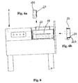
- the cutting frame 22 shown in Figure 6b is aligned in front of the outlet cross section of the insertion shaft 2, the attachment of the Cutting frame 22 is carried out with the same fastening elements 23 with which in the cube cutting operation the gate frames are attached.
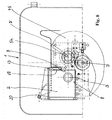
- a cutting knife is used in the disc cutting operation 7S used, which is attached to the gate shaft 6h and thus rotates about the axis of rotation D '.
- the axis of rotation of the 7S cutting knife is thus compared to the cube cutting operation offset upwards, which prevents the material to be cut obliquely to the top left of Floor plate 8 of the insertion slot 2 can be lifted off.
- the cutting frame 22 has such a depth that the cutting knife 7S with a very small distance on the end face 22S of the cutting frame 22 sweeps past, so that the front edge 24 as a shear bar works and ensures a good cutting result.
- the conversion of the machine 1 from one to the other mode of operation takes only a few Minutes. Due to the tool-free disassembly of the longitudinal walls The machine 1 can form components forming 10S and 10G in the area of the insertion shaft 2 very easy to clean so that even the highest hygiene requirements are met can.
Landscapes
- Life Sciences & Earth Sciences (AREA)
- Forests & Forestry (AREA)
- Engineering & Computer Science (AREA)
- Mechanical Engineering (AREA)
- Food-Manufacturing Devices (AREA)
- Details Of Cutting Devices (AREA)
- Formation And Processing Of Food Products (AREA)
- Preparation Of Fruits And Vegetables (AREA)
- Crushing And Pulverization Processes (AREA)
- Sawing (AREA)
Abstract
Description
- Figur 1
- eine Vorderansicht einer Maschine im Würfelschneidbetrieb
- Figur 1a
- eine Vorderansicht eines Reduzierteils
- Figur 1b
- eine Vorderansicht eines Trennschiebers
- Figur 2
- eine Seitenansicht der Maschine gemäß Figur 1
- Figur 2a
- eine Seitenansicht einer Vorschubplatte
- Figur 2b
- eine Seitenansicht eines Schneidgatters
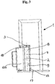
- Figur 3
- eine Draufsicht auf die Maschine gemäß Figur 1
- Figur 4
- einen vergrößerten Ausschnitt der Vorderansicht gemäß Figur 1
- Figur 5
- wie Figur 1, jedoch im Scheibenschneidbetrieb
- Figur 5a
- eine Vorderansicht einer Längswand
- Figur 5b
- eine Vorderansicht eines Abdeckelements
- Figur 5c
- eine Vorderansicht eines Beschickungsdeckels
- Figur 6
- wie Figur 2, jedoch im Scheibenschneidbetrieb
- Figur 6a
- wie Figur 2a, jedoch im Scheibenschneidbetrieb
- Figur 6b
- einen Längsschnitt durch einen Schneidrahmen
- Figur 7
- wie Figur 3, jedoch im Scheibenschneidbetrieb
- Figur 8
- wie Figur 4, jedoch im Scheibenschneidbetrieb
Claims (15)
- Maschine (1) zum Schneiden von Lebensmitteln in Scheiben, Streifen oder Würfel mit einem Einlegeschacht (2) für das Schneidgut, das darin mittels einer Vorschubeinrichtung in Richtung auf eine sich über einen Austrittsquerschnitt des Einlegeschachts (2) erstreckende Schneideinrichtung vorschiebbar ist, die Gattermesser und ein rotierendes Abschneidemesser (7G, 7S) aufweist, wobei der Innenquerschnitt des Einlegeschachts (2) durch Veränderung der Position mindestens einer seiner Längswände (10G, 10S) veränderbar ist, dadurch gekennzeichnet, daß der Austrittsquerschnitts des Einlegeschachts (2) über einen im Gatterschneidbetrieb wirksamen Schneidquerschnitt hinaus vergrößerbar ist.
- Maschine nach Anspruch 1, dadurch gekennzeichnet, daß der Austrittsquerschnitt und der Innenquerschnitt in gleichem Maße vergrößerbar sind.
- Maschine nach Anspruch 1 oder 2, dadurch gekennzeichnet, daß eine Längswand (10G, 10S) des Einlegeschachts (2) von der Maschine (1) entfernbar und in eine andere Längswand (10S, 10G) in einer anderen Position mit der Maschine (1) verbindbar ist.
- Maschine nach einem der Ansprüche 1 bis 3, dadurch gekennzeichnet, daß ein L-förmiges Reduzierteil (16) aus einer Vorderwand (17) der Maschine (1) entfernbar ist, wobei die L-Schenkel mit ihren Innenkanten einen kleinen Austrittsquerschnitt des Einlegeschachts (2) und mit ihren Außenkanten einen großen Austrittsquerschnitt definieren.
- Maschine nach Anspruch 4, dadurch gekennzeichnet, daß das Reduzierteil (16) und eine Längswand (1OG) des Einlegeschachts (2) eine Baueinheit bilden.
- Maschine nach einem der Ansprüche 1 bis 5, dadurch gekennzeichnet, daß eine Längswand (10S, 10G) mit mindestens einer stirnseitigen Nut versehen ist, in die ein mit einem Maschinengehäuse verbundener Steg eingreift.
- Maschine nach einem der Ansprüche 1 bis 6, dadurch gekennzeichnet, daß eine Längswand (10G) einen in Längsrichtung verlaufenden Schlitz (14) zur Einführung eines Trennschiebers (12G) aufweist, der mit einer Gegenschneide in Form eines Rücksprungs (13) in einer gegenüberliegenden Längswand zusammenwirkt.
- Maschine nach Anspruch 7, dadurch gekennzeichnet, daß ein Bereich oberhalb des Rücksprungs (13) derart mit einem Abdeckelement (19) ausfüllbar ist, daß sich die Oberfläche der hierdurch gebildeten Längswand in einer einzigen Ebene erstreckt.
- Maschine nach Anspruch 8, dadurch gekennzeichnet, daß eine Oberseite des Abdeckelements (19) eine Führungsfläche für einen horizontal verschiebbaren Beschickungsdeckel (20) bildet.
- Maschine (1) zum Schneiden von Lebensmitteln in Scheiben, Streifen oder Würfel mit einem Einlegeschacht (2) für das Schneidgut, das darin mittels einer Vorschubeinrichtung in Richtung auf eine sich über einen Austrittsquerschnitt des Einlegeschachts (2) erstreckende Schneideinrichtung vorschiebbar ist, die Gattermesser und ein rotierendes Abschneidemesser (7G, 7S) aufweist, dadurch gekennzeichnet, daß das Abschneidemesser (7G, 7S) um wenigstens eine weitere Drehachse (D') rotierbar ist, die parallel zu der im Gatterschneidbetrieb wirksamen Drehachse (D) verläuft und im Abstand zu dieser angeordnet ist.
- Maschine nach Anspruch 10, dadurch gekennzeichnet, daß die weitere Drehachse (D') oberhalb einer durch das Bodenblech (8) des Einlegeschachts (2) definierten Ebene verläuft.
- Maschine nach Anspruch 10 oder 11, dadurch gekennzeichnet, daß das Abschneidemesser (7S) auf der Antriebswelle (6h) eines Messergatters (5h) befestigbar ist.
- Maschine nach einem der Ansprüche 10 bis 12, dadurch gekennzeichnet, daß die Antriebswelle (6h) eines Messergatters (5h), auf der das Abschneidemesser (7S) befestigbar ist, die Hauptantriebswelle der Maschine (1) ist, von der die Antriebswellen (25, 6V) des Abschneidemessers (7G) im Würfelschneidbetrieb und des anderen Messergatters (5v) antreibbar sind.
- Maschine nach einem der Ansprüche 1 bis 13, dadurch gekennzeichnet, daß an der Vorderwand (17) der Maschine (1) ein Schneidrahmen (22) befestigbar ist, dessen Durchtrittsöffnung einen Querschnitt aufweist, der mit einem vergrößerten Austrittsquerschnitt des Einlegeschachts (2) fluchtet und dessen der Vorderwand (17) abgewandte Stirnfläche (23) unmittelbar angrenzend an die Schneidebene des Abschneidemessers (7S) verläuft.
- Maschine nach einem der Ansprüche 1 bis 14, dadurch gekennzeichnet, daß eine Messerkastentür mit einem Entnahmeschacht versehen ist, dessen Eintrittsquerschnitt mit dem Austrittsquerschnitt des Schneidrahmens fluchtet.
Applications Claiming Priority (2)
| Application Number | Priority Date | Filing Date | Title |
|---|---|---|---|
| DE19957840A DE19957840A1 (de) | 1999-12-01 | 1999-12-01 | Maschine zum Schneiden von Lebensmitteln |
| DE19957840 | 1999-12-01 |
Publications (3)
| Publication Number | Publication Date |
|---|---|
| EP1106312A2 true EP1106312A2 (de) | 2001-06-13 |
| EP1106312A3 EP1106312A3 (de) | 2004-03-03 |
| EP1106312B1 EP1106312B1 (de) | 2006-02-01 |
Family
ID=7931007
Family Applications (1)
| Application Number | Title | Priority Date | Filing Date |
|---|---|---|---|
| EP00124025A Expired - Lifetime EP1106312B1 (de) | 1999-12-01 | 2000-11-04 | Maschine zum Schneiden von Lebensmitteln |
Country Status (5)
| Country | Link |
|---|---|
| EP (1) | EP1106312B1 (de) |
| AT (1) | ATE316848T1 (de) |
| DE (2) | DE19957840A1 (de) |
| DK (1) | DK1106312T3 (de) |
| ES (1) | ES2255936T3 (de) |
Cited By (1)
| Publication number | Priority date | Publication date | Assignee | Title |
|---|---|---|---|---|
| CN108162019A (zh) * | 2017-12-26 | 2018-06-15 | 阜阳市卓创科技服务生产力促进中心 | 一种水产加工用的切块机 |
Family Cites Families (4)
| Publication number | Priority date | Publication date | Assignee | Title |
|---|---|---|---|---|
| DD218028A1 (de) * | 1983-10-21 | 1985-01-30 | Nahrungsguetermaschinenbau Veb | Vorrichtung zum schneiden von lebensmitteln, insbesondere in streifen, wuerfeln oder dgl. |
| DE3403218C2 (de) * | 1984-01-31 | 1995-07-20 | Holac Maschbau Gmbh | Verfahren zum Schneiden von Lebensmitteln in Streifen- oder Würfelform und Schneidmaschine hierfür |
| DE3540904C2 (de) * | 1985-11-19 | 1995-08-10 | Holac Maschbau Gmbh | Vorrichtung zum Schneiden von Lebensmitteln, insbesondere von Fleisch |
| DE4444506C1 (de) * | 1994-12-14 | 1996-09-05 | Uwe Reifenhaeuser | Schneidvorrichtung |
-
1999
- 1999-12-01 DE DE19957840A patent/DE19957840A1/de not_active Withdrawn
-
2000
- 2000-11-04 DE DE50012158T patent/DE50012158D1/de not_active Expired - Lifetime
- 2000-11-04 EP EP00124025A patent/EP1106312B1/de not_active Expired - Lifetime
- 2000-11-04 DK DK00124025T patent/DK1106312T3/da active
- 2000-11-04 AT AT00124025T patent/ATE316848T1/de active
- 2000-11-04 ES ES00124025T patent/ES2255936T3/es not_active Expired - Lifetime
Cited By (1)
| Publication number | Priority date | Publication date | Assignee | Title |
|---|---|---|---|---|
| CN108162019A (zh) * | 2017-12-26 | 2018-06-15 | 阜阳市卓创科技服务生产力促进中心 | 一种水产加工用的切块机 |
Also Published As
| Publication number | Publication date |
|---|---|
| DK1106312T3 (da) | 2006-06-06 |
| DE19957840A1 (de) | 2001-06-21 |
| ATE316848T1 (de) | 2006-02-15 |
| EP1106312B1 (de) | 2006-02-01 |
| EP1106312A3 (de) | 2004-03-03 |
| ES2255936T3 (es) | 2006-07-16 |
| DE50012158D1 (de) | 2006-04-13 |
Similar Documents
| Publication | Publication Date | Title |
|---|---|---|
| EP3102376B1 (de) | Schneideverfahren und schneidmaschine für strangförmige lebensmittel | |
| EP2045053A2 (de) | Scheibenschneidmaschine für strangförmige Lebensmittel | |
| DE69306912T2 (de) | Verfahren und Vorrichtung zur Verbesserung der Leistung beim ununterbrochenen Schneidvorgang von Lebensmitteln | |
| DE9308956U1 (de) | Schneidegerät | |
| EP2370235B1 (de) | Küchenhobel | |
| CH659405A5 (de) | Zerkleinerungsvorrichtung fuer abfall. | |
| WO2013110689A1 (de) | Vorrichtung zum schneiden und verpacken von brot | |
| EP1938932B1 (de) | Maschine zum Schneiden von strangförmigen Lebensmitteln in Scheiben sowie Schneidverfahren | |
| EP1106312B1 (de) | Maschine zum Schneiden von Lebensmitteln | |
| EP2080599A1 (de) | Maschine zum Schneiden von Lebensmitteln in Streifen oder Würfel | |
| DE102007021370B3 (de) | Verfahren und Vorrichtung zum Schneiden von Lebensmitteln in Streifen, Scheiben oder Würfel | |
| DE19634298C2 (de) | Vorrichtung zum Würfelschneiden von Fleisch, Wurstwaren und dergleichen Lebensmitteln | |
| DE102018108300A1 (de) | Lageranordnung sowie damit ausgestattete Bearbeitungs-Vorrichtung | |
| EP2138286B1 (de) | Maschine zum Schneiden von Lebensmitteln | |
| EP0068305A1 (de) | Gerät zum Entnehmen von Futterportionen aus Flach- oder Fahrsilos | |
| EP3599067A1 (de) | Schneidmaschine für strangförmige lebensmittel | |
| DE102006025615B3 (de) | Abstreifvorrichtung für eine Lebensmittel-Streifenschneidemaschine, Lebensmittel-Streifenschneidemaschine und Verfahren zur Herstellung einer Abstreifvorrichtung | |
| EP0222068B1 (de) | Küchengerät zum Schneiden von Gemüse, insbesondere Kartoffeln in Streifen | |
| EP1136200B1 (de) | Maschine zum Schneiden von Lebensmitteln in Streifen oder Würfel | |
| DE19917390A1 (de) | Vorrichtung zum Bearbeiten eines Teigstrangs | |
| DE19738268C1 (de) | Lebensmittelschneidemaschine | |
| DE10331320A1 (de) | Rotationsschneidmesser | |
| EP1055492A2 (de) | Maschine zum Schneiden von Lebensmitteln, insbesondere von Gemüse, in Streifen | |
| EP4389372A1 (de) | Schneidmaschine für strangförmige lebensmittel | |
| DE9311101U1 (de) | Schneidmaschine für Fleisch- und Wurstwaren |
Legal Events
| Date | Code | Title | Description |
|---|---|---|---|
| PUAI | Public reference made under article 153(3) epc to a published international application that has entered the european phase |
Free format text: ORIGINAL CODE: 0009012 |
|
| AK | Designated contracting states |
Kind code of ref document: A2 Designated state(s): AT BE CH CY DE DK ES FI FR GB GR IE IT LI LU MC NL PT SE TR |
|
| AX | Request for extension of the european patent |
Free format text: AL;LT;LV;MK;RO;SI |
|
| RIC1 | Information provided on ipc code assigned before grant |
Ipc: 7B 26D 3/18 B Ipc: 7B 26D 1/28 B Ipc: 7B 26D 7/06 A Ipc: 7B 26D 1/16 B Ipc: 7B 26D 7/01 B |
|
| PUAL | Search report despatched |
Free format text: ORIGINAL CODE: 0009013 |
|
| AK | Designated contracting states |
Kind code of ref document: A3 Designated state(s): AT BE CH CY DE DK ES FI FR GB GR IE IT LI LU MC NL PT SE TR |
|
| AX | Request for extension of the european patent |
Extension state: AL LT LV MK RO SI |
|
| 17P | Request for examination filed |
Effective date: 20040728 |
|
| AKX | Designation fees paid |
Designated state(s): AT BE CH CY DE DK ES FI FR GB GR IE IT LI LU MC NL PT SE TR |
|
| 17Q | First examination report despatched |
Effective date: 20050128 |
|
| GRAP | Despatch of communication of intention to grant a patent |
Free format text: ORIGINAL CODE: EPIDOSNIGR1 |
|
| GRAS | Grant fee paid |
Free format text: ORIGINAL CODE: EPIDOSNIGR3 |
|
| GRAA | (expected) grant |
Free format text: ORIGINAL CODE: 0009210 |
|
| AK | Designated contracting states |
Kind code of ref document: B1 Designated state(s): AT BE CH CY DE DK ES FI FR GB GR IE IT LI LU MC NL PT SE TR |
|
| PG25 | Lapsed in a contracting state [announced via postgrant information from national office to epo] |
Ref country code: IT Free format text: LAPSE BECAUSE OF FAILURE TO SUBMIT A TRANSLATION OF THE DESCRIPTION OR TO PAY THE FEE WITHIN THE PRESCRIBED TIME-LIMIT;WARNING: LAPSES OF ITALIAN PATENTS WITH EFFECTIVE DATE BEFORE 2007 MAY HAVE OCCURRED AT ANY TIME BEFORE 2007. THE CORRECT EFFECTIVE DATE MAY BE DIFFERENT FROM THE ONE RECORDED. Effective date: 20060201 Ref country code: IE Free format text: LAPSE BECAUSE OF FAILURE TO SUBMIT A TRANSLATION OF THE DESCRIPTION OR TO PAY THE FEE WITHIN THE PRESCRIBED TIME-LIMIT Effective date: 20060201 Ref country code: FI Free format text: LAPSE BECAUSE OF FAILURE TO SUBMIT A TRANSLATION OF THE DESCRIPTION OR TO PAY THE FEE WITHIN THE PRESCRIBED TIME-LIMIT Effective date: 20060201 |
|
| REG | Reference to a national code |
Ref country code: GB Ref legal event code: FG4D Free format text: NOT ENGLISH |
|
| REG | Reference to a national code |
Ref country code: CH Ref legal event code: EP |
|
| REG | Reference to a national code |
Ref country code: IE Ref legal event code: FG4D Free format text: LANGUAGE OF EP DOCUMENT: GERMAN |
|
| REG | Reference to a national code |
Ref country code: SE Ref legal event code: TRGR |
|
| GBT | Gb: translation of ep patent filed (gb section 77(6)(a)/1977) |
Effective date: 20060322 |
|
| REF | Corresponds to: |
Ref document number: 50012158 Country of ref document: DE Date of ref document: 20060413 Kind code of ref document: P |
|
| REG | Reference to a national code |
Ref country code: CH Ref legal event code: NV Representative=s name: PA ALDO ROEMPLER |
|
| REG | Reference to a national code |
Ref country code: DK Ref legal event code: T3 |
|
| PG25 | Lapsed in a contracting state [announced via postgrant information from national office to epo] |
Ref country code: PT Free format text: LAPSE BECAUSE OF FAILURE TO SUBMIT A TRANSLATION OF THE DESCRIPTION OR TO PAY THE FEE WITHIN THE PRESCRIBED TIME-LIMIT Effective date: 20060703 |
|
| REG | Reference to a national code |
Ref country code: ES Ref legal event code: FG2A Ref document number: 2255936 Country of ref document: ES Kind code of ref document: T3 |
|
| REG | Reference to a national code |
Ref country code: IE Ref legal event code: FD4D |
|
| ET | Fr: translation filed | ||
| PG25 | Lapsed in a contracting state [announced via postgrant information from national office to epo] |
Ref country code: MC Free format text: LAPSE BECAUSE OF NON-PAYMENT OF DUE FEES Effective date: 20061130 |
|
| PLBE | No opposition filed within time limit |
Free format text: ORIGINAL CODE: 0009261 |
|
| STAA | Information on the status of an ep patent application or granted ep patent |
Free format text: STATUS: NO OPPOSITION FILED WITHIN TIME LIMIT |
|
| 26N | No opposition filed |
Effective date: 20061103 |
|
| PG25 | Lapsed in a contracting state [announced via postgrant information from national office to epo] |
Ref country code: GR Free format text: LAPSE BECAUSE OF FAILURE TO SUBMIT A TRANSLATION OF THE DESCRIPTION OR TO PAY THE FEE WITHIN THE PRESCRIBED TIME-LIMIT Effective date: 20060502 |
|
| PG25 | Lapsed in a contracting state [announced via postgrant information from national office to epo] |
Ref country code: LU Free format text: LAPSE BECAUSE OF NON-PAYMENT OF DUE FEES Effective date: 20061104 Ref country code: TR Free format text: LAPSE BECAUSE OF FAILURE TO SUBMIT A TRANSLATION OF THE DESCRIPTION OR TO PAY THE FEE WITHIN THE PRESCRIBED TIME-LIMIT Effective date: 20060201 |
|
| REG | Reference to a national code |
Ref country code: CH Ref legal event code: PCAR Free format text: ALDO ROEMPLER PATENTANWALT;BRENDENWEG 11 POSTFACH 154;9424 RHEINECK (CH) |
|
| PG25 | Lapsed in a contracting state [announced via postgrant information from national office to epo] |
Ref country code: CY Free format text: LAPSE BECAUSE OF FAILURE TO SUBMIT A TRANSLATION OF THE DESCRIPTION OR TO PAY THE FEE WITHIN THE PRESCRIBED TIME-LIMIT Effective date: 20060201 |
|
| PGFP | Annual fee paid to national office [announced via postgrant information from national office to epo] |
Ref country code: DK Payment date: 20141126 Year of fee payment: 15 |
|
| PGFP | Annual fee paid to national office [announced via postgrant information from national office to epo] |
Ref country code: ES Payment date: 20141222 Year of fee payment: 15 Ref country code: CH Payment date: 20141126 Year of fee payment: 15 Ref country code: SE Payment date: 20141126 Year of fee payment: 15 Ref country code: GB Payment date: 20141128 Year of fee payment: 15 |
|
| PGFP | Annual fee paid to national office [announced via postgrant information from national office to epo] |
Ref country code: NL Payment date: 20141125 Year of fee payment: 15 |
|
| PGFP | Annual fee paid to national office [announced via postgrant information from national office to epo] |
Ref country code: IT Payment date: 20141120 Year of fee payment: 15 |
|
| REG | Reference to a national code |
Ref country code: FR Ref legal event code: PLFP Year of fee payment: 16 |
|
| REG | Reference to a national code |
Ref country code: DK Ref legal event code: EBP Effective date: 20151130 |
|
| REG | Reference to a national code |
Ref country code: CH Ref legal event code: PL |
|
| GBPC | Gb: european patent ceased through non-payment of renewal fee |
Effective date: 20151104 |
|
| PG25 | Lapsed in a contracting state [announced via postgrant information from national office to epo] |
Ref country code: IT Free format text: LAPSE BECAUSE OF NON-PAYMENT OF DUE FEES Effective date: 20151104 Ref country code: LI Free format text: LAPSE BECAUSE OF NON-PAYMENT OF DUE FEES Effective date: 20151130 Ref country code: CH Free format text: LAPSE BECAUSE OF NON-PAYMENT OF DUE FEES Effective date: 20151130 |
|
| REG | Reference to a national code |
Ref country code: NL Ref legal event code: MM Effective date: 20151201 |
|
| PG25 | Lapsed in a contracting state [announced via postgrant information from national office to epo] |
Ref country code: SE Free format text: LAPSE BECAUSE OF NON-PAYMENT OF DUE FEES Effective date: 20151105 |
|
| PG25 | Lapsed in a contracting state [announced via postgrant information from national office to epo] |
Ref country code: NL Free format text: LAPSE BECAUSE OF NON-PAYMENT OF DUE FEES Effective date: 20151201 |
|
| PG25 | Lapsed in a contracting state [announced via postgrant information from national office to epo] |
Ref country code: GB Free format text: LAPSE BECAUSE OF NON-PAYMENT OF DUE FEES Effective date: 20151104 Ref country code: DK Free format text: LAPSE BECAUSE OF NON-PAYMENT OF DUE FEES Effective date: 20151130 |
|
| REG | Reference to a national code |
Ref country code: FR Ref legal event code: PLFP Year of fee payment: 17 |
|
| REG | Reference to a national code |
Ref country code: ES Ref legal event code: FD2A Effective date: 20161229 |
|
| PG25 | Lapsed in a contracting state [announced via postgrant information from national office to epo] |
Ref country code: ES Free format text: LAPSE BECAUSE OF NON-PAYMENT OF DUE FEES Effective date: 20151105 |
|
| REG | Reference to a national code |
Ref country code: FR Ref legal event code: PLFP Year of fee payment: 18 |
|
| PGFP | Annual fee paid to national office [announced via postgrant information from national office to epo] |
Ref country code: FR Payment date: 20171127 Year of fee payment: 18 Ref country code: DE Payment date: 20171130 Year of fee payment: 18 |
|
| PGFP | Annual fee paid to national office [announced via postgrant information from national office to epo] |
Ref country code: BE Payment date: 20171124 Year of fee payment: 18 Ref country code: AT Payment date: 20171128 Year of fee payment: 18 |
|
| REG | Reference to a national code |
Ref country code: DE Ref legal event code: R119 Ref document number: 50012158 Country of ref document: DE |
|
| REG | Reference to a national code |
Ref country code: AT Ref legal event code: MM01 Ref document number: 316848 Country of ref document: AT Kind code of ref document: T Effective date: 20181104 |
|
| REG | Reference to a national code |
Ref country code: BE Ref legal event code: MM Effective date: 20181130 |
|
| PG25 | Lapsed in a contracting state [announced via postgrant information from national office to epo] |
Ref country code: AT Free format text: LAPSE BECAUSE OF NON-PAYMENT OF DUE FEES Effective date: 20181104 Ref country code: DE Free format text: LAPSE BECAUSE OF NON-PAYMENT OF DUE FEES Effective date: 20190601 Ref country code: FR Free format text: LAPSE BECAUSE OF NON-PAYMENT OF DUE FEES Effective date: 20181130 |
|
| PG25 | Lapsed in a contracting state [announced via postgrant information from national office to epo] |
Ref country code: BE Free format text: LAPSE BECAUSE OF NON-PAYMENT OF DUE FEES Effective date: 20181130 |