EP1106401B1 - Procédé pour la commande ou la régulation du niveau de la carosserie d'un véhicule automobile - Google Patents
Procédé pour la commande ou la régulation du niveau de la carosserie d'un véhicule automobile Download PDFInfo
- Publication number
- EP1106401B1 EP1106401B1 EP00125451A EP00125451A EP1106401B1 EP 1106401 B1 EP1106401 B1 EP 1106401B1 EP 00125451 A EP00125451 A EP 00125451A EP 00125451 A EP00125451 A EP 00125451A EP 1106401 B1 EP1106401 B1 EP 1106401B1
- Authority
- EP
- European Patent Office
- Prior art keywords
- level
- vehicle body
- control unit
- lowering process
- air
- Prior art date
- Legal status (The legal status is an assumption and is not a legal conclusion. Google has not performed a legal analysis and makes no representation as to the accuracy of the status listed.)
- Expired - Lifetime
Links
- 238000000034 method Methods 0.000 title claims description 110
- 230000001276 controlling effect Effects 0.000 title description 3
- 230000001105 regulatory effect Effects 0.000 title description 2
- 230000008569 process Effects 0.000 claims description 79
- 230000000977 initiatory effect Effects 0.000 claims description 16
- 206010000210 abortion Diseases 0.000 claims description 11
- 230000008859 change Effects 0.000 claims description 6
- 238000007599 discharging Methods 0.000 claims description 6
- 230000008901 benefit Effects 0.000 description 17
- 238000011161 development Methods 0.000 description 17
- 230000000740 bleeding effect Effects 0.000 description 8
- 230000005283 ground state Effects 0.000 description 4
- 238000010926 purge Methods 0.000 description 4
- 230000007423 decrease Effects 0.000 description 3
- 238000013022 venting Methods 0.000 description 3
- 239000003795 chemical substances by application Substances 0.000 description 2
- 238000010586 diagram Methods 0.000 description 2
- 238000005259 measurement Methods 0.000 description 2
- 230000009467 reduction Effects 0.000 description 2
- 238000012935 Averaging Methods 0.000 description 1
- 238000010276 construction Methods 0.000 description 1
- 238000012937 correction Methods 0.000 description 1
- 238000013461 design Methods 0.000 description 1
- 239000012530 fluid Substances 0.000 description 1
- 238000004519 manufacturing process Methods 0.000 description 1
- 238000003825 pressing Methods 0.000 description 1
- 230000000717 retained effect Effects 0.000 description 1
- 230000003068 static effect Effects 0.000 description 1
- 230000007704 transition Effects 0.000 description 1
Images


Classifications
-
- B—PERFORMING OPERATIONS; TRANSPORTING
- B60—VEHICLES IN GENERAL
- B60G—VEHICLE SUSPENSION ARRANGEMENTS
- B60G17/00—Resilient suspensions having means for adjusting the spring or vibration-damper characteristics, for regulating the distance between a supporting surface and a sprung part of vehicle or for locking suspension during use to meet varying vehicular or surface conditions, e.g. due to speed or load
- B60G17/015—Resilient suspensions having means for adjusting the spring or vibration-damper characteristics, for regulating the distance between a supporting surface and a sprung part of vehicle or for locking suspension during use to meet varying vehicular or surface conditions, e.g. due to speed or load the regulating means comprising electric or electronic elements
- B60G17/0152—Resilient suspensions having means for adjusting the spring or vibration-damper characteristics, for regulating the distance between a supporting surface and a sprung part of vehicle or for locking suspension during use to meet varying vehicular or surface conditions, e.g. due to speed or load the regulating means comprising electric or electronic elements characterised by the action on a particular type of suspension unit
- B60G17/0155—Resilient suspensions having means for adjusting the spring or vibration-damper characteristics, for regulating the distance between a supporting surface and a sprung part of vehicle or for locking suspension during use to meet varying vehicular or surface conditions, e.g. due to speed or load the regulating means comprising electric or electronic elements characterised by the action on a particular type of suspension unit pneumatic unit
-
- B—PERFORMING OPERATIONS; TRANSPORTING
- B60—VEHICLES IN GENERAL
- B60G—VEHICLE SUSPENSION ARRANGEMENTS
- B60G17/00—Resilient suspensions having means for adjusting the spring or vibration-damper characteristics, for regulating the distance between a supporting surface and a sprung part of vehicle or for locking suspension during use to meet varying vehicular or surface conditions, e.g. due to speed or load
- B60G17/02—Spring characteristics, e.g. mechanical springs and mechanical adjusting means
- B60G17/04—Spring characteristics, e.g. mechanical springs and mechanical adjusting means fluid spring characteristics
- B60G17/052—Pneumatic spring characteristics
- B60G17/0523—Regulating distributors or valves for pneumatic springs
-
- B—PERFORMING OPERATIONS; TRANSPORTING
- B60—VEHICLES IN GENERAL
- B60G—VEHICLE SUSPENSION ARRANGEMENTS
- B60G2202/00—Indexing codes relating to the type of spring, damper or actuator
- B60G2202/40—Type of actuator
- B60G2202/41—Fluid actuator
- B60G2202/412—Pneumatic actuator
-
- B—PERFORMING OPERATIONS; TRANSPORTING
- B60—VEHICLES IN GENERAL
- B60G—VEHICLE SUSPENSION ARRANGEMENTS
- B60G2400/00—Indexing codes relating to detected, measured or calculated conditions or factors
- B60G2400/25—Stroke; Height; Displacement
- B60G2400/252—Stroke; Height; Displacement vertical
-
- B—PERFORMING OPERATIONS; TRANSPORTING
- B60—VEHICLES IN GENERAL
- B60G—VEHICLE SUSPENSION ARRANGEMENTS
- B60G2500/00—Indexing codes relating to the regulated action or device
- B60G2500/20—Spring action or springs
- B60G2500/201—Air spring system type
- B60G2500/2012—Open systems
-
- B—PERFORMING OPERATIONS; TRANSPORTING
- B60—VEHICLES IN GENERAL
- B60G—VEHICLE SUSPENSION ARRANGEMENTS
- B60G2500/00—Indexing codes relating to the regulated action or device
- B60G2500/20—Spring action or springs
- B60G2500/204—Pressure regulating valves for air-springs
- B60G2500/2042—Air filling valves
-
- B—PERFORMING OPERATIONS; TRANSPORTING
- B60—VEHICLES IN GENERAL
- B60G—VEHICLE SUSPENSION ARRANGEMENTS
- B60G2500/00—Indexing codes relating to the regulated action or device
- B60G2500/20—Spring action or springs
- B60G2500/204—Pressure regulating valves for air-springs
- B60G2500/2044—Air exhausting valves
-
- B—PERFORMING OPERATIONS; TRANSPORTING
- B60—VEHICLES IN GENERAL
- B60G—VEHICLE SUSPENSION ARRANGEMENTS
- B60G2500/00—Indexing codes relating to the regulated action or device
- B60G2500/20—Spring action or springs
- B60G2500/205—Air-compressor operation
-
- B—PERFORMING OPERATIONS; TRANSPORTING
- B60—VEHICLES IN GENERAL
- B60G—VEHICLE SUSPENSION ARRANGEMENTS
- B60G2500/00—Indexing codes relating to the regulated action or device
- B60G2500/30—Height or ground clearance
-
- B—PERFORMING OPERATIONS; TRANSPORTING
- B60—VEHICLES IN GENERAL
- B60G—VEHICLE SUSPENSION ARRANGEMENTS
- B60G2800/00—Indexing codes relating to the type of movement or to the condition of the vehicle and to the end result to be achieved by the control action
- B60G2800/90—System Controller type
- B60G2800/91—Suspension Control
- B60G2800/912—Attitude Control; levelling control
-
- B—PERFORMING OPERATIONS; TRANSPORTING
- B60—VEHICLES IN GENERAL
- B60G—VEHICLE SUSPENSION ARRANGEMENTS
- B60G2800/00—Indexing codes relating to the type of movement or to the condition of the vehicle and to the end result to be achieved by the control action
- B60G2800/90—System Controller type
- B60G2800/91—Suspension Control
- B60G2800/914—Height Control System
-
- Y—GENERAL TAGGING OF NEW TECHNOLOGICAL DEVELOPMENTS; GENERAL TAGGING OF CROSS-SECTIONAL TECHNOLOGIES SPANNING OVER SEVERAL SECTIONS OF THE IPC; TECHNICAL SUBJECTS COVERED BY FORMER USPC CROSS-REFERENCE ART COLLECTIONS [XRACs] AND DIGESTS
- Y10—TECHNICAL SUBJECTS COVERED BY FORMER USPC
- Y10S—TECHNICAL SUBJECTS COVERED BY FORMER USPC CROSS-REFERENCE ART COLLECTIONS [XRACs] AND DIGESTS
- Y10S280/00—Land vehicles
- Y10S280/01—Load responsive, leveling of vehicle
Definitions
- Modern motor vehicles often have a level control system, e.g. in the form of an air spring system, which has air springs as actuators.
- a predetermined level is stored, which is to take the vehicle body of the motor vehicle relative to a fixed reference point.
- the predetermined level can optionally be adapted by the driver of the motor vehicle to the current driving situation. If, for example, a particularly large ground clearance of the motor vehicle is necessary in the field, the driver, e.g. via a switch in the dashboard, in the control unit specify a correspondingly high level.
- Level control systems have the advantage that the predetermined level regardless of the load condition of the motor vehicle by lowering or Lifting the vehicle body can be maintained.
- the vehicle body can be lowered to a low level, for example, to allow easy loading of the vehicle.
- the vehicle body of the motor vehicle may sit on the ground (e.g., on snow or off-road) with the wheels of the motor vehicle falling against the vehicle body.
- the current level of the vehicle body may be higher than the level preset in the control unit, such that the control unit initiates a bleed operation of the vehicle (e.g., by venting compressed air from the air springs of an air spring system) to adjust the current level to the predetermined level.
- the motor vehicle If the motor vehicle is taken down from the lift, it drops below the predetermined level due to the small level of control in the actuators, so that the actuators must be refilled with the actuator to raise the vehicle body to the predetermined level. This is time consuming and stressed In addition, the components of the level control system with which the actuating agent is fed into the actuators.
- the invention has for its object to provide a method for controlling or regulating the level of a vehicle body of a motor vehicle by means of a level control system with annensitzen the vehicle body on the ground or on a lift can be detected as early as possible to an unwanted lowering of Vehicle levels as far as possible to avoid.
- a discharge operation is understood to mean a process by which the current level of the vehicle body is to be adjusted by discharging actuating means from the actuators of the level control system to the level specified in the control unit until this is reached. Accordingly, the termination of a bleed operation is understood to mean that further bleeding of actuation means from the actuators of the self-leveling system is inhibited even though the current level of the vehicle body is above the level preset in the control unit.
- the current level of the vehicle body is preferably determined by means of one or more height sensors.
- the basic idea of the invention is to be seen in that after initiation of a discharge process by the control unit is checked after a short period of time whether the vehicle body has lowered according to a specification from the determined level and the control unit aborts the discharge process, if this is not the case is.
- the control unit can decide whether the vehicle body is seated on the ground or on a lift.
- the vehicle is on a lift and it is taken down from this, it does not decrease or only insignificantly from the level that it has had before lifting by the lift off, so that no or only a slight correction of the level of Vehicle construction is required.
- a long lifting operation is thus eliminated (in contrast, the actuators are largely emptied in conventional level control systems, so that a long lifting operation of the vehicle body is necessary when the motor vehicle is removed from the lift).
- the control unit aborts the discharge process even if the vehicle body has lowered after initiation of the discharge process according to a specification, but reduced after initiation of the discharge process the Stellstoffbuch für or at least one Radaufstandskraft beyond a predetermined amount Has. Based on the reduction of the Stellstofftechnikes or Radaufstandskraft the control unit determines that the vehicle during the discharge z. B. has placed on the ground-hat.
- the advantage of the development is the fact that in this case the discharge process is canceled, so that an increased seating of the vehicle is suppressed on the ground.
- the advantage of the development according to claim 3 is the fact that even after a short period of time (typically, the time intervals have a length of 1 to 5 seconds) can be determined whether the vehicle body has ever lowered during a time interval or possibly even is raised. With the help of this development can be quickly determined during a discharge process that the vehicle is raised with a jack or a lift. Through the development of the advantage that a maximum possible amount of the actuating means remains in the actuators of the level control system.
- the advantage of the development according to claim 4 is understandable, if one considers the following: In a level control system in which the level of the vehicle body is lowered by discharging an actuator of actuators, in the maximum level of the vehicle body, the relationship between the amount of the actuator in the actuators and the level of the vehicle body is not unique. For example, the case may occur that a loaded vehicle is unloaded and springs by the discharge in a built-stop and so merges into the maximum level. If, in this case, adjusting means are discharged from the actuators, then the level of the vehicle body does not drop immediately after the initiation of the discharge process from the maximum level.
- the vehicle body drops only after a certain period of time, when so much actuating means has been discharged from the actuators, that at the low vehicle weight of the vehicle body drops from the maximum level.
- this problem does not exist so that the vehicle body lowers immediately after initiation of the bleed operation (unless the vehicle is unloaded or lifted during the bleed operation).
- the maximum possible amount of the actuating means in the actuators of the level control system remains present in all possible levels of the vehicle body.
- the development according to claim 5 is preferably used when the current level determined before the discharge process is below the maximum level. In this case, the vehicle body lowers in each time interval with constant Radaufstands adoptedn already by a predetermined level, unless the motor vehicle is in a critical situation or is unloaded.
- the advantage of this development is the fact that in the control unit a critical situation of a discharge of the motor vehicle during a discharge process can be distinguished.
- the level control system includes at least one air spring with which the vehicle body is resiliently mounted, wherein during a discharge process compressed air is discharged from the air spring.
- the advantage of the development according to claim 8 is the fact that the method can be performed without a pressure sensor.
- the maximum air pressure at which the vehicle body assumes the level determined immediately before the discharge process, even at maximum payload can be determined from a performance map.
- the period of time is determined from the most unfavorable conditions, namely, the time required to lower the pressure at maximum load to a pressure level that is at minimum load. Since these pressure values are predefined for a production vehicle, the maximum time duration for the respective level can be determined with the aid of characteristic maps or mathematical modeling.
- the method is only performed when the speed of the motor vehicle falls below a predetermined value.
- This development is based on the idea that a motor vehicle is typically only in a critical situation when it has a low speed.
- the method is only performed when the speed of the motor vehicle is below 5 km / h.
- the advantage of the development is the fact that the method is only performed when the motor vehicle can be in a critical situation due to its low speed. Lowering above the limit speed is carried out continuously.
- a level change initiated by a person (eg by pressing a button) of the vehicle body can only be made after the engine has been switched on.
- the invention according to claim 11 can be initiated temporarily after a cancellation of a discharge process with the engine of the motor vehicle only a lifting operation of the vehicle body.
- the termination of a discharge process is done in most cases when the engine is switched on when the vehicle is seated on the ground.
- a discharge process of the vehicle body can only be re-initiated when the speed of the motor vehicle exceeds a limit or when the ignition is switched off again after switching off the ignition.
- the limit value for the speed is 5 km / h.
- FIG. 1 shows a highly schematic representation of a level control system for a motor vehicle, with only the necessary components for the following explanations are shown.
- the level control system has air springs 2a, which are associated with the front axle of the motor vehicle, and air springs 2b, which are associated with the rear axle of the motor vehicle.
- the air springs 2a, 2b With the air springs 2a, 2b a (not shown) vehicle body of the motor vehicle is resiliently mounted.
- the air springs 2a are connected via a transverse line 4a and the air springs 2b are connected to each other via a transverse line 4b Connection.
- Each transverse line 4a, 4b contains two transverse check valves 6a, 6b, of which one each is associated with an air spring 2a, 2b.
- the transverse lines 4a, 4b are connected to a further line 8, via which the air springs 2a, 2b are filled with compressed air or discharged via the compressed air from the air springs 2a, 2b.
- the transverse check valves 6 a, 6 b and the valve 32 are controlled by the control unit 10 of the level control system, so that they of the in the FIG. 1 transition state shown in their other switching state and the transverse lines 4a and 4b "through". Then, the compressor 12 is controlled by the control unit 10, so that this compressed air in the air springs 2 a, 2 b promotes. To stop the Auf Shellvorganges the compressor 12 is stopped by the control unit 10 and the transverse check valves 6 a, 6 b and the valve 32 are driven by the control unit 10, so that they are in the FIG. 1 assume the ground state shown.
- the cross-blocking valves 6a, 6b are controlled by the control unit 10, so that they of the in the FIG. 1 shown state in the open switching state.
- the discharge valve 14 is driven by the control unit 10, so that this of the in the FIG. 1 shown Grundzsutand merges into the open switching state in which it connects the line 8 with the atmosphere.
- the air springs 2a, 2b are then connected via the transverse locking lines 4a, 4b and via the line 8 to the atmosphere, so that compressed air is discharged from them.
- the transverse check valves 6 a, 6 b and the drain valve 14 are closed by the control unit 10, so that these again in the in the FIG. 1 go over the ground state shown.
- the filling or discharging is preferably axle wise.
- the level control system has height sensors 16, 18, 20 and 22, one of which is assigned to an air spring 2a, 2b of the level control system.
- the height sensor 16 With the help of the height sensor 16, the current level of the vehicle body in the region of the wheel position "front left” can be measured at any time relative to a reference point. The same applies to the height sensors 18, 20 and 22.
- the measured by the height sensors 16, 18, 20 and 22 current level is transmitted by these to the control unit 10 of the level control system and evaluated there. In the control unit 10, information about which current level of the vehicle body in the region of the wheel positions of the motor vehicle relative to a predetermined reference point is thus available at any time.
- control unit 10 it can be determined in the control unit 10 which average level of the vehicle body relative to an axle of the motor vehicle is taken by averaging the measured values of the corresponding height sensors. If, for example, the level of the vehicle body relative to the rear axle is to be determined, then in the control unit 10 the measured values which have been transmitted from the height sensors 20 and 22 to the control unit 10 are averaged.
- control unit 10 is continuously checked whether the current level of the vehicle body in the range of a wheel position or the current level of the vehicle body relative to an axis of the motor vehicle with a predetermined, in the control unit 10 stored level (as the current level is the last understood in the control unit 10 based on the transmitted from the height sensors 16, 18, 20 and 22 measuring signals). If the current level is above the predetermined level stored in the control unit 10, the control unit 10 initiates a discharge process. For this purpose, the corresponding transverse check valves 6a, 6b and the drain valve 14, as already explained above, switched. The discharge operation is completed when the control unit 10 determines that the current level corresponds to the predetermined level stored in the control unit 10. The control unit 10 then performs the corresponding transverse check valves 6a, 6b and the discharge valve 14 again in the in the FIG. 1 shown ground state over.
- control unit 10 determines that the level of the vehicle body does not lower as expected during a deflation process because the vehicle is in a critical situation. In this case, the control unit 10 aborts the discharge operation, as will be explained in detail below.
- the level control system finally includes a pressure sensor 24 with which the air pressure in each individual air spring 2a, 2b of the level control system can be measured.
- the this cross spring 2b associated cross-blocking valve 6 b of the in the FIG. 1 shown basic state by the control unit in the other switching state, whereas all other valves of the level control system in the in the FIG. 1 remain displayed ground state.
- the static air pressure prevailing at the pressure sensor 24 is present in the air spring 2b, which is assigned to the wheel position at the "rear left”. Accordingly, the air pressure in the other air springs of the level control system is measurable.
- the respective measurement result of the pressure sensor 24 is transmitted to the control unit 10.
- the transmitted measurement result is assigned in the control unit of the air spring, the cross-blocking valve has driven them, and evaluated. How this is done in detail will be explained below.
- control unit 10 determines from the signals of the height sensors 20 and 22 that the current level N 1 immediately before the discharge operation corresponds to the maximum level N max and thus lies above the predetermined level for the vehicle body relative to the rear wheel axle.
- the control unit 10 then initiates a discharge process by discharging compressed air from the air springs 2b (for this purpose it controls the in the FIG. 1 shown valves as described above).
- the control unit 10 assumes that the air pressure in the air springs 2b corresponds to the air pressure P max at maximum load (see step 202). This is taken into account when calculating the maximum deflation time (see below).
- the current height N 2 of the vehicle body relative to the rear axle is determined by means of the height sensors 20 and 22 in the control unit 10 and compared with the maximum level N max (see step 204, 206). If, after the time span dt, the current level N 2 is lower than the level N max , the vehicle body of the motor vehicle has thus lowered, the discharge process continues as it was in connection with the FIG. 5 is described.
- the bleeding operation is maximally continued until the time span dt of the entire bleeding operation corresponds to a predetermined time period dt v .
- the time span dt v is set so that within this period of time the air pressure due to the discharge of Compressed air in the air springs 2b from the maximum pressure P max has fallen below a minimum air pressure P min .
- the air pressure P min is set in the control unit 10 so that at this air pressure in the air springs 2b of the vehicle body of the vehicle would have to lower even with minimal or missing load from the maximum level N max (see step 212).
- the control unit 10 concludes that the axle hangs freely in the air (eg, because the motor vehicle is on a lift) and aborts the drain operation.
- the described method can be carried out without having to measure the air pressure in the air springs.
- the pressure sensor 24 shown can be dispensed with in this case.
- the time span dt v over which air must be discharged from the air springs during a discharge process can be fixed in the control unit 10, since both the maximum pressure P max and the minimum pressure P min and the time in which the air pressure decreases from P max to P min are immutable quantities which can be set once.
- the air pressure P min is stored in the control unit 10 (preferably for front and back Rear axle different values) and corresponds to the air pressure in the air springs 2b, below which the vehicle body of the motor vehicle would have to lower even with minimal or missing load from the maximum level N max . If the comparison reveals that the current air pressure P 1 before the discharge process in the air springs is smaller than the minimum air pressure P min , then the control unit 10 deduces that the rear axle of the motor vehicle hangs freely in the air, because otherwise the vehicle body of the motor vehicle does not could occupy the maximum level N max with respect to the rear axle. For this reason, the control unit initiates no discharge process.
- the current level N 2 is determined based on the signals of the height sensors 20 and 22 and compared with the maximum level N max . Depending on how this comparison fails, the control will continue as it has already done in the context of the FIG. 2 has been explained.
- the bleeding operation is maximally continued until the time span dt of the entire bleeding operation corresponds to a predetermined time period dt v .
- the time span dt v is set so that within this period of time, the air pressure in the air springs 2b would have to decrease from the pressure P 1 to the air pressure P min (how the time interval dt v is determined in the control unit 10 will be considered in connection with FIG FIG. 4 illustrated).
- FIG. 4 shows a simplified diagram in which the air pressure P is plotted in the air springs of the level control system above the level N of the vehicle body.
- the vehicle body may move between the minimum level N min and the maximum level N max .
- the air pressure prevailing in the air springs of the level control system additionally depends on the loading of the vehicle body for a certain level of vehicle bodywork.
- the characteristic curve 26 shows the course of the air pressure in the air springs as a function of the vehicle level for a minimum or missing load of the vehicle again, whereas the characteristic curve 28 represents the corresponding relationship for a maximum load of the motor vehicle. For a given level, the air pressure in the air springs at maximum load is greater than at minimum or missing loading of the vehicle body.
- the control unit 10 can calculate the time span dt, which is necessary to lower the air pressure P 1 in the air springs to the value P min .
- the corresponding time periods dt in the control unit 10 can be stored in a characteristic line for all possible values of dp, so that the control unit can determine the time dt directly from the characteristic curve.
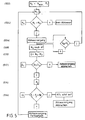
- the control unit 10 only initiates a discharge process or continues a discharge process started from the level N max only if the current level N 1 is greater than the predetermined level N v . This is done by venting compressed air from the air springs 2b, as already associated with the FIGS. 1 and 2 has been described. Immediately before the initiation of the discharge process is by means of the pressure sensor 24 (see FIG. 1 ), the pressure P 1 in the air springs is measured and passed to the control unit 10 (see steps 502, 504 and 506).
- the current level N 2 of the vehicle body relative to the rear axle of the motor vehicle is again measured with the aid of the height sensors 20 and 22.
- Corresponding signals are forwarded to the control unit 10, which determines from the signals the level N 2 of the vehicle body relative to the rear axle.
- a difference D N 1 - N 2 is determined in the control unit 10, which is thus a measure of how much the vehicle body has dropped in the period dt after initiation of the discharge process (see steps 508 and 510).
- the dimension D determined in this way is compared with a dimension D v determined in the control unit 10.
- the dimension D v is determined from design data such as discharge cross section, air spring volume, vehicle weight, etc., and again shows how the vehicle body would have to descend from the level N 1 present immediately before the discharge operation within the period of time dt after initiation of the discharge process, if the motor vehicle does not is in a critical situation. If the vehicle body has dropped at least by this amount D v in the period of time dt, ie if D is greater than or equal to D v , the discharge process is continued and with the aid of the pressure sensor 24 the current air pressure P 2 in the air springs 2 b is determined (see steps 512 and 514).
- the difference P 1 -P 2 of the pressure values is formed in the control unit 10. Based on the difference is checked in the control unit 10, how much the pressure P 1 has dropped within the time period dt. If the pressure difference is greater than a predetermined pressure difference dp, the z. B. from the slope of the curve in Fig. 4 derived, the control unit 10 concludes that the vehicle body is seated in the region of the rear axle of the motor vehicle. In this case, the control unit 10 aborts the discharge process. On the other hand, if the pressure P 1 has not dropped beyond the predetermined level dp, the discharge process is continued (see step 502).
- the current speed v M of the motor vehicle can be measured and compared in the control unit 10 with a predetermined speed V v . If the current speed v M of the motor vehicle is greater than the predetermined speed, there is no check of the discharge process according to steps 506 to 516 in the control unit 10. Rather, with the height sensors 20 and 22, only the current level of the vehicle body is monitored and the discharge process continues until it reaches the specified level.
- a check of the discharge process according to steps 506 to 516 takes place in the control unit only if the current speed of the vehicle is less than the predetermined speed v M.
- For the speed v M is preferably 5 km / h specified in the control unit 10.
Landscapes
- Engineering & Computer Science (AREA)
- Mechanical Engineering (AREA)
- Vehicle Body Suspensions (AREA)
Claims (13)
- Procédé pour commander ou réguler le niveau d'une carrosserie d'un véhicule automobile au moyen d'une installation de régulation de niveau avec des organes de commande (2a ; 2b), avec lesquels le niveau de la carrosserie du véhicule peut être abaissé en laissant s'échapper un fluide de commande hors des organes de commande (2a ; 2b) et avec une unité de commande (10), ayant les étapes de procédé suivantes :- le niveau de la carrosserie du véhicule est déterminé par rapport à un point de référence,- une opération de vidange au niveau de la carrosserie du véhicule est amorcée si le niveau déterminé est au-dessus d'un niveau prédéfini,caractérisé en ce que
l'on vérifie dans l'unité de commande (10), après l'amorçage de l'opération de vidange, si la carrosserie du véhicule est descendue conformément à une prescription initiale depuis le niveau déterminé immédiatement avant l'opération de vidange, de telle sorte que- l'on laisse s'échapper une petite quantité du fluide de commande d'un organe de commande, laquelle est considérablement plus petite que la quantité de fluide de commande que l'on a dû laisser s'échapper hors de l'organe de commande pour descendre la carrosserie du véhicule du niveau déterminé avant l'opération de vidange jusqu'au niveau prédéfini,- l'on vérifie, dans l'unité de commande (10), si la carrosserie du véhicule est descendue par rapport au niveau déterminé immédiatement avant l'opération de vidange, et en ce que- l'unité de commande (10) interrompt l'opération de vidange si ce n'est pas le cas. - Procédé selon la revendication 1, caractérisé en ce que la pression du fluide de commande ou les forces de support des roues sont détectées et l'unité de commande (10) interrompt alors aussi l'opération de vidange si la carrosserie du véhicule est descendue après une certaine période de temps, mais que la pression du fluide de commande ou au moins une force de support des roues a diminué au-delà d'une mesure prédéterminée.
- Procédé selon l'une quelconque des revendications 1 à 2, caractérisé en ce que- la période de temps est divisée en intervalles de temps et l'on vérifie si la carrosserie du véhicule est descendue pendant un intervalle de temps par rapport au niveau déterminé immédiatement avant l'opération de vidange, et- l'unité de commande (10) interrompt l'opération de vidange si ce n'est pas le cas.
- Procédé selon l'une quelconque des revendications 1 à 3, caractérisé en ce que- lorsque le niveau déterminé immédiatement avant l'opération de vidange correspond au niveau maximum ou approximativement au niveau maximum, l'unité de commande (10) interrompt l'opération de vidange si la carrosserie du véhicule, après une période de temps après laquelle elle aurait dû descendre depuis le niveau maximum même avec un chargement minimal, n'est pas descendue depuis le niveau déterminé immédiatement avant l'opération de vidange.
- Procédé selon l'une quelconque des revendications 1 ou 2, caractérisé en ce que- la période de temps est divisée en intervalles de temps et l'on vérifie, si, pendant un intervalle de temps, la carrosserie du véhicule est descendue d'au moins une mesure prédéfinie par rapport au niveau déterminé immédiatement avant l'opération de vidange, et si les forces de support des roues sont restées au moins presque identiques et- l'unité de commande (10) interrompt l'opération de vidange si ce n'est pas le cas.
- Procédé selon l'une quelconque des revendications 1 à 5, caractérisé en ce que l'installation de régulation de niveau contient au moins un ressort pneumatique (2a ; 2b) avec lequel la carrosserie du véhicule est montée à suspension, et en ce que pendant une opération de vidange, on laisse s'échapper de l'air sous pression hors du ressort pneumatique.
- Procédé selon la revendication 6, caractérisé en ce que- avant l'amorçage d'une opération de vidange, on détecte, au niveau d'au moins un ressort pneumatique (2a ; 2b) quelle est sa pression d'air,- on laisse s'échapper de l'air du ressort pneumatique (2a ; 2b) pendant une certaine période de temps jusqu'en dessous d'une pression d'air minimale dans le ressort pneumatique (2a ; 2b), cette pression minimale étant prédéfinie de telle sorte que la carrosserie du véhicule doive descendre même en cas de chargement minimal, depuis le niveau déterminé et- l'unité de commande (10) interrompt l'opération de vidange si ce n'est pas le cas jusqu'à la fin de la période de temps.
- Procédé selon la revendication 7, caractérisé en ce que la période de temps pendant laquelle on laisse s'échapper de l'air du ressort pneumatique (2a ; 2b) est choisie de telle sorte que la pression d'air dans le ressort pneumatique (2a ; 2b) chute pendant la période de temps depuis une pression d'air maximale pour un chargement maximal jusqu'en dessous de la pression d'air de chargement minimal.
- Procédé selon l'une quelconque des revendications 1 à 8, caractérisé en ce qu'il est mis en oeuvre seulement lorsque la vitesse du véhicule automobile est inférieure à une valeur prédéfinie.
- Procédé selon l'une quelconque des revendications 1 à 9, caractérisé en ce qu'après une interruption d'une opération de vidange lorsque le moteur du véhicule automobile est coupé, on peut effectuer une modification du niveau de la carrosserie du véhicule demandée par une personne seulement après le démarrage du moteur.
- Procédé selon l'une quelconque des revendications 1 à 10, caractérisé en ce qu'après une interruption d'une opération de vidange lorsque le moteur du véhicule automobile est démarré, on peut amorcer essentiellement exclusivement une opération de levage de la carrosserie du véhicule.
- Procédé selon l'une quelconque des revendications 10 ou 11, caractérisé en ce qu'une opération de vidange au niveau de la carrosserie du véhicule ne peut alors être réamorcée que si la vitesse du véhicule automobile dépasse une valeur limite ou si, après une coupure de l'allumage, une nouvelle réinitialisation de l'allumage a lieu.
- Procédé selon la revendication 12, caractérisé en ce qu'une opération de vidange au niveau de la carrosserie du véhicule ne peut alors être réamorcée que si le niveau déterminé actuellement est en outre en dessous du niveau maximal.
Applications Claiming Priority (2)
| Application Number | Priority Date | Filing Date | Title |
|---|---|---|---|
| DE19959012A DE19959012C5 (de) | 1999-12-08 | 1999-12-08 | Verfahren zur Steuerung bzw. Regelung des Niveaus eines Fahrzeugaufbaus eines Kraftfahrzeuges |
| DE19959012 | 1999-12-08 |
Publications (3)
| Publication Number | Publication Date |
|---|---|
| EP1106401A2 EP1106401A2 (fr) | 2001-06-13 |
| EP1106401A3 EP1106401A3 (fr) | 2004-04-21 |
| EP1106401B1 true EP1106401B1 (fr) | 2008-07-02 |
Family
ID=7931752
Family Applications (1)
| Application Number | Title | Priority Date | Filing Date |
|---|---|---|---|
| EP00125451A Expired - Lifetime EP1106401B1 (fr) | 1999-12-08 | 2000-11-21 | Procédé pour la commande ou la régulation du niveau de la carosserie d'un véhicule automobile |
Country Status (4)
| Country | Link |
|---|---|
| US (1) | US6471196B2 (fr) |
| EP (1) | EP1106401B1 (fr) |
| JP (1) | JP2001191777A (fr) |
| DE (2) | DE19959012C5 (fr) |
Cited By (1)
| Publication number | Priority date | Publication date | Assignee | Title |
|---|---|---|---|---|
| DE102018122242B3 (de) | 2018-09-12 | 2019-08-29 | Dr. Ing. H.C. F. Porsche Aktiengesellschaft | Verfahren zum Betreiben eines Kraftfahrzeugs |
Families Citing this family (26)
| Publication number | Priority date | Publication date | Assignee | Title |
|---|---|---|---|---|
| US7226057B2 (en) * | 2000-03-10 | 2007-06-05 | Days Corporation | Apparatus and method for automatically leveling an object |
| DE10160046B4 (de) * | 2000-12-30 | 2006-05-04 | Robert Bosch Gmbh | System und Verfahren zur Überwachung der Traktion eines Kraftfahrzeugs |
| DE10160972C1 (de) * | 2001-12-11 | 2003-01-23 | Daimler Chrysler Ag | Verfahren zur Regelung der Luftmenge in einem Niveauregulierungssystem |
| DE10225940B4 (de) * | 2002-06-11 | 2005-05-04 | Continental Aktiengesellschaft | Verfahren zur Regelung einer Niveauregelanlage und Niveauregelanlage |
| US8306696B2 (en) * | 2003-04-17 | 2012-11-06 | Driveright Holdings, Ltd. | Method and system for aligning a vehicle with an artificial horizon |
| PL1615787T3 (pl) * | 2003-04-17 | 2010-03-31 | Firestone Ind Products Co Llc | Sposób i układ do wyrównywania nieruchomego pojazdu względem sztucznego horyzontu |
| US7380799B2 (en) * | 2003-11-05 | 2008-06-03 | Bfs Diversified Products, Llc | Adjustable vehicle suspension system with adjustable-rate air spring |
| DE102004025340A1 (de) * | 2004-05-19 | 2005-12-15 | Continental Aktiengesellschaft | Verfahren zur Luftmengenregelung in einer geschlossenen Luftversorgungsanlage für ein Fahrwerk |
| US7146261B2 (en) * | 2004-06-03 | 2006-12-05 | Ford Global Technologies, Llc | Vehicle control system for exiting ruts |
| US7744099B2 (en) * | 2004-11-04 | 2010-06-29 | Driveright Holdings, Ltd. | Method and system for adjusting a vehicle aligned with an artificial horizon |
| DE102005023654A1 (de) * | 2005-05-23 | 2006-11-30 | Continental Aktiengesellschaft | Verfahren zur Bestimmung der Radaufstandskraft eines Kraftfahrzeuges |
| DE102006043608A1 (de) * | 2006-09-16 | 2008-03-27 | Continental Aktiengesellschaft | Verfahren zur Steuerung und/oder Regelung des Niveaus eines Fahrzeugaufbaus eines Kraftfahrzeuges |
| DE102006043607A1 (de) * | 2006-09-16 | 2008-03-27 | Continental Aktiengesellschaft | Verfahren zur Diagnose der Funktion einer Niveauregelanlage eines Kraftfahrzeugs |
| US8155835B2 (en) * | 2008-02-21 | 2012-04-10 | Driveright Holdings, Ltd. | Vehicle chassis height adjustment method and system |
| CA2636513C (fr) * | 2008-06-30 | 2011-06-28 | Aspen Custom Trailers Inc. | Suspension automatique |
| US20110093239A1 (en) * | 2009-10-21 | 2011-04-21 | Holbrook Gregory A | Vehicle weight sensing methods and systems |
| DE102009057529A1 (de) * | 2009-12-08 | 2011-06-09 | Iav Gmbh Ingenieurgesellschaft Auto Und Verkehr | Verfahren zur Steuerung der Niveauregulierung eines Fahrzeugaufbaus eines Kraftfahrzeuges |
| US8521361B2 (en) | 2010-08-17 | 2013-08-27 | Fourth Floor Associates, Inc. | Ride height control system and method for controlling load distribution at target ride height in a vehicle suspension system |
| DE102012112466B4 (de) * | 2012-12-18 | 2023-07-06 | Dr. Ing. H.C. F. Porsche Aktiengesellschaft | Vorrichtung zur Kompensation von Aufbaubewegungen |
| US9101519B2 (en) | 2013-02-07 | 2015-08-11 | Dallas Smith Corporation | Leveling ramp for a wheelchair |
| DE102013214306B4 (de) * | 2013-07-22 | 2023-06-07 | Bayerische Motoren Werke Aktiengesellschaft | Betriebsverfahren eines Niveauregelsystems eines Kraftfahrzeugs |
| DE102014112442B4 (de) | 2014-08-29 | 2019-07-11 | Dr. Ing. H.C. F. Porsche Aktiengesellschaft | Verfahren zur Regelung des Niveaus eines Fahrzeugaufbaus eines Kraftfahrzeuges |
| DE102016202475A1 (de) | 2016-02-18 | 2017-08-24 | Continental Automotive Gmbh | Fahrerassistenzvorrichtung, Fahrzeug mit der Fahrerassistenzvorrichtung sowie Verfahren zur Kollisionsvermeidung des Fahrzeugs mit einem kollisionsgefährdenden Fahrbahnabschnitt |
| JP6646732B2 (ja) | 2016-03-29 | 2020-02-14 | 日立オートモティブシステムズ株式会社 | 車高調整装置 |
| DE102017011753A1 (de) * | 2017-12-19 | 2019-06-19 | Wabco Gmbh | Verfahren zur Ermittlung einer Achslast an einem mechanisch und/oder pneumatisch/hydraulisch gefederten Fahrzeug sowie Vorrichtung hierzu |
| DE102022123743A1 (de) * | 2022-09-16 | 2024-03-21 | Zf Cv Systems Global Gmbh | Verfahren zum Betreiben einer Luftfederanlage, Computerprogramm und/oder computerlesbares Medium, Steuergerät und Nutzfahrzeug |
Family Cites Families (16)
| Publication number | Priority date | Publication date | Assignee | Title |
|---|---|---|---|---|
| DE3515017C2 (de) * | 1984-04-25 | 1994-02-03 | Mitsubishi Motors Corp | Niveausteuereinrichtung für ein Fahrzeug |
| JPS6294413A (ja) * | 1985-10-22 | 1987-04-30 | Mazda Motor Corp | 自動車の車高調整装置 |
| JPH0712084Y2 (ja) * | 1987-11-17 | 1995-03-22 | 株式会社ユニシアジェックス | 車高調整装置 |
| JPH01145217A (ja) * | 1987-11-30 | 1989-06-07 | Aisin Seiki Co Ltd | 車高調整制御の制御停止装置 |
| JP2724592B2 (ja) * | 1988-07-08 | 1998-03-09 | ダイハツ工業株式会社 | 車高調整装置 |
| US4965878A (en) * | 1988-11-30 | 1990-10-23 | Aisin Seiki Kabushiki Kaisha | Vehicle height control system |
| JP2509333B2 (ja) * | 1989-05-30 | 1996-06-19 | 日産自動車株式会社 | 車高制御装置 |
| JPH03178816A (ja) * | 1989-12-08 | 1991-08-02 | Suzuki Motor Corp | 車高調整装置 |
| JPH03273916A (ja) * | 1990-03-23 | 1991-12-05 | Mazda Motor Corp | 車両のサスペンション装置 |
| JP2969877B2 (ja) * | 1990-09-18 | 1999-11-02 | 日産自動車株式会社 | 車高調整装置 |
| JP2687703B2 (ja) * | 1990-09-18 | 1997-12-08 | 日産自動車株式会社 | 車高制御装置 |
| JPH0577622A (ja) * | 1991-05-24 | 1993-03-30 | Nissan Motor Co Ltd | 車高調整制御装置 |
| JPH07246820A (ja) * | 1994-03-14 | 1995-09-26 | Nissan Motor Co Ltd | 車高調整制御装置 |
| DE19505977C1 (de) * | 1995-02-21 | 1996-05-15 | Daimler Benz Ag | Fahrzeug mit pneumatisch gefederter Doppelachse |
| JP3644076B2 (ja) * | 1995-06-30 | 2005-04-27 | アイシン精機株式会社 | 車高制御装置 |
| US6173974B1 (en) * | 1999-09-28 | 2001-01-16 | Ford Global Technologies, Inc. | Detecting jacking or hoisting of a vehicle having a suspension system that includes gas levelers |
-
1999
- 1999-12-08 DE DE19959012A patent/DE19959012C5/de not_active Expired - Lifetime
-
2000
- 2000-11-21 EP EP00125451A patent/EP1106401B1/fr not_active Expired - Lifetime
- 2000-11-21 DE DE50015235T patent/DE50015235D1/de not_active Expired - Lifetime
- 2000-12-04 JP JP2000368436A patent/JP2001191777A/ja active Pending
- 2000-12-08 US US09/732,021 patent/US6471196B2/en not_active Expired - Lifetime
Cited By (1)
| Publication number | Priority date | Publication date | Assignee | Title |
|---|---|---|---|---|
| DE102018122242B3 (de) | 2018-09-12 | 2019-08-29 | Dr. Ing. H.C. F. Porsche Aktiengesellschaft | Verfahren zum Betreiben eines Kraftfahrzeugs |
Also Published As
| Publication number | Publication date |
|---|---|
| JP2001191777A (ja) | 2001-07-17 |
| US6471196B2 (en) | 2002-10-29 |
| DE19959012C5 (de) | 2008-09-11 |
| EP1106401A3 (fr) | 2004-04-21 |
| DE50015235D1 (de) | 2008-08-14 |
| US20010003386A1 (en) | 2001-06-14 |
| DE19959012A1 (de) | 2001-09-06 |
| DE19959012C2 (de) | 2003-06-26 |
| EP1106401A2 (fr) | 2001-06-13 |
Similar Documents
| Publication | Publication Date | Title |
|---|---|---|
| DE19959012C2 (de) | Verfahren zur Steuerung bzw. Regelung des Niveaus eines Fahrzeugaufbaus eines Kraftfahrzeuges | |
| EP2591928B1 (fr) | Réglage de la charge d'appui d'une remorque à essieu central | |
| DE10146724B4 (de) | Feststellung einer Radabhebung bei einem Kraftfahrzeug | |
| DE10160972C1 (de) | Verfahren zur Regelung der Luftmenge in einem Niveauregulierungssystem | |
| DE19622677C2 (de) | Fahrzeug mit niveaugeregeltem Federungssystem | |
| DE10331600B4 (de) | Verfahren zur Niveauregelung für pneumatische Niveauregelanlagen in Kraftfahrzeugen | |
| DE112007001089T5 (de) | Fahrzeugstabilitätssteuer- bzw. Regelsystem mit mehreren Empfindlichkeiten | |
| EP2070741A1 (fr) | Système de suspension pneumatique d'un véhicule | |
| DE69001946T2 (de) | Höhenregulierung bei einem aktiven Federungssystem. | |
| EP1571014B1 (fr) | Aide au démarrage pour un véhicule | |
| EP1744914B1 (fr) | Installation de regulation de niveau fermee destinee a un vehicule automobile | |
| EP2208624B1 (fr) | Installation de ressort pneumatique de remorque doté d'une limitation en hauteur | |
| DE102008021818B4 (de) | Verfahren zum Steuern einer Niveauregelanlage sowie Niveauregelanlage | |
| EP1650061B1 (fr) | Méthode pour changer le niveau d'un véhicule utilitaire avec système de suspension pneumatique | |
| EP1380454A1 (fr) | Méthode pour contrôler le niveau de chassis du vehicule | |
| EP3647085B1 (fr) | Véhicule automobile et procédé d'ajustement de la hauteur d'un véhicule automobile réglable en hauteur | |
| DE102017006278B4 (de) | Verfahren zum Betreiben eines elektronisch steuerbaren Luftfedersystems in einem Fahrzeug sowie elektronisch steuerbares Luftfedersystem | |
| DE112005003020T5 (de) | Rad für Fahrzeug und System zur Überprüfung seines Auffülldrucks | |
| EP1928676B1 (fr) | Systeme de correction d'assiette de vehicule et procede de fonctionnement associe | |
| EP2390121A1 (fr) | Remorque de véhicule utilitaire et dispositif de commande pour agencement de ressort pneumatique | |
| DE102015003589B4 (de) | Verfahren und System zur Erleichterung der Be- und Entladung eines Kraftfahrzeugs | |
| DE102023116790A1 (de) | Freizeitfahrzeug mit einer Hubstützenvorrichtung sowie Verfahren zur Bestimmung von Achslasten des Freizeitfahrzeugs | |
| DE102012001243A1 (de) | Verfahren und Steuersystem zur Verhinderung der Verengung von Luftfederungsbälgen bei Fahrzeugen | |
| DE102013008655B4 (de) | Verfahren zur Niveauregelung eines luftgefederten Kraftfahrzeugs | |
| WO2005108147A1 (fr) | Dispositif et procede pour remedier aux problemes de traction dans des vehicules a essieux multiples |
Legal Events
| Date | Code | Title | Description |
|---|---|---|---|
| PUAI | Public reference made under article 153(3) epc to a published international application that has entered the european phase |
Free format text: ORIGINAL CODE: 0009012 |
|
| AK | Designated contracting states |
Kind code of ref document: A2 Designated state(s): AT BE CH CY DE DK ES FI FR GB GR IE IT LI LU MC NL PT SE TR |
|
| AX | Request for extension of the european patent |
Free format text: AL;LT;LV;MK;RO;SI |
|
| 17P | Request for examination filed |
Effective date: 20031218 |
|
| PUAL | Search report despatched |
Free format text: ORIGINAL CODE: 0009013 |
|
| AK | Designated contracting states |
Kind code of ref document: A3 Designated state(s): AT BE CH CY DE DK ES FI FR GB GR IE IT LI LU MC NL PT SE TR |
|
| AX | Request for extension of the european patent |
Extension state: AL LT LV MK RO SI |
|
| RIC1 | Information provided on ipc code assigned before grant |
Ipc: 7B 60G 17/052 B Ipc: 7B 60G 17/015 A |
|
| 17Q | First examination report despatched |
Effective date: 20040503 |
|
| AKX | Designation fees paid |
Designated state(s): DE ES FR GB IT SE |
|
| GRAP | Despatch of communication of intention to grant a patent |
Free format text: ORIGINAL CODE: EPIDOSNIGR1 |
|
| GRAS | Grant fee paid |
Free format text: ORIGINAL CODE: EPIDOSNIGR3 |
|
| GRAA | (expected) grant |
Free format text: ORIGINAL CODE: 0009210 |
|
| AK | Designated contracting states |
Kind code of ref document: B1 Designated state(s): DE ES FR GB IT SE |
|
| REG | Reference to a national code |
Ref country code: GB Ref legal event code: FG4D Free format text: NOT ENGLISH |
|
| REF | Corresponds to: |
Ref document number: 50015235 Country of ref document: DE Date of ref document: 20080814 Kind code of ref document: P |
|
| PG25 | Lapsed in a contracting state [announced via postgrant information from national office to epo] |
Ref country code: ES Free format text: LAPSE BECAUSE OF FAILURE TO SUBMIT A TRANSLATION OF THE DESCRIPTION OR TO PAY THE FEE WITHIN THE PRESCRIBED TIME-LIMIT Effective date: 20081013 |
|
| PLBE | No opposition filed within time limit |
Free format text: ORIGINAL CODE: 0009261 |
|
| STAA | Information on the status of an ep patent application or granted ep patent |
Free format text: STATUS: NO OPPOSITION FILED WITHIN TIME LIMIT |
|
| 26N | No opposition filed |
Effective date: 20090403 |
|
| PG25 | Lapsed in a contracting state [announced via postgrant information from national office to epo] |
Ref country code: IT Free format text: LAPSE BECAUSE OF FAILURE TO SUBMIT A TRANSLATION OF THE DESCRIPTION OR TO PAY THE FEE WITHIN THE PRESCRIBED TIME-LIMIT Effective date: 20080702 |
|
| PG25 | Lapsed in a contracting state [announced via postgrant information from national office to epo] |
Ref country code: SE Free format text: LAPSE BECAUSE OF FAILURE TO SUBMIT A TRANSLATION OF THE DESCRIPTION OR TO PAY THE FEE WITHIN THE PRESCRIBED TIME-LIMIT Effective date: 20081002 |
|
| PGFP | Annual fee paid to national office [announced via postgrant information from national office to epo] |
Ref country code: GB Payment date: 20091119 Year of fee payment: 10 |
|
| REG | Reference to a national code |
Ref country code: DE Ref legal event code: R081 Ref document number: 50015235 Country of ref document: DE Owner name: CONTINENTAL TEVES AG & CO. OHG, DE Free format text: FORMER OWNER: CONTINENTAL AKTIENGESELLSCHAFT, 30165 HANNOVER, DE Effective date: 20110414 |
|
| GBPC | Gb: european patent ceased through non-payment of renewal fee |
Effective date: 20101121 |
|
| PG25 | Lapsed in a contracting state [announced via postgrant information from national office to epo] |
Ref country code: GB Free format text: LAPSE BECAUSE OF NON-PAYMENT OF DUE FEES Effective date: 20101121 |
|
| REG | Reference to a national code |
Ref country code: FR Ref legal event code: PLFP Year of fee payment: 16 |
|
| REG | Reference to a national code |
Ref country code: FR Ref legal event code: PLFP Year of fee payment: 17 |
|
| REG | Reference to a national code |
Ref country code: FR Ref legal event code: PLFP Year of fee payment: 18 |
|
| PGFP | Annual fee paid to national office [announced via postgrant information from national office to epo] |
Ref country code: DE Payment date: 20181130 Year of fee payment: 19 |
|
| PGFP | Annual fee paid to national office [announced via postgrant information from national office to epo] |
Ref country code: FR Payment date: 20181121 Year of fee payment: 19 |
|
| REG | Reference to a national code |
Ref country code: DE Ref legal event code: R119 Ref document number: 50015235 Country of ref document: DE |
|
| PG25 | Lapsed in a contracting state [announced via postgrant information from national office to epo] |
Ref country code: DE Free format text: LAPSE BECAUSE OF NON-PAYMENT OF DUE FEES Effective date: 20200603 Ref country code: FR Free format text: LAPSE BECAUSE OF NON-PAYMENT OF DUE FEES Effective date: 20191130 |