EP1106426B1 - Appui-tête pivotant - Google Patents
Appui-tête pivotant Download PDFInfo
- Publication number
- EP1106426B1 EP1106426B1 EP00126116A EP00126116A EP1106426B1 EP 1106426 B1 EP1106426 B1 EP 1106426B1 EP 00126116 A EP00126116 A EP 00126116A EP 00126116 A EP00126116 A EP 00126116A EP 1106426 B1 EP1106426 B1 EP 1106426B1
- Authority
- EP
- European Patent Office
- Prior art keywords
- portions
- headrest
- stay
- frame body
- plate bodies
- Prior art date
- Legal status (The legal status is an assumption and is not a legal conclusion. Google has not performed a legal analysis and makes no representation as to the accuracy of the status listed.)
- Expired - Lifetime
Links
Images


Classifications
-
- B—PERFORMING OPERATIONS; TRANSPORTING
- B60—VEHICLES IN GENERAL
- B60N—SEATS SPECIALLY ADAPTED FOR VEHICLES; VEHICLE PASSENGER ACCOMMODATION NOT OTHERWISE PROVIDED FOR
- B60N2/00—Seats specially adapted for vehicles; Arrangement or mounting of seats in vehicles
- B60N2/80—Head-rests
- B60N2/806—Head-rests movable or adjustable
- B60N2/838—Tiltable
- B60N2/841—Tiltable characterised by their locking devices
- B60N2/847—Tiltable characterised by their locking devices with stepwise positioning
Definitions
- the present invention provides a headrest device according to claim 1.
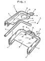
- a plurality of protruding portions 10 which bulge inwardly are formed on an inner peripheral surface of the support portion 6. These protruding portions 10 are brought into friction contact with an outer peripheral surface of the connecting portion 5 of the stay 2 thus providing a frictional movement of the headrest (see Fig. 4).
- portions of respective plate bodies 3, 3 may be brought into contact with each other and are adhered to each other by a spot welding.
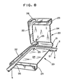
- a headrest frame body is produced by forming a pair of frame portions 20 by molding a sheet of metal plate with a press.
- a pair of frame portions 20 have the equal shape and respective frame portions 20 are arranged in the left-and-right (or front-and-rear) symmetry.
- the side groove portions 22 have a shape for receiving leg member portions, that is, leg portions 4 of the stay 2.
- the side groove portions 22 preferably increases the depth of the groove as the side groove portions 22 move in the downward direction such that the side groove portions 22 have a triangular shape when viewed from both sides thereof.
Landscapes
- Engineering & Computer Science (AREA)
- Aviation & Aerospace Engineering (AREA)
- Transportation (AREA)
- Mechanical Engineering (AREA)
- Chair Legs, Seat Parts, And Backrests (AREA)
- Seats For Vehicles (AREA)
Claims (5)
- Dispositif d'appuie-tête (1) incluant un étai en forme de U inversé (2) ayant des portions d'organes de jambes opposées (4) adaptées pour être maintenues par un cadre arrière d'un siège d'un véhicule et une portion de connexion (5) qui relie les portions d'organes de jambes (4), un corps de cadre d'appuie-tête qui est soutenu sur l'étai (2) de manière à ce que le corps de cadre d'appuie-tête soit rotatif dans les directions de va-et-vient autour de la portion de connexion (5) de l'étai (2), et un coussin d'appuie-tête,
où le corps de cadre d'appuie-tête est composé d'une paire de corps de plaques opposés (3, 3), qui comprennent chacun une portion de support (6) ayant une coupe transversale approximativement semi-circulaire qui a une portion rentrant en contact avec la portion de connexion (5) de l'étai (2) et des portions de restriction (7, 7) qui couvrent les portions d'organes de jambes (4) de l'étai (2) et limitent la rotation du corps de cadre d'appuie-tête autour de la portion de connexion (5) de l'étai (2), les deux corps de plaques (3, 3) ayant une relation où les deux plaques ont des portions de support (6,6) et des portions de restriction (7, 7) correspondantes opposées les unes aux autres et sécurisées de manière fixe les unes aux autres,
les portions de restriction (7, 7) des corps de plaques (3, 3) ont une coupe transversale approximativement en forme de U et des surfaces latérales triangulaires qui ont une largeur plus grande à des extrémités libres correspondantes,
caractérisé en ce que
des portions périphériques des extrémités libres ont des portions de brides (11) inclinées vers les portions d'organes de jambes (4) et pourvues le long de toutes les circonférences des portions périphériques des extrémités libres, et
le coussin d'appuie-tête fait par une résine mousse est intégralement formé avec le corps de cadre d'appuie-tête par un moulage de mousse. - Dispositif d'appuie-tête (1) selon la revendication 1, dans lequel des surfaces périphériques internes des portions de support (6, 6) des corps de plaques (3, 3) ont des portions en protubérance (10) qui sont bombées vers l'intérieur et les portions en protubérance (10) sont mises en contact avec une surface périphérique externe de la portion de connexion (5) de l'étai (2).
- Dispositif d'appuie-tête (1) selon la revendication 1, dans lequel les corps de plaques (3, 3) ont des portions planaires (9, 9) entre les deux portions de restriction (7, 7) et les deux portions planaires (9, 9) qui sont opposées l'une à l'autre sont reliées par un matage.
- Dispositif d'appuie-tête (1) selon la revendication 3, dans lequel une paire de corps de plaques (3, 3) ont la forme égale.
- Dispositif d'appuie-tête (1) selon la revendication 1, dans lequel des surfaces de parois internes qui définissent des portions d'espaces internes des portions de restriction (7, 7) ont une forme ondulée.
Applications Claiming Priority (2)
| Application Number | Priority Date | Filing Date | Title |
|---|---|---|---|
| JP33979099A JP4272319B2 (ja) | 1999-11-30 | 1999-11-30 | ヘッドレスト装置 |
| JP33979099 | 1999-11-30 |
Publications (3)
| Publication Number | Publication Date |
|---|---|
| EP1106426A2 EP1106426A2 (fr) | 2001-06-13 |
| EP1106426A3 EP1106426A3 (fr) | 2003-09-10 |
| EP1106426B1 true EP1106426B1 (fr) | 2008-01-02 |
Family
ID=18330840
Family Applications (1)
| Application Number | Title | Priority Date | Filing Date |
|---|---|---|---|
| EP00126116A Expired - Lifetime EP1106426B1 (fr) | 1999-11-30 | 2000-11-29 | Appui-tête pivotant |
Country Status (4)
| Country | Link |
|---|---|
| US (1) | US6412872B2 (fr) |
| EP (1) | EP1106426B1 (fr) |
| JP (1) | JP4272319B2 (fr) |
| DE (1) | DE60037633T2 (fr) |
Families Citing this family (34)
| Publication number | Priority date | Publication date | Assignee | Title |
|---|---|---|---|---|
| JP4411715B2 (ja) * | 2000-01-28 | 2010-02-10 | アイシン精機株式会社 | ヘッドレスト装置 |
| JP4465782B2 (ja) | 2000-02-29 | 2010-05-19 | アイシン精機株式会社 | ヘッドレスト装置 |
| US20050127734A1 (en) * | 2003-12-16 | 2005-06-16 | Lear Corporation | Energy management head restraint insert |
| US7537282B2 (en) * | 2003-12-16 | 2009-05-26 | Lear Corporation | Head restraint arrangement for a vehicle seat and a method of manufacture |
| USD536566S1 (en) * | 2004-04-28 | 2007-02-13 | Burch S Arthur | School bus seat back envelope cushion |
| US7338119B2 (en) | 2004-09-30 | 2008-03-04 | Selwyn Arthur Burch | School bus seat with energy absorber |
| US7740322B2 (en) * | 2004-09-30 | 2010-06-22 | Selwyn Arthur Burch | School bus seat with energy absorber |
| US8647544B2 (en) * | 2004-09-30 | 2014-02-11 | Selwyn Arthur Burch | Method for manufacturing school bus seat with energy absorber and using same |
| DE102005015292B3 (de) * | 2005-04-01 | 2006-11-30 | Johnson Controls Gmbh | Kopfstütze für ein Fahrzeug, Verfahren zur Herstellung einer Kopfstütze und Fahrzeugsitz |
| JP2008253333A (ja) * | 2007-03-31 | 2008-10-23 | T S Tec Kk | ヘッドレスト及び該ヘッドレストを備えた車両用シート |
| JP5059485B2 (ja) * | 2007-05-25 | 2012-10-24 | 有限会社オダ技商 | ヘッドレスト装置 |
| US20090167069A1 (en) * | 2007-12-28 | 2009-07-02 | Tachi-S Co., Ltd. | Inclinable headrest |
| KR200451797Y1 (ko) | 2008-06-13 | 2011-01-12 | 정해일 | 헤드레스트의 각도 조절장치 |
| JP5428308B2 (ja) * | 2008-11-28 | 2014-02-26 | 東海化成工業株式会社 | ヘッドレスト装置 |
| US7931331B2 (en) * | 2009-03-26 | 2011-04-26 | Faurecia Automotive Seating, Inc. | Headrest with energy dissipater for rear passenger |
| US8322790B2 (en) * | 2009-04-08 | 2012-12-04 | Lear Corporation | Seat assembly having a multi-position head restraint assembly |
| FR2947777B1 (fr) * | 2009-07-09 | 2011-07-22 | Faurecia Sieges D Automobiles | Appui-tete de siege d'automobile comportant des elements articules entre eux avec friction. |
| US8163704B2 (en) * | 2009-10-20 | 2012-04-24 | Novartis Ag | Glycoside derivatives and uses thereof |
| JP5685026B2 (ja) * | 2010-07-30 | 2015-03-18 | 日本テクニカ株式会社 | ヘッドレストブラケットの支持構造 |
| DE102012012684B3 (de) * | 2012-06-27 | 2013-11-21 | Johnson Controls Gmbh | Befestigungsanordnung, kopfstütze und montageverfahren |
| USD699959S1 (en) | 2012-09-20 | 2014-02-25 | Steelcase Inc. | Chair |
| USD781605S1 (en) | 2015-04-24 | 2017-03-21 | Steelcase Inc. | Chair |
| FR3003211B1 (fr) * | 2013-03-18 | 2015-05-01 | Cera | Appui-tete de siege de vehicule automobile |
| DE102013208316B3 (de) * | 2013-05-07 | 2014-05-15 | Lear Corp. | Kopfstützen-Befestigungssystem |
| US9174559B2 (en) * | 2013-07-16 | 2015-11-03 | Bose Corporation | Headrest |
| EP3154819B8 (fr) * | 2014-06-16 | 2019-04-17 | Safran Seats USA LLC | Appuie-tête leger avec maille de suspension et châssis de support |
| USD760526S1 (en) | 2015-04-24 | 2016-07-05 | Steelcase Inc. | Headrest assembly |
| USD759415S1 (en) | 2015-04-24 | 2016-06-21 | Steelcase Inc. | Headrest |
| USD758774S1 (en) | 2015-04-24 | 2016-06-14 | Steelcase Inc. | Headrest assembly |
| USD781604S1 (en) | 2015-04-24 | 2017-03-21 | Steelcase Inc. | Chair |
| CN115996863A (zh) * | 2020-08-31 | 2023-04-21 | 提爱思科技股份有限公司 | 头枕 |
| KR20220087996A (ko) * | 2020-12-18 | 2022-06-27 | 현대자동차주식회사 | 충돌성능이 개선된 차량의 헤드레스트 |
| CN116424188A (zh) * | 2023-04-26 | 2023-07-14 | 重庆宏汇汽车部件有限公司 | 一种汽车座椅头枕侧翼电动调节机构 |
| US12485805B2 (en) * | 2023-07-12 | 2025-12-02 | Matsumoto Industry Co., Ltd. | Coupling structure between headrest stay and core member, headrest, and method for manufacturing the same |
Family Cites Families (24)
| Publication number | Priority date | Publication date | Assignee | Title |
|---|---|---|---|---|
| DE2405774B2 (de) * | 1974-02-07 | 1980-09-18 | Gebr. Happich Gmbh, 5600 Wuppertal | Kopfstütze für Fahrzeugsitze |
| DE2734506A1 (de) * | 1977-07-30 | 1979-02-15 | Happich Gmbh Gebr | Kopfstuetze |
| JPS61113653U (fr) | 1984-12-28 | 1986-07-18 | ||
| JPS62207409A (ja) * | 1986-03-06 | 1987-09-11 | 田中 永一郎 | 頸椎サポ−ト付き自動車用ヘツドレスト |
| DE3625691A1 (de) * | 1986-07-30 | 1988-02-04 | Fhs Stahlverformung Gmbh | Hoehen- und neigungsverstellbare kopfstuetze mit mittlerem fenster fuer kraftfahrzeugsitze |
| US4720146A (en) | 1986-08-28 | 1988-01-19 | General Motors Corporation | Vehicle seat headrest apparatus and method |
| JPH0414045Y2 (fr) | 1987-06-30 | 1992-03-31 | ||
| US5316372A (en) | 1987-09-10 | 1994-05-31 | Ford Motor Company | Headrest for a motor vehicle |
| US4861107A (en) | 1988-06-13 | 1989-08-29 | Hoover Universal, Inc. | Head rest with forwardly pivotable pad mounted on friction hinge |
| US4840428A (en) | 1988-06-24 | 1989-06-20 | Tachi-S Co., Ltd. | Head rest adjusting device |
| US5181763A (en) * | 1990-09-20 | 1993-01-26 | Ronald P. Dellanno | Apparatus for preventing whiplash |
| US5257853A (en) * | 1992-02-07 | 1993-11-02 | Hoover Universal, Inc. | Headrest armature for seats |
| JPH05269030A (ja) | 1992-03-23 | 1993-10-19 | Eiichiro Tanaka | ヘッドレスト |
| DE4239272A1 (de) | 1992-11-23 | 1994-05-26 | Hammerstein Gmbh C Rob | Kopfstütze für einen Kraftfahrzeugsitz |
| JP3221207B2 (ja) | 1994-02-23 | 2001-10-22 | アイシン精機株式会社 | ヘツドレスト装置 |
| JPH07289387A (ja) | 1994-04-21 | 1995-11-07 | Aisin Seiki Co Ltd | ヘツドレスト装置 |
| JP3694936B2 (ja) | 1995-04-20 | 2005-09-14 | トヨタ紡織株式会社 | 可倒式ヘッドレスト |
| JP3827352B2 (ja) * | 1995-11-28 | 2006-09-27 | 株式会社イノアックコーポレーション | 自動車用ヘッドレスト |
| JP3564834B2 (ja) | 1995-11-30 | 2004-09-15 | アイシン精機株式会社 | ヘッドレスト装置 |
| DE19548339C2 (de) | 1995-12-22 | 1998-05-28 | Daimler Benz Ag | Kopfstütze für einen Fahrzeugsitz |
| IT1284666B1 (it) | 1996-07-16 | 1998-05-21 | Bruzolo Manifatt Gestind Mb | Appoggiatesta per sedili di autoveicoli. |
| DE29614238U1 (de) | 1996-08-16 | 1996-12-12 | Trw Occupant Restraint Systems Gmbh, 73551 Alfdorf | Kopfstütze für einen Fahrzeugsitz |
| DE19739131C1 (de) | 1997-09-06 | 1998-12-10 | Daimler Benz Ag | Kopfstütze für einen Fahrzeugsitz |
| CA2273692C (fr) * | 1998-06-03 | 2007-10-02 | Magna Interior Systems Inc. | Methode de fabrication d'une piece interieure de vehicule et composants fabriques selon cette methode |
-
1999
- 1999-11-30 JP JP33979099A patent/JP4272319B2/ja not_active Expired - Fee Related
-
2000
- 2000-11-29 DE DE60037633T patent/DE60037633T2/de not_active Expired - Lifetime
- 2000-11-29 EP EP00126116A patent/EP1106426B1/fr not_active Expired - Lifetime
- 2000-11-30 US US09/725,723 patent/US6412872B2/en not_active Expired - Fee Related
Also Published As
| Publication number | Publication date |
|---|---|
| DE60037633D1 (de) | 2008-02-14 |
| US6412872B2 (en) | 2002-07-02 |
| US20010004167A1 (en) | 2001-06-21 |
| EP1106426A3 (fr) | 2003-09-10 |
| JP4272319B2 (ja) | 2009-06-03 |
| EP1106426A2 (fr) | 2001-06-13 |
| DE60037633T2 (de) | 2009-01-08 |
| JP2001149168A (ja) | 2001-06-05 |
Similar Documents
| Publication | Publication Date | Title |
|---|---|---|
| EP1106426B1 (fr) | Appui-tête pivotant | |
| JPH0645415Y2 (ja) | 自動車のステアリング装置における衝撃エネルギ吸収機構 | |
| EP2193976A2 (fr) | Système de colonne de direction | |
| KR100442302B1 (ko) | 차량용 시이트의 회전 및 조정 기구 | |
| US5588703A (en) | Lumbar support device for vehicle seat | |
| US7918483B2 (en) | Adjustable steering column for a motor vehicle | |
| GB2297607A (en) | Clamp arrangement for an adjustable steering column | |
| KR20190078358A (ko) | 차량용 시트 펌핑 장치 | |
| JP2010126142A (ja) | ステアリングコラム装置 | |
| JP4207799B2 (ja) | 衝撃吸収式ステアリングコラム装置 | |
| JP3175529B2 (ja) | 衝撃吸収ステアリング装置 | |
| CN110446647A (zh) | 转向装置 | |
| JP2014118002A (ja) | アクスルハウジングの取付構造 | |
| JP2013018372A (ja) | サイドサポート装置 | |
| KR970003876Y1 (ko) | 자동차 시이 백의 럼버 서포트 취부구조 | |
| KR101885022B1 (ko) | 자동차의 조향컬럼 | |
| JPH07285354A (ja) | シフトレバー装置 | |
| JPH0620165U (ja) | 衝撃吸収ステアリング装置 | |
| JPH0240835Y2 (fr) | ||
| JPH0356105Y2 (fr) | ||
| JP2001149169A (ja) | ヘッドレスト装置 | |
| JPH0679690U (ja) | エネルギ吸収式ステアリング装置 | |
| JP2006347462A (ja) | ステアリング装置 | |
| JP2024039500A (ja) | 車両用シート | |
| JPH0744525Y2 (ja) | エネルギー吸収式ステアリングコラム |
Legal Events
| Date | Code | Title | Description |
|---|---|---|---|
| PUAI | Public reference made under article 153(3) epc to a published international application that has entered the european phase |
Free format text: ORIGINAL CODE: 0009012 |
|
| 17P | Request for examination filed |
Effective date: 20001129 |
|
| AK | Designated contracting states |
Kind code of ref document: A2 Designated state(s): AT BE CH CY DE DK ES FI FR GB GR IE IT LI LU MC NL PT SE TR |
|
| AX | Request for extension of the european patent |
Free format text: AL;LT;LV;MK;RO;SI |
|
| PUAL | Search report despatched |
Free format text: ORIGINAL CODE: 0009013 |
|
| AK | Designated contracting states |
Kind code of ref document: A3 Designated state(s): AT BE CH CY DE DK ES FI FR GB GR IE IT LI LU MC NL PT SE TR |
|
| AX | Request for extension of the european patent |
Extension state: AL LT LV MK RO SI |
|
| RIC1 | Information provided on ipc code assigned before grant |
Ipc: 7B 60N 2/48 A Ipc: 7A 47C 7/38 B |
|
| AKX | Designation fees paid |
Designated state(s): DE FR GB |
|
| 17Q | First examination report despatched |
Effective date: 20050726 |
|
| GRAP | Despatch of communication of intention to grant a patent |
Free format text: ORIGINAL CODE: EPIDOSNIGR1 |
|
| GRAS | Grant fee paid |
Free format text: ORIGINAL CODE: EPIDOSNIGR3 |
|
| GRAA | (expected) grant |
Free format text: ORIGINAL CODE: 0009210 |
|
| AK | Designated contracting states |
Kind code of ref document: B1 Designated state(s): DE FR GB |
|
| REG | Reference to a national code |
Ref country code: GB Ref legal event code: FG4D |
|
| REF | Corresponds to: |
Ref document number: 60037633 Country of ref document: DE Date of ref document: 20080214 Kind code of ref document: P |
|
| ET | Fr: translation filed | ||
| PLBE | No opposition filed within time limit |
Free format text: ORIGINAL CODE: 0009261 |
|
| STAA | Information on the status of an ep patent application or granted ep patent |
Free format text: STATUS: NO OPPOSITION FILED WITHIN TIME LIMIT |
|
| 26N | No opposition filed |
Effective date: 20081003 |
|
| GBPC | Gb: european patent ceased through non-payment of renewal fee |
Effective date: 20081129 |
|
| PG25 | Lapsed in a contracting state [announced via postgrant information from national office to epo] |
Ref country code: GB Free format text: LAPSE BECAUSE OF NON-PAYMENT OF DUE FEES Effective date: 20081129 |
|
| PGFP | Annual fee paid to national office [announced via postgrant information from national office to epo] |
Ref country code: FR Payment date: 20141110 Year of fee payment: 15 Ref country code: DE Payment date: 20141125 Year of fee payment: 15 |
|
| REG | Reference to a national code |
Ref country code: DE Ref legal event code: R119 Ref document number: 60037633 Country of ref document: DE |
|
| REG | Reference to a national code |
Ref country code: FR Ref legal event code: ST Effective date: 20160729 |
|
| PG25 | Lapsed in a contracting state [announced via postgrant information from national office to epo] |
Ref country code: DE Free format text: LAPSE BECAUSE OF NON-PAYMENT OF DUE FEES Effective date: 20160601 |
|
| PG25 | Lapsed in a contracting state [announced via postgrant information from national office to epo] |
Ref country code: FR Free format text: LAPSE BECAUSE OF NON-PAYMENT OF DUE FEES Effective date: 20151130 |