EP1106427A1 - Verstellbare Schlafstütze für Beifahrersitz - Google Patents
Verstellbare Schlafstütze für Beifahrersitz Download PDFInfo
- Publication number
- EP1106427A1 EP1106427A1 EP99450029A EP99450029A EP1106427A1 EP 1106427 A1 EP1106427 A1 EP 1106427A1 EP 99450029 A EP99450029 A EP 99450029A EP 99450029 A EP99450029 A EP 99450029A EP 1106427 A1 EP1106427 A1 EP 1106427A1
- Authority
- EP
- European Patent Office
- Prior art keywords
- sleep
- rod
- tube
- arm
- passenger
- Prior art date
- Legal status (The legal status is an assumption and is not a legal conclusion. Google has not performed a legal analysis and makes no representation as to the accuracy of the status listed.)
- Withdrawn
Links
- 230000000903 blocking effect Effects 0.000 claims description 7
- 238000006073 displacement reaction Methods 0.000 claims description 2
- 210000003423 ankle Anatomy 0.000 claims 1
- 230000004438 eyesight Effects 0.000 abstract description 3
- 210000003128 head Anatomy 0.000 description 26
- 230000006978 adaptation Effects 0.000 description 4
- 241001417494 Sciaenidae Species 0.000 description 2
- 230000000694 effects Effects 0.000 description 2
- 206010041349 Somnolence Diseases 0.000 description 1
- 230000004308 accommodation Effects 0.000 description 1
- 230000006835 compression Effects 0.000 description 1
- 238000007906 compression Methods 0.000 description 1
- 210000001061 forehead Anatomy 0.000 description 1
- 210000002414 leg Anatomy 0.000 description 1
- 210000004417 patella Anatomy 0.000 description 1
Images





Classifications
-
- B—PERFORMING OPERATIONS; TRANSPORTING
- B60—VEHICLES IN GENERAL
- B60N—SEATS SPECIALLY ADAPTED FOR VEHICLES; VEHICLE PASSENGER ACCOMMODATION NOT OTHERWISE PROVIDED FOR
- B60N2/00—Seats specially adapted for vehicles; Arrangement or mounting of seats in vehicles
- B60N2/80—Head-rests
- B60N2/885—Head-rests provided with side-rests
-
- B—PERFORMING OPERATIONS; TRANSPORTING
- B60—VEHICLES IN GENERAL
- B60N—SEATS SPECIALLY ADAPTED FOR VEHICLES; VEHICLE PASSENGER ACCOMMODATION NOT OTHERWISE PROVIDED FOR
- B60N2/00—Seats specially adapted for vehicles; Arrangement or mounting of seats in vehicles
- B60N2/80—Head-rests
- B60N2/806—Head-rests movable or adjustable
- B60N2/838—Tiltable
-
- B—PERFORMING OPERATIONS; TRANSPORTING
- B60—VEHICLES IN GENERAL
- B60N—SEATS SPECIALLY ADAPTED FOR VEHICLES; VEHICLE PASSENGER ACCOMMODATION NOT OTHERWISE PROVIDED FOR
- B60N2/00—Seats specially adapted for vehicles; Arrangement or mounting of seats in vehicles
- B60N2/80—Head-rests
- B60N2/882—Head-rests detachable
Definitions
- the invention relates to a retractable lateral headrest for a passenger seat.
- the object of the invention is to provide a retractable lateral headrest provided with means adjusting the position of the head restraint, in particular the lateral tilt of the the head restraint and the distance between the head restraint and the seat, and provided with means for avoid sliding the passenger's head forward or down.
- the lateral headrest according to the invention was designed to be able to support the temple of the passenger in different positions and in particular in the position described above.
- the retractable side headrest according to the invention will be referred to as "Temple support”.
- the temple support according to the invention is intended to equip the seats with passengers, but in no case the driver's seats.
- the value of the angle B characterizes the adaptation, in the “sleep” position, of the temple support to the rotation of the head around the atlas-bregma axis.
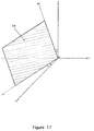
- the value of the angle C characterizes the adaptation, in the “sleep” position, of the temple support to the inclination lateral of the head, the said lateral inclination manifested by a rotation of the head of the passenger around the anteroposterior nuqual axis.
- the angle C is equal to zero. According to the invention, the angle C is adjustable from 0 to 90 degrees, which allows better adaptation of the temple support to the position of the sleeping passenger's head.
- the temple support is provided with means which, in the "sleep” position, prevent the passenger's head from sliding forward or down.
- the temple support is provided with means which, in the “sleep” position, make it possible to adjust the distance between the temple support and the backrest. Said means allow the user to position the temple support in the position he deems the most comfortable.
- FIG. 1b shows in perspective, seen from the front of the vehicle, a headrest posterior fitted with the temple support, the said temple support being represented in position "Awakening”.
- the sliding tube (4) is shown in a position such that the central part (39) of the bearing surface (5) is in a vertical plane.
- the padding (42) of the bearing surface (5) is not shown in the Figure 2.
- the tube (4) can rotate around the arm (2), which adjusts the inclination of the surface (5).
- the tube (4) can slide along the arm (2), which allows you to adjust the distance between the surface (5) and the fixing device (1).
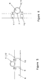
- Figure 3 shows, schematically in perspective, a rear view of the means fixing the bar (6) to a vertical upright.
- the half-necklace (12) is not shown in FIG. 3.
- Figure 4 shows the bar (6) in top view, as well as sections of the said bar (6), the said cuts being situated at the level of the flat (7), at the level of the middle of the bar (6), at the threaded orifice (24) and at the orifice (23).
- the bar (6) has on its front face two flats (7) and (8).
- the two flats (7) and (8) are opposite the rear sides of the vertical uprights of the head restraint posterior.
- FIG. 6 shows, in side view, a fixing means from the bar (6) to a vertical upright.
- the flat (7) is in contact with the upright vertical.
- the half-collars are arranged vertically behind the bar (6).
- the half-collars (11) and (12) are arranged horizontally in front of the vertical upright.
- This fixing device has the advantage that it can be used on most headrests known hindquarters.
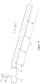
- FIG. 7 represents the arm (2) in the “sleep” position, in top view.
- FIG. 8 represents the arm (2) in the “sleep” position, in external lateral view.
- the locking screw (38) of the tube (4) exerts its pressure on the middle part (17) of the rod (13).
- the fact that the diameter of the part (17) is slightly smaller than the diameter of the part (16) allows better locking of the tube (4) by the locking screw (38).
- the limit between the parts (16) and (17) is formed by the flange (18).
- the ledge ((18) constitutes a stop on which the locking screw (38) can stop, when the tube (4) slides along the rod (13).
- the part (19) is slightly curved, which gives the rod (13) an orientation towards outside: in the “sleep” position, the angle between the axis of the rod (13) and the axis longitudinal of the vehicle is approximately 15 degrees.
- This slight orientation towards the exterior which is shown in Figure 7, is designed to adapt to the position natural sleeping head of the passenger, a position with a slight head rotation around the atlas-bregma axis.
- the part (19) is pierced with an orifice (21) in which the pin (36) is housed.
- the drum (15) is integral with the rod (13) and of the cylinder (14).
- the drum (15) and the cylinder (14) are pierced with an orifice cylindrical (20).
- the opening (20) allows passage to the screw (25).
- FIG. 9 represents, in exploded vertical section, an embodiment of the articulation device (3) between the arm (2) and the bar (6).
- the bar (6) comprises in its outer end a bulge (22).
- an orifice is drilled cylindrical (23) in which the cylinder (20) is housed.
- At the bottom of the inner end of the cylinder (23) is pierced with a threaded orifice (24).
- the screw (25) secures the arm (2) and the bar (6) by engaging through the orifices (20) and (24).
- Two washers (26) and (27) reinforce the stability of the screwing.
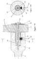
- the articulation (3) comprises a device for locking and unlocking the rotation.
- a rotation blocking device is shown in Figure (10).
- Radial notches (28) are arranged at the bottom of the cylinder (14).
- a cylindrical housing (29) with vertical axis is hollowed out in the lower part of the bulge (22).
- the housing (29) communicates with the orifice (23).
- a helical compression spring (30) surmounted by the part (31).
- the part (31) can slide in the housing (29) upwards under the action of the spring (30) and down under the action of the pull tab (32).
- the part (31) has in its part upper a cleat (33), which cleat is, under the effect of the spring (30), embedded in one of the notches (28).
- the articulation (3) further comprises a stop device limiting the amplitude of the rotation.
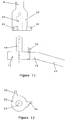
- FIG. 11 represents the said stop device, in exploded top view.
- the pin (36) is fixed in the hole (21) of the arm (2).
- On the bulge (22) are arranged two pins (34) and (35).
- the pins (34) and (35) serve as stops for the displacements of the pin (36) and thereby limit the amplitude of the rotation of the arm (2).
- the lug (35) determines the limit position of the arm (2) in the "awake” position.
- the lug (34) determines the limit position of the arm (2) in the "sleep” position.
- the FIG. 12 represents the bulge (22) of the bar (6), as well as the stops (34) and (35), in external lateral view.
- the articulation device (3) can also be produced by means of an articulation with patella.
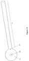
- Figure 13 shows the sliding and rotating tube (4).
- the tube (4) can slide the along the rod (13) and turn around the rod (13).
- a blocking and release of rotation and translation allows the tube (4) to be fixed in the position chosen.
- the tube (4) has a threaded hole (37) into which is screwed the blocking (38). In the locked position, the screw (38) secures the rod (13) and the tube (4).
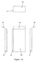
- Figure 14 shows the support surface (5).
- the flange (40) In the “sleep” position, the flange (40) is anterior: it serves as a forehead support, it prevents the passenger's head from sliding towards the front.
- the rim (41) In the “sleep” position, the rim (41) is lower: it prevents the head from passenger to slide down.
- the central surface (39) constitutes the main support.
- the surface (39) is lateral to the passenger.
- the surface support (5) is integral with the tube (4).
- the tube (4) can slide by translation along of the rod (13) of the arm (2), which makes it possible to adjust the distance in the “sleep” position between the bearing surface (5) and the fixing device (1).
- the tube (4) can rotate by rotation around the rod (13) of the arm (2), which makes it possible to adjust, in position "Sleep” means the inclination of the surface (39) and therefore of the surface (5). This possibility for adjusting the inclination of the surface (5) is characteristic of the invention.
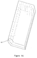
- FIG. 15 shows a perspective view of the bearing surface (5) and tube (4).
- the bearing surface (5) is covered with padding (42).
- the FIG. 16 represents a perspective view of the bearing surface (5) and the padding (42).
- the tube (4) can rotate around the arm (2), which allows the passenger to adjust the value of the angle C.
- the angle C is equal to zero.
- the angle C is adjustable from 0 to 90 degrees, which allows a better adaptation of the temple support to the position of the head of the sleeping passenger.
Landscapes
- Engineering & Computer Science (AREA)
- Aviation & Aerospace Engineering (AREA)
- Transportation (AREA)
- Mechanical Engineering (AREA)
- Chair Legs, Seat Parts, And Backrests (AREA)
Priority Applications (1)
| Application Number | Priority Date | Filing Date | Title |
|---|---|---|---|
| EP99450029A EP1106427A1 (de) | 1999-12-06 | 1999-12-06 | Verstellbare Schlafstütze für Beifahrersitz |
Applications Claiming Priority (1)
| Application Number | Priority Date | Filing Date | Title |
|---|---|---|---|
| EP99450029A EP1106427A1 (de) | 1999-12-06 | 1999-12-06 | Verstellbare Schlafstütze für Beifahrersitz |
Publications (1)
| Publication Number | Publication Date |
|---|---|
| EP1106427A1 true EP1106427A1 (de) | 2001-06-13 |
Family
ID=8242408
Family Applications (1)
| Application Number | Title | Priority Date | Filing Date |
|---|---|---|---|
| EP99450029A Withdrawn EP1106427A1 (de) | 1999-12-06 | 1999-12-06 | Verstellbare Schlafstütze für Beifahrersitz |
Country Status (1)
| Country | Link |
|---|---|
| EP (1) | EP1106427A1 (de) |
Cited By (5)
| Publication number | Priority date | Publication date | Assignee | Title |
|---|---|---|---|---|
| FR2836099A1 (fr) * | 2002-02-15 | 2003-08-22 | Bernard Morel | Repose tete lateral reglable pour enfant |
| GB2415616A (en) * | 2004-06-29 | 2006-01-04 | Ford Global Tech Llc | Vehicle seat assembly including a backrest mounted pivotal headrest for support of the side of a head of an occupant of the assembly |
| WO2006000203A3 (de) * | 2004-06-25 | 2006-05-11 | Grammer Ag | Kopfstütze für einen fahrgastsitz |
| EP1694818A4 (de) * | 2003-12-15 | 2011-09-14 | Be Aerospace Inc | Fahrzeugbeifahrersitz mit einstellbarer kopfstütze |
| CN113557168A (zh) * | 2019-01-15 | 2021-10-26 | A·伊尔凯尔 | 角度机构乘客座椅枕 |
Citations (15)
| Publication number | Priority date | Publication date | Assignee | Title |
|---|---|---|---|---|
| DE3039934A1 (de) | 1980-10-23 | 1982-05-06 | Audi Nsu Auto Union Ag, 7107 Neckarsulm | Kopfstuetze fuer den sitz eines kraftfahrzeuges |
| JPS57158128A (en) | 1981-03-26 | 1982-09-29 | Nissan Motor Co Ltd | Headrest for car |
| US4971393A (en) | 1988-11-27 | 1990-11-20 | Ralph Stas | Sitting furniture, especially for automobile seats |
| EP0470051A1 (de) | 1990-07-30 | 1992-02-05 | Aviointeriors S.R.L. | Vertikal drehbare Kopfstütze für einen Sessel |
| FR2689825A1 (fr) | 1992-04-13 | 1993-10-15 | Peugeot | Appui-tête pour siège de véhicule automobile. |
| US5531505A (en) | 1994-02-25 | 1996-07-02 | Tri-Con Industries, Ltd. | Head restraint for passenger vehicles |
| GB2302268A (en) | 1995-06-14 | 1997-01-15 | Autoliv Dev | Head rest with lateral restraint |
| EP0780072A1 (de) | 1995-12-18 | 1997-06-25 | Yang-Ting Liu | Einstellbare Kopfstütze |
| FR2752548A1 (fr) | 1996-08-20 | 1998-02-27 | Peugeot | Dispositif formant appui-tete pour siege de vehicule automobile |
| WO1998013228A1 (en) | 1996-09-24 | 1998-04-02 | Autoliv Development Ab | Improvements in or relating to a head-rest |
| WO1998032629A1 (en) | 1997-01-23 | 1998-07-30 | Hoover Universal, Inc. | Vehicle seat assembly |
| FR2759559A1 (fr) | 1997-02-17 | 1998-08-21 | Nicolas Jean Charles Rhein | Appui-tete lateral amovible, universel et retractable pour fauteuil ou siege |
| FR2768093A1 (fr) | 1997-09-05 | 1999-03-12 | Gilbert Leon Maurice Calvayrac | Mecanisme articule assurant le maintien lateral de la tete d'un passager de vehicule de transport |
| EP0921032A2 (de) | 1997-12-06 | 1999-06-09 | Volkswagen Aktiengesellschaft | Kopfstütze für einen Sitz, insbesondere für einen Kraftfahrzeugsitz |
| FR2779394A1 (fr) * | 1998-06-03 | 1999-12-10 | Luc Raymond Marie Morin | Appuie-tempe escamotable, a deux positions: eveil et sommeil, pour siege de passager |
-
1999
- 1999-12-06 EP EP99450029A patent/EP1106427A1/de not_active Withdrawn
Patent Citations (15)
| Publication number | Priority date | Publication date | Assignee | Title |
|---|---|---|---|---|
| DE3039934A1 (de) | 1980-10-23 | 1982-05-06 | Audi Nsu Auto Union Ag, 7107 Neckarsulm | Kopfstuetze fuer den sitz eines kraftfahrzeuges |
| JPS57158128A (en) | 1981-03-26 | 1982-09-29 | Nissan Motor Co Ltd | Headrest for car |
| US4971393A (en) | 1988-11-27 | 1990-11-20 | Ralph Stas | Sitting furniture, especially for automobile seats |
| EP0470051A1 (de) | 1990-07-30 | 1992-02-05 | Aviointeriors S.R.L. | Vertikal drehbare Kopfstütze für einen Sessel |
| FR2689825A1 (fr) | 1992-04-13 | 1993-10-15 | Peugeot | Appui-tête pour siège de véhicule automobile. |
| US5531505A (en) | 1994-02-25 | 1996-07-02 | Tri-Con Industries, Ltd. | Head restraint for passenger vehicles |
| GB2302268A (en) | 1995-06-14 | 1997-01-15 | Autoliv Dev | Head rest with lateral restraint |
| EP0780072A1 (de) | 1995-12-18 | 1997-06-25 | Yang-Ting Liu | Einstellbare Kopfstütze |
| FR2752548A1 (fr) | 1996-08-20 | 1998-02-27 | Peugeot | Dispositif formant appui-tete pour siege de vehicule automobile |
| WO1998013228A1 (en) | 1996-09-24 | 1998-04-02 | Autoliv Development Ab | Improvements in or relating to a head-rest |
| WO1998032629A1 (en) | 1997-01-23 | 1998-07-30 | Hoover Universal, Inc. | Vehicle seat assembly |
| FR2759559A1 (fr) | 1997-02-17 | 1998-08-21 | Nicolas Jean Charles Rhein | Appui-tete lateral amovible, universel et retractable pour fauteuil ou siege |
| FR2768093A1 (fr) | 1997-09-05 | 1999-03-12 | Gilbert Leon Maurice Calvayrac | Mecanisme articule assurant le maintien lateral de la tete d'un passager de vehicule de transport |
| EP0921032A2 (de) | 1997-12-06 | 1999-06-09 | Volkswagen Aktiengesellschaft | Kopfstütze für einen Sitz, insbesondere für einen Kraftfahrzeugsitz |
| FR2779394A1 (fr) * | 1998-06-03 | 1999-12-10 | Luc Raymond Marie Morin | Appuie-tempe escamotable, a deux positions: eveil et sommeil, pour siege de passager |
Non-Patent Citations (1)
| Title |
|---|
| PATENT ABSTRACTS OF JAPAN vol. 006, no. 267 (M - 182) 25 December 1982 (1982-12-25) * |
Cited By (6)
| Publication number | Priority date | Publication date | Assignee | Title |
|---|---|---|---|---|
| FR2836099A1 (fr) * | 2002-02-15 | 2003-08-22 | Bernard Morel | Repose tete lateral reglable pour enfant |
| EP1694818A4 (de) * | 2003-12-15 | 2011-09-14 | Be Aerospace Inc | Fahrzeugbeifahrersitz mit einstellbarer kopfstütze |
| WO2006000203A3 (de) * | 2004-06-25 | 2006-05-11 | Grammer Ag | Kopfstütze für einen fahrgastsitz |
| US8007045B2 (en) | 2004-06-25 | 2011-08-30 | Grammer Ag | Headrest for a vehicle seat |
| GB2415616A (en) * | 2004-06-29 | 2006-01-04 | Ford Global Tech Llc | Vehicle seat assembly including a backrest mounted pivotal headrest for support of the side of a head of an occupant of the assembly |
| CN113557168A (zh) * | 2019-01-15 | 2021-10-26 | A·伊尔凯尔 | 角度机构乘客座椅枕 |
Similar Documents
| Publication | Publication Date | Title |
|---|---|---|
| EP0174884B1 (de) | Verstellbare Kopfstütze für Kraftwagensitze oder ähnliches | |
| EP0626292B1 (de) | Fahrzeugsitz mit zurückklappbarem Bildschirm in der Armlehne | |
| FR2751926A1 (fr) | Siege de vehicule comportant un appui-tete, et appui-tete pour siege de vehicule | |
| FR2693157A1 (fr) | Perfectionnements aux dispositifs pour bloquer les composants réglables en position des sièges de véhicules lors des chocs. | |
| FR2616307A1 (fr) | Agencement de controle d'inclinaison pour sieges de bureau | |
| WO2002008013A1 (fr) | Dispositif de securite pour enfant adaptable sur un vehicule | |
| EP1142753B1 (de) | Kopfstütze, insbesondere für Kraftfahrzeugsitze | |
| FR2782038A1 (fr) | Appui-tete | |
| WO2003068556A1 (fr) | Repose-tete lateral reglable | |
| FR2665399A1 (fr) | Dispositif de siege pour passager enfant, integre au composant d'un siege principal de vehicule automobile. | |
| FR2481091A1 (fr) | Dispositif de montage pour siege du type fauteuil | |
| FR2779394A1 (fr) | Appuie-tempe escamotable, a deux positions: eveil et sommeil, pour siege de passager | |
| FR2740405A1 (fr) | Siege auxiliaire | |
| FR2817811A1 (fr) | Siege de vehicule transformable | |
| FR3049577B1 (fr) | Siege convertible en couchage elargi | |
| FR2735096A1 (fr) | Siege orientable de securite pour un vehicule tel qu'un aeronef. | |
| FR2899160A1 (fr) | Siege arriere reglable de vehicule automobile | |
| FR2806677A1 (fr) | Unite de reglage pour appui-tete | |
| FR2696387A1 (fr) | Accoudoir de siège à inclinaisons multiples pour siège de véhicule. | |
| FR2812594A1 (fr) | Siege de vehicule comportant un coussin d'appui lateral | |
| EP0688521B1 (de) | Sitzmöbel mit zahlreichen Einstellmöglichkeiten | |
| FR2847211A1 (fr) | Siege de vehicule automobile | |
| FR2797420A1 (fr) | Siege inclinable pour enfants a blocage anti-choc | |
| FR2855114A1 (fr) | Accoudoir arriere multifonctions pour vehicule automobile | |
| FR3036365A1 (fr) | Selle a dossier reglable longitudinalement et en hauteur pour vehicule motorise etroit |
Legal Events
| Date | Code | Title | Description |
|---|---|---|---|
| PUAI | Public reference made under article 153(3) epc to a published international application that has entered the european phase |
Free format text: ORIGINAL CODE: 0009012 |
|
| AK | Designated contracting states |
Kind code of ref document: A1 Designated state(s): AT BE CH CY DE DK ES FI FR GB GR IE IT LI LU MC NL PT SE |
|
| AX | Request for extension of the european patent |
Free format text: AL;LT;LV;MK;RO;SI |
|
| AKX | Designation fees paid | ||
| REG | Reference to a national code |
Ref country code: DE Ref legal event code: 8566 |
|
| STAA | Information on the status of an ep patent application or granted ep patent |
Free format text: STATUS: THE APPLICATION IS DEEMED TO BE WITHDRAWN |
|
| 18D | Application deemed to be withdrawn |
Effective date: 20011214 |