EP1106761A1 - Sicherheitsschloss für Türe - Google Patents
Sicherheitsschloss für Türe Download PDFInfo
- Publication number
- EP1106761A1 EP1106761A1 EP99500231A EP99500231A EP1106761A1 EP 1106761 A1 EP1106761 A1 EP 1106761A1 EP 99500231 A EP99500231 A EP 99500231A EP 99500231 A EP99500231 A EP 99500231A EP 1106761 A1 EP1106761 A1 EP 1106761A1
- Authority
- EP
- European Patent Office
- Prior art keywords
- sliding bar
- door
- ratchet
- ratchets
- doors
- Prior art date
- Legal status (The legal status is an assumption and is not a legal conclusion. Google has not performed a legal analysis and makes no representation as to the accuracy of the status listed.)
- Granted
Links
- 238000004873 anchoring Methods 0.000 claims description 27
- 230000005484 gravity Effects 0.000 claims description 6
- 230000000284 resting effect Effects 0.000 claims description 5
- 230000009471 action Effects 0.000 claims description 4
- 230000008901 benefit Effects 0.000 description 2
- 230000000295 complement effect Effects 0.000 description 2
- 230000008878 coupling Effects 0.000 description 1
- 238000010168 coupling process Methods 0.000 description 1
- 238000005859 coupling reaction Methods 0.000 description 1
- 230000006870 function Effects 0.000 description 1
- 239000000463 material Substances 0.000 description 1
- 230000007246 mechanism Effects 0.000 description 1
- 239000002184 metal Substances 0.000 description 1
- 230000002787 reinforcement Effects 0.000 description 1
- 239000007787 solid Substances 0.000 description 1
Images



Classifications
-
- E—FIXED CONSTRUCTIONS
- E05—LOCKS; KEYS; WINDOW OR DOOR FITTINGS; SAFES
- E05B—LOCKS; ACCESSORIES THEREFOR; HANDCUFFS
- E05B63/00—Locks or fastenings with special structural characteristics
- E05B63/18—Locks or fastenings with special structural characteristics with arrangements independent of the locking mechanism for retaining the bolt or latch in the retracted position
- E05B63/20—Locks or fastenings with special structural characteristics with arrangements independent of the locking mechanism for retaining the bolt or latch in the retracted position released automatically when the wing is closed
-
- E—FIXED CONSTRUCTIONS
- E05—LOCKS; KEYS; WINDOW OR DOOR FITTINGS; SAFES
- E05C—BOLTS OR FASTENING DEVICES FOR WINGS, SPECIALLY FOR DOORS OR WINDOWS
- E05C9/00—Arrangements of simultaneously actuated bolts or other securing devices at well-separated positions on the same wing
- E05C9/18—Details of fastening means or of fixed retaining means for the ends of bars
- E05C9/1825—Fastening means
- E05C9/1875—Fastening means performing pivoting movements
-
- E—FIXED CONSTRUCTIONS
- E05—LOCKS; KEYS; WINDOW OR DOOR FITTINGS; SAFES
- E05C—BOLTS OR FASTENING DEVICES FOR WINGS, SPECIALLY FOR DOORS OR WINDOWS
- E05C9/00—Arrangements of simultaneously actuated bolts or other securing devices at well-separated positions on the same wing
- E05C9/18—Details of fastening means or of fixed retaining means for the ends of bars
- E05C9/1825—Fastening means
- E05C9/1875—Fastening means performing pivoting movements
- E05C9/1883—Fastening means performing pivoting movements pivotally mounted on the actuation bar
Definitions
- the present invention relates to a safety lock, applicable to any type of door, window, gate or similar swiveling elements, particularly applicable to doors, so that this lock serves to immobilize the door within its frame in a safe, inviolable manner, while occupying a minimum space inside it so that large empty spaces are not required inside the door, which would weaken it precisely at the places where it is attached to the frame.
- the description being means to solve the aforementioned problems by providing a lock which requires a minimum space inside the door, consisting of few elements, very simple to use yet very effective and with no unpleasant aesthetic results.
- the lock is meant to be housed within the door along the edge opposite the hinges, and is provided with a number of ratchets for anchoring to the frame.
- the safety lock is actuated vertically, in other words, in passing from an open to a locked position and vice versa its moving parts move in a vertical direction.
- the lock can be adapted to fit any door and is actuated by conventional means, such as any standard lock or by handles, cams, toothed gears or even electro-mechanical means so that it may be opened or closed at a distance.
- the safety lock for doors comprises a mortise with a number of ratchets housed in it, which ratchets are the anchoring elements of the lock.
- the ratchets will be inserted in the mortise on one end by a shaft which will allow them to balance or move vertically about this shaft.
- each ratchet When locked the ratchets are in a horizontal position, extending outside the mortise through windows made in the latter, one per ratchet, within which each ratchet can move from the locked to the open position as it moves vertically with respect to its axis.
- a sliding bar which moves only vertically as its shape makes it fit perfectly inside the mortising, preventing it from moving in any other direction.
- This sliding bar comprises a U-shaped profile with rectangular windows made in its core, one for each ratchet.
- the ratchet rests horizontally on the lower edge of the mortise window, and on it in turn due to gravity rests the upper edge of the corresponding sliding bar window within a half-rule groove made in the upper part of the ratchet.
- an inverted T-shaped notch in which an anchoring element is inserted which allows vertical movement of the sliding bar, so that when the bar reaches the end of its upwards path this anchoring element inserts in the wide part of the notch driven by an elastic element such as a spring, thus preventing the bar from sliding downwards.
- the front end of the anchoring element is beveled, as well as the outer face of the frame to which the door is locked, these bevel matching so that when the door is closed they touch and slide against each other, making the anchoring element recede and overcome the resistance of the spring until the anchoring element is released from the notch and frees the sliding bar to move downwards by action of gravity.
- the sliding bar In its downwards motion the sliding bar ceases to support the ratchets and eventually touches with the top edge of each of its windows a sloping face of the ratchets, moving them away from their resting position in the open unlocked situation until they are swiveling on the shaft due to their weight.
- the ratchets thus move downwards through the mortise window and return to the locked position.
- This safety lock can be made from any metal or combination thereof.
- Figure 1 shows a perspective view of the door, open, where one can see the lock placed along the front edge, incorporating a number of ratchets. Also shown in this figure is a conventional lock as a standard actuation element.
- Figure 2 shows a perspective view of one of the ratchets of the safety lock, once the door lock is coupled to the door, representing the ratchet in the open position and in a dotted line in a closed position, also showing the sliding bar within the mortise.
- Figure 3 shows a perspective view similar to that of figure 2 of the notch made in the sliding bar and the anchoring element inserted in it when the lock is in the open position.
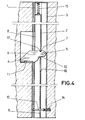
- Figure 4 shows a sectional view of the safety lock in the closed position.
- Figure 5 shows a sectional view of the safety lock similar to figure 4 in the open position.
- the safety lock for doors comprises a mortise, in this preferred embodiment made by coupling profiles (1) and (3).
- This mortise is provided with a window (6) for each ratchet on the outer side of the lock, thus allowing each ratchet (4) to extend beyond the mortise and be coupled within an anchoring orifice made for this purpose in the frame of the door, and to move vertically to pass from the open to locked positions and vice versa.
- Each ratchet (4) is connected jointedly to the mortise by a shaft (5).
- a sliding bar (2) which will house ratchets (4) and which consists of a U-shaped profile with a rectangular window in its core for each ratchet.
- sliding bar (2) The inner face of sliding bar (2) is provided with an inverted T-shaped notch (9). in which an anchoring element (10) is inserted, allowing bar (2) to slide along its lateral narrowing. This anchoring element (10) is constantly acted on by a spring (14) towards the outside of the door.
- ratchets (4) are horizontal and extend out of window (8), resting on the frame anchoring orifice, and the upper edge (17) of the windows on sliding bar (2) rest on ratchet (4) on the half-rule groove (7), whose function will be explained below.
- Anchoring element (10) is at the topmost position of notch (9) as shown in figure 4.
- Each ratchet (4) moves through the corresponding window (8) until it is hidden away in the position of figure 5, that is, in the vertical open position, at which time the anchoring element (10) is placed opposite the widest part of notch (9) and by action of spring (14) enters it and locks it in place, preventing sliding bar (2) from descending and thus securing ratchets (4) in the open position, supporting them by contact of the lower edge (16) on the rounded recess (12).
- anchoring element (10) is now visible outside the door so that when the latter is closed the bevel meets the outer face of the frame which is purposefully also beveled, so that the closing motion is transmitted to the anchoring clement (10) in an inwards direction, overcoming the resistance of spring (14). Said element (10) leaves its original position and allows sliding bar (2) to descend under its own weight.
- sliding bar (2) In its downwards motion sliding bar (2) ceases to support ratchets (4) and eventually the upper edge (17) of each window bears against slope (6) of ratchets (4) making each of these move away from its rest position and pivot about shaft (5), and thus to fall under gravity to the locked position inserting themselves in the anchoring orifice provided in the frame, resting on it with the aid of notch (11).
- each ratchet (4) has its center of gravity displaced from its resting point, shaft (5), which facilitates their swiveling to the closed locked position.
- the invention provides a half-rule groove (7) so that in the close position sliding bar (2) rests inside this groove (7) on each ratchet, as shown in figure 4.
- the invention provides a further advantage as it allows to leave the door open without risk of it shutting involuntarily due to an air current or similar reason, and then being unable to open it if the key were not available.
Landscapes
- Engineering & Computer Science (AREA)
- Mechanical Engineering (AREA)
- Structural Engineering (AREA)
- Gates (AREA)
- Lock And Its Accessories (AREA)
- Securing Of Glass Panes Or The Like (AREA)
- Wing Frames And Configurations (AREA)
Priority Applications (3)
| Application Number | Priority Date | Filing Date | Title |
|---|---|---|---|
| DE69939384T DE69939384D1 (de) | 1999-12-02 | 1999-12-02 | Sicherheitsschloss für Türe |
| EP99500231A EP1106761B1 (de) | 1999-12-02 | 1999-12-02 | Sicherheitsschloss für Türe |
| AT99500231T ATE405719T1 (de) | 1999-12-02 | 1999-12-02 | Sicherheitsschloss für türe |
Applications Claiming Priority (1)
| Application Number | Priority Date | Filing Date | Title |
|---|---|---|---|
| EP99500231A EP1106761B1 (de) | 1999-12-02 | 1999-12-02 | Sicherheitsschloss für Türe |
Publications (2)
| Publication Number | Publication Date |
|---|---|
| EP1106761A1 true EP1106761A1 (de) | 2001-06-13 |
| EP1106761B1 EP1106761B1 (de) | 2008-08-20 |
Family
ID=8242537
Family Applications (1)
| Application Number | Title | Priority Date | Filing Date |
|---|---|---|---|
| EP99500231A Expired - Lifetime EP1106761B1 (de) | 1999-12-02 | 1999-12-02 | Sicherheitsschloss für Türe |
Country Status (3)
| Country | Link |
|---|---|
| EP (1) | EP1106761B1 (de) |
| AT (1) | ATE405719T1 (de) |
| DE (1) | DE69939384D1 (de) |
Cited By (15)
| Publication number | Priority date | Publication date | Assignee | Title |
|---|---|---|---|---|
| EP1375796A3 (de) * | 2002-06-28 | 2006-10-11 | Solarlux Aluminium Systeme Gmbh | Tür- oder Fensterflügelanordnung |
| EP1965008A1 (de) | 2007-03-02 | 2008-09-03 | Metalux | Schliessvorrichtung und Flügel mit einer solchen Vorrichtung |
| US7526933B2 (en) | 2006-10-18 | 2009-05-05 | Master Lock Company Llc | Multipoint door lock |
| WO2010071886A1 (en) * | 2008-12-19 | 2010-06-24 | Amesbury Group, Inc. | High security lock for door |
| US9637957B2 (en) | 2012-11-06 | 2017-05-02 | Amesbury Group, Inc. | Automatically-extending remote door lock bolts |
| US9765550B2 (en) | 2012-08-31 | 2017-09-19 | Amesbury Group, Inc. | Passive door lock mechanisms |
| US9790716B2 (en) | 2014-10-16 | 2017-10-17 | Amesbury Group, Inc. | Opposed hook sliding door lock |
| US9885200B2 (en) | 2012-06-18 | 2018-02-06 | Amesbury Group, Inc. | Handle-actuated sliding door lock actuation assemblies |
| US10662675B2 (en) | 2017-04-18 | 2020-05-26 | Amesbury Group, Inc. | Modular electronic deadbolt systems |
| US10808424B2 (en) | 2017-05-01 | 2020-10-20 | Amesbury Group, Inc. | Modular multi-point lock |
| US10968661B2 (en) | 2016-08-17 | 2021-04-06 | Amesbury Group, Inc. | Locking system having an electronic deadbolt |
| US11066850B2 (en) | 2017-07-25 | 2021-07-20 | Amesbury Group, Inc | Access handle for sliding doors |
| US11441333B2 (en) | 2018-03-12 | 2022-09-13 | Amesbury Group, Inc. | Electronic deadbolt systems |
| US11661771B2 (en) | 2018-11-13 | 2023-05-30 | Amesbury Group, Inc. | Electronic drive for door locks |
| US11834866B2 (en) | 2018-11-06 | 2023-12-05 | Amesbury Group, Inc. | Flexible coupling for electronic deadbolt systems |
Families Citing this family (2)
| Publication number | Priority date | Publication date | Assignee | Title |
|---|---|---|---|---|
| US8939474B2 (en) | 2011-06-03 | 2015-01-27 | Amesbury Group, Inc. | Lock with sliding locking elements |
| US9428937B2 (en) | 2011-07-22 | 2016-08-30 | Amesbury Group, Inc. | Multi-point lock having sequentially-actuated locking elements |
Citations (7)
| Publication number | Priority date | Publication date | Assignee | Title |
|---|---|---|---|---|
| US4050272A (en) * | 1975-05-20 | 1977-09-27 | K.K. Tokai Rika Denki Seisakusho | Lock assembly |
| FR2381883A1 (fr) * | 1977-02-24 | 1978-09-22 | Chauvat Et Sofranq Reunis Emil | Perfectionnement aux portes anti-effraction et coupe-feu |
| US4303264A (en) * | 1978-08-14 | 1981-12-01 | Yoshida Kogyo K.K. | Window latch |
| FR2493900A1 (fr) * | 1980-11-10 | 1982-05-14 | Siegenia Frank Kg | Dispositif de fermeture pour battants de fenetres, vantaux de portes ou autres elements du meme genre du type a coulisse |
| EP0057829A1 (de) * | 1981-02-07 | 1982-08-18 | Donald Malcolm Fullard | Verschlussvorrichtungen |
| EP0424288A1 (de) * | 1989-10-16 | 1991-04-24 | Marc Bouchard | Türverriegelung und Türrahmen mit solcher Verriegelung |
| GB2265935A (en) * | 1992-04-01 | 1993-10-13 | Cego Ltd | Espagnolette type mechanism. |
-
1999
- 1999-12-02 AT AT99500231T patent/ATE405719T1/de not_active IP Right Cessation
- 1999-12-02 EP EP99500231A patent/EP1106761B1/de not_active Expired - Lifetime
- 1999-12-02 DE DE69939384T patent/DE69939384D1/de not_active Expired - Fee Related
Patent Citations (7)
| Publication number | Priority date | Publication date | Assignee | Title |
|---|---|---|---|---|
| US4050272A (en) * | 1975-05-20 | 1977-09-27 | K.K. Tokai Rika Denki Seisakusho | Lock assembly |
| FR2381883A1 (fr) * | 1977-02-24 | 1978-09-22 | Chauvat Et Sofranq Reunis Emil | Perfectionnement aux portes anti-effraction et coupe-feu |
| US4303264A (en) * | 1978-08-14 | 1981-12-01 | Yoshida Kogyo K.K. | Window latch |
| FR2493900A1 (fr) * | 1980-11-10 | 1982-05-14 | Siegenia Frank Kg | Dispositif de fermeture pour battants de fenetres, vantaux de portes ou autres elements du meme genre du type a coulisse |
| EP0057829A1 (de) * | 1981-02-07 | 1982-08-18 | Donald Malcolm Fullard | Verschlussvorrichtungen |
| EP0424288A1 (de) * | 1989-10-16 | 1991-04-24 | Marc Bouchard | Türverriegelung und Türrahmen mit solcher Verriegelung |
| GB2265935A (en) * | 1992-04-01 | 1993-10-13 | Cego Ltd | Espagnolette type mechanism. |
Cited By (20)
| Publication number | Priority date | Publication date | Assignee | Title |
|---|---|---|---|---|
| EP1375796A3 (de) * | 2002-06-28 | 2006-10-11 | Solarlux Aluminium Systeme Gmbh | Tür- oder Fensterflügelanordnung |
| US7526933B2 (en) | 2006-10-18 | 2009-05-05 | Master Lock Company Llc | Multipoint door lock |
| EP1965008A1 (de) | 2007-03-02 | 2008-09-03 | Metalux | Schliessvorrichtung und Flügel mit einer solchen Vorrichtung |
| FR2913245A1 (fr) * | 2007-03-02 | 2008-09-05 | Metalux Soc Par Actions Simpli | Mecanisme de serrure et ouvrant comportant un tel mecanisme. |
| WO2010071886A1 (en) * | 2008-12-19 | 2010-06-24 | Amesbury Group, Inc. | High security lock for door |
| CN102264992A (zh) * | 2008-12-19 | 2011-11-30 | 埃美斯博瑞集团有限公司 | 用于门的高安全性锁 |
| CN102264992B (zh) * | 2008-12-19 | 2015-01-14 | 埃美斯博瑞集团有限公司 | 用于门的高安全性锁 |
| US9758997B2 (en) | 2008-12-19 | 2017-09-12 | Amesbury Group, Inc. | High security lock for door |
| US9885200B2 (en) | 2012-06-18 | 2018-02-06 | Amesbury Group, Inc. | Handle-actuated sliding door lock actuation assemblies |
| US9765550B2 (en) | 2012-08-31 | 2017-09-19 | Amesbury Group, Inc. | Passive door lock mechanisms |
| US9637957B2 (en) | 2012-11-06 | 2017-05-02 | Amesbury Group, Inc. | Automatically-extending remote door lock bolts |
| US9790716B2 (en) | 2014-10-16 | 2017-10-17 | Amesbury Group, Inc. | Opposed hook sliding door lock |
| US10968661B2 (en) | 2016-08-17 | 2021-04-06 | Amesbury Group, Inc. | Locking system having an electronic deadbolt |
| US10662675B2 (en) | 2017-04-18 | 2020-05-26 | Amesbury Group, Inc. | Modular electronic deadbolt systems |
| US11634931B2 (en) | 2017-04-18 | 2023-04-25 | Amesbury Group, Inc. | Modular electronic deadbolt systems |
| US10808424B2 (en) | 2017-05-01 | 2020-10-20 | Amesbury Group, Inc. | Modular multi-point lock |
| US11066850B2 (en) | 2017-07-25 | 2021-07-20 | Amesbury Group, Inc | Access handle for sliding doors |
| US11441333B2 (en) | 2018-03-12 | 2022-09-13 | Amesbury Group, Inc. | Electronic deadbolt systems |
| US11834866B2 (en) | 2018-11-06 | 2023-12-05 | Amesbury Group, Inc. | Flexible coupling for electronic deadbolt systems |
| US11661771B2 (en) | 2018-11-13 | 2023-05-30 | Amesbury Group, Inc. | Electronic drive for door locks |
Also Published As
| Publication number | Publication date |
|---|---|
| EP1106761B1 (de) | 2008-08-20 |
| ATE405719T1 (de) | 2008-09-15 |
| DE69939384D1 (de) | 2008-10-02 |
Similar Documents
| Publication | Publication Date | Title |
|---|---|---|
| EP1106761B1 (de) | Sicherheitsschloss für Türe | |
| EP1907655B1 (de) | Sicherheitssystem für durchgangssperre | |
| GB2317640A (en) | Door chain security devices | |
| NL7900025A (nl) | Noodbedieningsinrichting. | |
| PL206477B1 (pl) | Wieloczłonowa brama podnoszona lub przesuwno-składana | |
| KR200477585Y1 (ko) | 록킹기능을 갖춘 창호 도어용 핸들장치 | |
| RU2324042C2 (ru) | Блокирующий механизм для двери | |
| CN106068358B (zh) | 在结构失效情况下可打开的门 | |
| PL194844B1 (pl) | Dwuskrzydłowe drzwi, zwłaszcza drzwi przeciwpożarowe | |
| EP2309093B1 (de) | Tür mit abschließbarer Öffnung und einer Sicherungseinrichtung dafür | |
| US4093284A (en) | Door construction | |
| EP3857013B1 (de) | Verriegelungsanordnung für rollladen | |
| US4080908A (en) | Shutter assembly for slot or aperture | |
| GB2276190A (en) | Lock assembly | |
| WO2006094368A1 (en) | Locking mechanism | |
| EP0712984A1 (de) | Verriegelungsvorrichtung für Notausgangstüren | |
| EP3874104B1 (de) | Tür oder fenster und schliesssystem für eine tür oder ein fenster | |
| EP0342164A2 (de) | Verschluss für Rolladen oder dergleichen | |
| EP4471242A1 (de) | Scharnierverriegelungsmechanismus | |
| GB2523429A (en) | Door stop | |
| JPH0543187Y2 (de) | ||
| ITBO980108U1 (it) | Dispositivo a sbloccaggio automatico per la chiusura di ante . | |
| EP0663500B1 (de) | Treibstangenverschluss für Fenster, Türen od.dgl. | |
| KR200357498Y1 (ko) | 이동식 방범창 | |
| ES2265698B1 (es) | Dispositivo de cierre para puertas correderas con cerradura. |
Legal Events
| Date | Code | Title | Description |
|---|---|---|---|
| PUAI | Public reference made under article 153(3) epc to a published international application that has entered the european phase |
Free format text: ORIGINAL CODE: 0009012 |
|
| AK | Designated contracting states |
Kind code of ref document: A1 Designated state(s): AT BE CH CY DE DK ES FI FR GB GR IE IT LI LU MC NL PT SE |
|
| AX | Request for extension of the european patent |
Free format text: AL;LT;LV;MK;RO;SI |
|
| 17P | Request for examination filed |
Effective date: 20011212 |
|
| AKX | Designation fees paid |
Free format text: AT BE CH CY DE DK ES FI FR GB GR IE IT LI LU MC NL PT SE |
|
| 17Q | First examination report despatched |
Effective date: 20050705 |
|
| GRAP | Despatch of communication of intention to grant a patent |
Free format text: ORIGINAL CODE: EPIDOSNIGR1 |
|
| GRAS | Grant fee paid |
Free format text: ORIGINAL CODE: EPIDOSNIGR3 |
|
| GRAA | (expected) grant |
Free format text: ORIGINAL CODE: 0009210 |
|
| AK | Designated contracting states |
Kind code of ref document: B1 Designated state(s): AT BE CH CY DE DK ES FI FR GB GR IE IT LI LU MC NL PT SE |
|
| REG | Reference to a national code |
Ref country code: GB Ref legal event code: FG4D |
|
| REG | Reference to a national code |
Ref country code: CH Ref legal event code: EP |
|
| REG | Reference to a national code |
Ref country code: IE Ref legal event code: FG4D |
|
| REF | Corresponds to: |
Ref document number: 69939384 Country of ref document: DE Date of ref document: 20081002 Kind code of ref document: P |
|
| PG25 | Lapsed in a contracting state [announced via postgrant information from national office to epo] |
Ref country code: NL Free format text: LAPSE BECAUSE OF FAILURE TO SUBMIT A TRANSLATION OF THE DESCRIPTION OR TO PAY THE FEE WITHIN THE PRESCRIBED TIME-LIMIT Effective date: 20080820 Ref country code: ES Free format text: LAPSE BECAUSE OF FAILURE TO SUBMIT A TRANSLATION OF THE DESCRIPTION OR TO PAY THE FEE WITHIN THE PRESCRIBED TIME-LIMIT Effective date: 20081201 |
|
| PG25 | Lapsed in a contracting state [announced via postgrant information from national office to epo] |
Ref country code: FI Free format text: LAPSE BECAUSE OF FAILURE TO SUBMIT A TRANSLATION OF THE DESCRIPTION OR TO PAY THE FEE WITHIN THE PRESCRIBED TIME-LIMIT Effective date: 20080820 Ref country code: AT Free format text: LAPSE BECAUSE OF FAILURE TO SUBMIT A TRANSLATION OF THE DESCRIPTION OR TO PAY THE FEE WITHIN THE PRESCRIBED TIME-LIMIT Effective date: 20080820 |
|
| PG25 | Lapsed in a contracting state [announced via postgrant information from national office to epo] |
Ref country code: BE Free format text: LAPSE BECAUSE OF FAILURE TO SUBMIT A TRANSLATION OF THE DESCRIPTION OR TO PAY THE FEE WITHIN THE PRESCRIBED TIME-LIMIT Effective date: 20080820 |
|
| PG25 | Lapsed in a contracting state [announced via postgrant information from national office to epo] |
Ref country code: DK Free format text: LAPSE BECAUSE OF FAILURE TO SUBMIT A TRANSLATION OF THE DESCRIPTION OR TO PAY THE FEE WITHIN THE PRESCRIBED TIME-LIMIT Effective date: 20080820 |
|
| PG25 | Lapsed in a contracting state [announced via postgrant information from national office to epo] |
Ref country code: PT Free format text: LAPSE BECAUSE OF FAILURE TO SUBMIT A TRANSLATION OF THE DESCRIPTION OR TO PAY THE FEE WITHIN THE PRESCRIBED TIME-LIMIT Effective date: 20090120 |
|
| PLBE | No opposition filed within time limit |
Free format text: ORIGINAL CODE: 0009261 |
|
| STAA | Information on the status of an ep patent application or granted ep patent |
Free format text: STATUS: NO OPPOSITION FILED WITHIN TIME LIMIT |
|
| 26N | No opposition filed |
Effective date: 20090525 |
|
| PG25 | Lapsed in a contracting state [announced via postgrant information from national office to epo] |
Ref country code: MC Free format text: LAPSE BECAUSE OF NON-PAYMENT OF DUE FEES Effective date: 20081231 |
|
| REG | Reference to a national code |
Ref country code: CH Ref legal event code: PL |
|
| GBPC | Gb: european patent ceased through non-payment of renewal fee |
Effective date: 20081202 |
|
| PG25 | Lapsed in a contracting state [announced via postgrant information from national office to epo] |
Ref country code: IT Free format text: LAPSE BECAUSE OF FAILURE TO SUBMIT A TRANSLATION OF THE DESCRIPTION OR TO PAY THE FEE WITHIN THE PRESCRIBED TIME-LIMIT Effective date: 20080820 |
|
| REG | Reference to a national code |
Ref country code: IE Ref legal event code: MM4A |
|
| REG | Reference to a national code |
Ref country code: FR Ref legal event code: ST Effective date: 20090831 |
|
| PG25 | Lapsed in a contracting state [announced via postgrant information from national office to epo] |
Ref country code: LI Free format text: LAPSE BECAUSE OF NON-PAYMENT OF DUE FEES Effective date: 20081231 Ref country code: IE Free format text: LAPSE BECAUSE OF NON-PAYMENT OF DUE FEES Effective date: 20081202 Ref country code: DE Free format text: LAPSE BECAUSE OF NON-PAYMENT OF DUE FEES Effective date: 20090701 Ref country code: CH Free format text: LAPSE BECAUSE OF NON-PAYMENT OF DUE FEES Effective date: 20081231 |
|
| PG25 | Lapsed in a contracting state [announced via postgrant information from national office to epo] |
Ref country code: GB Free format text: LAPSE BECAUSE OF NON-PAYMENT OF DUE FEES Effective date: 20081202 |
|
| PG25 | Lapsed in a contracting state [announced via postgrant information from national office to epo] |
Ref country code: SE Free format text: LAPSE BECAUSE OF FAILURE TO SUBMIT A TRANSLATION OF THE DESCRIPTION OR TO PAY THE FEE WITHIN THE PRESCRIBED TIME-LIMIT Effective date: 20081120 |
|
| PG25 | Lapsed in a contracting state [announced via postgrant information from national office to epo] |
Ref country code: FR Free format text: LAPSE BECAUSE OF NON-PAYMENT OF DUE FEES Effective date: 20081231 |
|
| PG25 | Lapsed in a contracting state [announced via postgrant information from national office to epo] |
Ref country code: LU Free format text: LAPSE BECAUSE OF NON-PAYMENT OF DUE FEES Effective date: 20081202 |
|
| PG25 | Lapsed in a contracting state [announced via postgrant information from national office to epo] |
Ref country code: CY Free format text: LAPSE BECAUSE OF FAILURE TO SUBMIT A TRANSLATION OF THE DESCRIPTION OR TO PAY THE FEE WITHIN THE PRESCRIBED TIME-LIMIT Effective date: 20080820 |
|
| PG25 | Lapsed in a contracting state [announced via postgrant information from national office to epo] |
Ref country code: GR Free format text: LAPSE BECAUSE OF FAILURE TO SUBMIT A TRANSLATION OF THE DESCRIPTION OR TO PAY THE FEE WITHIN THE PRESCRIBED TIME-LIMIT Effective date: 20081121 |