EP1106776A1 - Gurtroller, Betätigungsvorrichtung für einen Rolladen oder Rollo mit einem derartigen Gurtroller und Vefahren zur Einstellung der Federspannung dieses Gurtrollers - Google Patents
Gurtroller, Betätigungsvorrichtung für einen Rolladen oder Rollo mit einem derartigen Gurtroller und Vefahren zur Einstellung der Federspannung dieses Gurtrollers Download PDFInfo
- Publication number
- EP1106776A1 EP1106776A1 EP00420250A EP00420250A EP1106776A1 EP 1106776 A1 EP1106776 A1 EP 1106776A1 EP 00420250 A EP00420250 A EP 00420250A EP 00420250 A EP00420250 A EP 00420250A EP 1106776 A1 EP1106776 A1 EP 1106776A1
- Authority
- EP
- European Patent Office
- Prior art keywords
- sleeve
- pin
- spring
- strap
- reel
- Prior art date
- Legal status (The legal status is an assumption and is not a legal conclusion. Google has not performed a legal analysis and makes no representation as to the accuracy of the status listed.)
- Withdrawn
Links
- 238000000034 method Methods 0.000 title claims description 7
- 238000005304 joining Methods 0.000 claims description 5
- 238000005096 rolling process Methods 0.000 claims description 5
- 230000000149 penetrating effect Effects 0.000 claims description 2
- 210000000056 organ Anatomy 0.000 claims 1
- 230000001105 regulatory effect Effects 0.000 abstract 1
- 241000920340 Pion Species 0.000 description 11
- 210000002105 tongue Anatomy 0.000 description 8
- 230000000694 effects Effects 0.000 description 5
- 238000004519 manufacturing process Methods 0.000 description 5
- 238000006073 displacement reaction Methods 0.000 description 3
- 238000009434 installation Methods 0.000 description 3
- 238000004804 winding Methods 0.000 description 3
- 208000031968 Cadaver Diseases 0.000 description 2
- 230000002093 peripheral effect Effects 0.000 description 2
- 230000004308 accommodation Effects 0.000 description 1
- 230000003416 augmentation Effects 0.000 description 1
- 239000002184 metal Substances 0.000 description 1
- 238000005192 partition Methods 0.000 description 1
- 238000007493 shaping process Methods 0.000 description 1
- 230000007704 transition Effects 0.000 description 1
Images

Classifications
-
- E—FIXED CONSTRUCTIONS
- E06—DOORS, WINDOWS, SHUTTERS, OR ROLLER BLINDS IN GENERAL; LADDERS
- E06B—FIXED OR MOVABLE CLOSURES FOR OPENINGS IN BUILDINGS, VEHICLES, FENCES OR LIKE ENCLOSURES IN GENERAL, e.g. DOORS, WINDOWS, BLINDS, GATES
- E06B9/00—Screening or protective devices for wall or similar openings, with or without operating or securing mechanisms; Closures of similar construction
- E06B9/56—Operating, guiding or securing devices or arrangements for roll-type closures; Spring drums; Tape drums; Counterweighting arrangements therefor
- E06B9/78—Operating, guiding or securing devices or arrangements for roll-type closures; Spring drums; Tape drums; Counterweighting arrangements therefor for direct manual operation, e.g. by tassels, by handles
-
- E—FIXED CONSTRUCTIONS
- E06—DOORS, WINDOWS, SHUTTERS, OR ROLLER BLINDS IN GENERAL; LADDERS
- E06B—FIXED OR MOVABLE CLOSURES FOR OPENINGS IN BUILDINGS, VEHICLES, FENCES OR LIKE ENCLOSURES IN GENERAL, e.g. DOORS, WINDOWS, BLINDS, GATES
- E06B9/00—Screening or protective devices for wall or similar openings, with or without operating or securing mechanisms; Closures of similar construction
- E06B9/56—Operating, guiding or securing devices or arrangements for roll-type closures; Spring drums; Tape drums; Counterweighting arrangements therefor
- E06B9/78—Operating, guiding or securing devices or arrangements for roll-type closures; Spring drums; Tape drums; Counterweighting arrangements therefor for direct manual operation, e.g. by tassels, by handles
- E06B2009/785—Operating, guiding or securing devices or arrangements for roll-type closures; Spring drums; Tape drums; Counterweighting arrangements therefor for direct manual operation, e.g. by tassels, by handles by belts, straps, bands, tapes, cords, tassels
Definitions
- the invention relates to a strap winder, operating mechanism for a shutter, roller blind or the like comprising such a reel and a method for adjusting the spring tension of such a reel.
- the expression strap or the like covers all types of flexible links that may be rolled up and used to operate a roller shutter or blind or an equivalent device.
- a strap, strap or any another flexible link for operating a shutter or blind rolling and, more generally, for any device comprising an apron capable of being selectively wound on a tree for whether or not to block an opening, such as a window or building door.
- a strap winder proximity of such an opening such a reel comprising a spring of which a first end is connected directly or indirectly to the strap, while its other end is connected to a fixed point, this spring being enclosed in a generally cylindrical housing arranged inside of a body or covering, as described in EP-A-0 812 795.
- the box containing the spring is generally fixed on a pin integral with the body or covering, the housing comprising a central sleeve intended to be fitted around the pin cited above.
- the case also includes a peripheral part, most often called “crown", intended to be secured to one end of the strap and capable of rotate around the sleeve and the pin according to the position of the strap and any tensile force exercised by a user on it. In operation, this type of device is generally satisfactory.
- the spring of the reel is armed, in this sense that the spring is tensioned by rotating the crown by relative to the sleeve, the crown then being immobilized by relative to the sleeve by means of a removable cooperating cleat with a lever secured to the sleeve.
- the cleat is removed and the spring exerts on the strap, through the crown, an effort winding.
- the initial voltage or arming value of the spring is therefore an average value set at the factory.
- the invention relates to a winder strap of the aforementioned type which comprises controlled means of selective attachment of the housing sleeve in which is arranged the spring and the pin on which this sleeve is mounted, these means being able to immobilize the rotating sleeve around the counter in a first configuration and to allow the rotation of the sleeve around this pawn in a second configuration.
- the adjustment is greatly facilitated compared to state devices technique because the crown can be held together of the strap while the sleeve is rotated to increase or decrease the spring tension. During the adjustment operations, it is therefore possible for the installer to immediately check the result of this rotation by the grip of the strap which remains integral with the crowned.
- the invention also relates to an operating mechanism a shutter, roller blind or equivalent, which includes a strap winder as previously described.
- Such operating mechanism is easier to install and therefore more economical than known devices, while it allows a precise adjustment of the tension of the strap it includes.
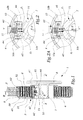
- the reel 1 shown in Figures 1 and 2 is provided for winding a shutter control strap 2 rolling.
- the winder 1 comprises a housing 3 formed by a sleeve 4 and by a peripheral crown 5 and inside which is disposed a flat spring 6.
- the housing 3 is provided to be mounted on a piece 7 piece with a casing 8 of the reel which is partially shown.
- X-X ' the axis of symmetry of pawn 7 which is also a main axis items 3 to 5.
- the sleeve 4 forms two flanges 40 and 41 inside which penetrate the sides 51 and 52 of the crown 5.
- a first end 61 of the spring 6 is made integral with a punctured 42 of the sleeve 4 while its second opposite end 62 is made integral with the crown 5 by any appropriate means.
- the sleeve 4 is immobilized in rotation on pin 7 around the axis XX 'while the crown 5 is able to rotate around of the axis XX ', that is to say of the sleeve 4, as a function of the strap tension 2.
- a lever 43 radially extends the flange 40 on a small width. This lever is able to cooperate with a cleat 53 mounted on the crown 5 to immobilize in rotation elements 4 and 5 before installing the reel. When the reel is positioned on the pin 7, the cleat 53 is removed, so that crown 5 can rotate around the sleeve 4.
- a key 10 is arranged between the outer surface of pin 7, which is grooved, and the inner surface of the sleeve 4.
- the key 10 is mounted on a stirrup 44 radially extending the sleeve 4 in the direction of the axis XX '.
- This stirrup defines, on each of its sides, two oblong slots 45 and 46 inside which are received two axes 10 a and 10 b integral with the key 10 which is therefore capable of sliding in the direction of the arrow F 1 to Figure 2, that is to say radially with respect to the axis XX '.
- a spring 11 is interposed between the sleeve 4 and the key 10 and exerts on it a force F 2 directed towards the axis XX ′. This effort tends to press the key 10 against the pin 7.
- the key 10 is provided with a rib 10 c , the width of which is such that it can penetrate one of the grooves 71 as a function of the position of the sleeve 4 around the pin 7.
- the key 10 thus constitutes a locking clip ordered from the sleeve 4 relative to the pin 7.
- the grooves 71 and the rib 10 c can be inclined, which gives a preferential direction to the rotation movement of the sleeve 4 relative to the pin 7.
- This embodiment has the particular advantage that the key or clip 10 can be pushed back against the force F 2 by an operation consisting in turning the sleeve 4 around the pin 7 in the counterclockwise direction in FIG. 2A .
- This has the effect of driving the rib 10c from the groove 71 in which it is engaged because the inclined surfaces of this rib and of this groove together form ejection ramps from the rib 10c.
- a single rotational movement of the sleeve 4, for example in a direction of arming of the spring 6, has the effect both of releasing the clip 10 and of tensioning the spring 6.
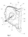
- the reel 101 of this mode of realization is provided for the winding of a strap 102 and includes a housing 103, formed of a sleeve 104 and a crown 105, inside which is disposed a flat spring 106.
- X-X the main axis of the housing 103, that is to say elements 104 to 106.
- a pin 107 in the form of a hollow tube is integral with a shell 108 of the reel 101 provided 181 and 182 mounting brackets against a partition and a brake 183 for strap 102.
- the sleeve 104 is able to be placed around the pin 107 whose external radial surface is generally smooth and whose we denote X-X 'the axis of symmetry.
- a thicker ring 107a is formed on the outer radial surface of pin 107, at close to hull 108.
- a spring 111 is arranged inside the pin 107 while an elastic piece of plastic 110 is intended to close off the end of pin 107 when the sleeve 104 is in place on this one.
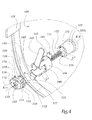
- the geometry of the part 110 is more clearly shown in FIG. 4.
- This part 110 can be considered as a "locking clip" of the housing 103 on the pin 107 because it effectively serves to immobilize the housing 103 on the pin 107.
- the clip 110 comprises a main surface 112 generally in the form of a disc and in which an opening 113 in the form of a cross is formed. From two radial protrusions 114 of the surface 112 extend, parallel to a main axis X 110 -X ' 110 of the clip 110, lugs 115, two in number by protrusions 114. Each lug 115 is provided with a end 116 in the form of a hook directed opposite the tab 115 carried by the same projection 114. In other words, the hooks 116 are directed towards the outside of the volume 117 defined between two adjacent legs 115.
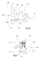
- the sleeve 104 is formed by rolling a sheet of metal 204 shown in Figure 8 and includes three tabs 141, 141 'and 142 intended to be curved radially outward from the sleeve 104 in order to immobilize between them the sides of the crown 105.
- a lever 143 is also provided in the form of a longer length tongue important, this lever being able to cooperate with a cleat formed by the head of a screw inserted in a thread 153 provided in a side 151 of the crown 105.
- the sleeve 104 also defines two clearances 145 and 146 for receiving the legs 115 of the parts 110.
- the sleeve 104 further comprises a tongue 147 intended to allow hooking one end 161 of the spring 106, like the punctured 42 of the first embodiment.
- the sleeve 104 has, over its width in FIG. 8, a groove 104a obtained by striking, this groove being provided to style the rod 107a in the mounted configuration of the device, as shown in Figures 6 and 7.
- this groove being provided to style the rod 107a in the mounted configuration of the device, as shown in Figures 6 and 7.
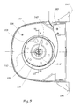
- the sleeve 104 is effectively held in position, by snap-fastening by force, in the axial direction X-X 'of the pin 107.
- the internal surface 171 of the pin 107 forms two depressions 172 and 173 substantially diametrically opposite and extending over a length 1. These depressions 172 and 173 form receptacles for receiving the tongues 118 of the piece 110, and more specifically from their heads 119.
- transition surfaces 172 a and 173 have depressions 172 and 173 and of the cylindrical part 174 are rounded and their shape corresponds to the geometry of the heads 119, which facilitates the passage of these heads from the position of FIG. 6 to that of FIG. 7.
- the heads 119 can rotate freely around the axis XX 'because they are in contact against the surface 174 which is cylindrical. In this position, it is therefore possible to rotate the sleeve 104 around the pin 107, the part 110 being rotated with sleeve 104.
- the invention has been shown with two examples locking members constituted by the key 10 of the first embodiment and by the clip 110 of the second embodiment of achievement. However, it is not limited to these achievements and covers all ordered means of securing selection of the sleeve and the pin of a reel.
Landscapes
- Engineering & Computer Science (AREA)
- Structural Engineering (AREA)
- Architecture (AREA)
- Civil Engineering (AREA)
- Operating, Guiding And Securing Of Roll- Type Closing Members (AREA)
- Storing, Repeated Paying-Out, And Re-Storing Of Elongated Articles (AREA)
Applications Claiming Priority (2)
| Application Number | Priority Date | Filing Date | Title |
|---|---|---|---|
| FR9915635A FR2802193B1 (fr) | 1999-12-10 | 1999-12-10 | Enrouleur de sangle, mecanisme de manoeuvre d'un volet ou store roulant comprenant un tel enrouleur et procede de reglage de la tension du ressort d'un tel enrouleur |
| FR9915635 | 1999-12-10 |
Publications (1)
| Publication Number | Publication Date |
|---|---|
| EP1106776A1 true EP1106776A1 (de) | 2001-06-13 |
Family
ID=9553139
Family Applications (1)
| Application Number | Title | Priority Date | Filing Date |
|---|---|---|---|
| EP00420250A Withdrawn EP1106776A1 (de) | 1999-12-10 | 2000-12-06 | Gurtroller, Betätigungsvorrichtung für einen Rolladen oder Rollo mit einem derartigen Gurtroller und Vefahren zur Einstellung der Federspannung dieses Gurtrollers |
Country Status (4)
| Country | Link |
|---|---|
| EP (1) | EP1106776A1 (de) |
| AU (1) | AU7208100A (de) |
| FR (1) | FR2802193B1 (de) |
| PL (1) | PL344425A1 (de) |
Cited By (3)
| Publication number | Priority date | Publication date | Assignee | Title |
|---|---|---|---|---|
| US7578043B2 (en) | 2002-07-06 | 2009-08-25 | Weatherford/Lamb, Inc. | Coupling tubulars |
| CN105804616A (zh) * | 2015-01-30 | 2016-07-27 | 福建固美金属有限公司 | 一种手动卷帘式窗户的开关方法 |
| CN113482514A (zh) * | 2021-08-26 | 2021-10-08 | 江苏赛迪乐节能科技有限公司 | 内置百叶中空玻璃内用的帘片翻转牵引绳自动涨紧装置 |
Citations (2)
| Publication number | Priority date | Publication date | Assignee | Title |
|---|---|---|---|---|
| EP0096137A1 (de) * | 1982-06-07 | 1983-12-21 | Ets Jean DEPRAT S.A. | Aufwickelvorrichtung in Gehäuse |
| US5938136A (en) * | 1998-10-09 | 1999-08-17 | Miller; James V. | Shutter control strap recoiler |
Family Cites Families (1)
| Publication number | Priority date | Publication date | Assignee | Title |
|---|---|---|---|---|
| DE19623404C2 (de) | 1996-06-12 | 1999-12-30 | Selve Ernst Gmbh Co Kg | Wickelvorrichtung für Gurte, Kordeln o. dgl. |
-
1999
- 1999-12-10 FR FR9915635A patent/FR2802193B1/fr not_active Expired - Fee Related
-
2000
- 2000-12-06 EP EP00420250A patent/EP1106776A1/de not_active Withdrawn
- 2000-12-06 AU AU72081/00A patent/AU7208100A/en not_active Abandoned
- 2000-12-08 PL PL34442500A patent/PL344425A1/xx not_active IP Right Cessation
Patent Citations (2)
| Publication number | Priority date | Publication date | Assignee | Title |
|---|---|---|---|---|
| EP0096137A1 (de) * | 1982-06-07 | 1983-12-21 | Ets Jean DEPRAT S.A. | Aufwickelvorrichtung in Gehäuse |
| US5938136A (en) * | 1998-10-09 | 1999-08-17 | Miller; James V. | Shutter control strap recoiler |
Cited By (5)
| Publication number | Priority date | Publication date | Assignee | Title |
|---|---|---|---|---|
| US7578043B2 (en) | 2002-07-06 | 2009-08-25 | Weatherford/Lamb, Inc. | Coupling tubulars |
| CN105804616A (zh) * | 2015-01-30 | 2016-07-27 | 福建固美金属有限公司 | 一种手动卷帘式窗户的开关方法 |
| CN105804616B (zh) * | 2015-01-30 | 2017-07-14 | 福建固美金属有限公司 | 一种手动卷帘式窗户的开关方法 |
| CN113482514A (zh) * | 2021-08-26 | 2021-10-08 | 江苏赛迪乐节能科技有限公司 | 内置百叶中空玻璃内用的帘片翻转牵引绳自动涨紧装置 |
| CN113482514B (zh) * | 2021-08-26 | 2022-12-27 | 江苏赛迪乐节能科技有限公司 | 内置百叶中空玻璃内用的帘片翻转牵引绳自动涨紧装置 |
Also Published As
| Publication number | Publication date |
|---|---|
| FR2802193B1 (fr) | 2002-06-07 |
| PL344425A1 (en) | 2001-06-18 |
| FR2802193A1 (fr) | 2001-06-15 |
| AU7208100A (en) | 2001-06-14 |
Similar Documents
| Publication | Publication Date | Title |
|---|---|---|
| EP0682492B1 (de) | Automatischer spender für aufwischmaterial und toilettenpapier | |
| EP2894959B1 (de) | Rollschneidkopf mit drähten sowie anordnung aus einem derartigen kopf und einer antriebswelle zur steuerung des kopfes | |
| FR2771620A1 (fr) | Appareil distributeur de papier d'essuyage | |
| CH667191A5 (fr) | Chaussure de ski alpin. | |
| FR2561878A1 (fr) | Dispositif de fermeture, en particulier pour des chaussures de ski a ouverture arriere | |
| CA2212940A1 (fr) | Appareil distributeur de materiau d'essuyage pouvant etre distribues sous forme pliee ou non pliee | |
| FR2560922A1 (fr) | Dispositif pour empecher l'application d'une tension excessive au moteur a ressort d'un store de fenetre | |
| EP0496702A1 (de) | Gleitschutzvorrichtung für Kraftfahrzeugreifen | |
| EP1223843A1 (de) | Spender für aufwischmaterial | |
| EP0255788A1 (de) | Sicherheitsgurtaufroller | |
| FR2683491A1 (fr) | Convertisseur d'energie pour ceinture de securite. | |
| EP1117320B1 (de) | Abwischmaterialspender mit frontaler spulenposition | |
| EP1106776A1 (de) | Gurtroller, Betätigungsvorrichtung für einen Rolladen oder Rollo mit einem derartigen Gurtroller und Vefahren zur Einstellung der Federspannung dieses Gurtrollers | |
| EP2111098A1 (de) | Vorrichtung zur abwicklung eines flexiblen stützdrahtes für weinreben | |
| FR2721377A1 (fr) | Dispositif de connexion à traction pour assembler deux profilés. | |
| EP1983143A1 (de) | Aufrollvorrichtung für eine Tragschnur mit einer Führung für die Schnur | |
| EP0010016B1 (de) | Antriebsmechanismus zur Parallelführung einer Reissschiene auf einem Zeichenbrett | |
| CA2154159C (fr) | Appareil distributeur de materiau d'essuyage et papier toilette a fonctionnement automatique | |
| EP3235968B1 (de) | Anordung von schwenkarmen für rollladen, und entsprechendes montageverfahren | |
| EP2860094A1 (de) | Befestigungsvorrichtung eines abnehmbaren Radelements auf einem Rad, und Verwendung einer solchen Vorrichtung | |
| FR2650732A1 (fr) | Moulinet de peche a bobine debrayable | |
| EP1002931B1 (de) | Seitlicher Führungswagen für Sektionaltore mit vertikaler Öffnung | |
| FR2870670A1 (fr) | Dispositif de devidage d'un tuteur souple pour une plante grimpante | |
| EP0692204A1 (de) | Regelung der Biegsamkeit eines Schischuhes | |
| EP1172517B1 (de) | Rolladen mit Mittel zum Blockieren einer Rolladenwickelwelle |
Legal Events
| Date | Code | Title | Description |
|---|---|---|---|
| PUAI | Public reference made under article 153(3) epc to a published international application that has entered the european phase |
Free format text: ORIGINAL CODE: 0009012 |
|
| AK | Designated contracting states |
Kind code of ref document: A1 Designated state(s): AT BE CH CY DE DK ES FI FR GB GR IE IT LI LU MC NL PT SE TR |
|
| AX | Request for extension of the european patent |
Free format text: AL;LT;LV;MK;RO;SI |
|
| 17P | Request for examination filed |
Effective date: 20011206 |
|
| AKX | Designation fees paid |
Free format text: AT BE CH CY DE DK ES FI FR GB GR IE IT LI LU MC NL PT SE TR |
|
| STAA | Information on the status of an ep patent application or granted ep patent |
Free format text: STATUS: THE APPLICATION IS DEEMED TO BE WITHDRAWN |
|
| 18D | Application deemed to be withdrawn |
Effective date: 20040701 |