EP1106790B1 - Verfahren zur Regelung elktromagnetischer Aktuatoren für die Bedienung von Ein-und Auslassventilen in einer Brennkraftmaschine - Google Patents
Verfahren zur Regelung elktromagnetischer Aktuatoren für die Bedienung von Ein-und Auslassventilen in einer Brennkraftmaschine Download PDFInfo
- Publication number
- EP1106790B1 EP1106790B1 EP00125597A EP00125597A EP1106790B1 EP 1106790 B1 EP1106790 B1 EP 1106790B1 EP 00125597 A EP00125597 A EP 00125597A EP 00125597 A EP00125597 A EP 00125597A EP 1106790 B1 EP1106790 B1 EP 1106790B1
- Authority
- EP
- European Patent Office
- Prior art keywords
- stage
- actual
- force
- calculating
- valve
- Prior art date
- Legal status (The legal status is an assumption and is not a legal conclusion. Google has not performed a legal analysis and makes no representation as to the accuracy of the status listed.)
- Expired - Lifetime
Links
Images


Classifications
-
- F—MECHANICAL ENGINEERING; LIGHTING; HEATING; WEAPONS; BLASTING
- F01—MACHINES OR ENGINES IN GENERAL; ENGINE PLANTS IN GENERAL; STEAM ENGINES
- F01L—CYCLICALLY OPERATING VALVES FOR MACHINES OR ENGINES
- F01L9/00—Valve-gear or valve arrangements actuated non-mechanically
- F01L9/20—Valve-gear or valve arrangements actuated non-mechanically by electric means
- F01L9/21—Valve-gear or valve arrangements actuated non-mechanically by electric means actuated by solenoids
- F01L2009/2105—Valve-gear or valve arrangements actuated non-mechanically by electric means actuated by solenoids comprising two or more coils
- F01L2009/2109—The armature being articulated perpendicularly to the coils axes
-
- F—MECHANICAL ENGINEERING; LIGHTING; HEATING; WEAPONS; BLASTING
- F01—MACHINES OR ENGINES IN GENERAL; ENGINE PLANTS IN GENERAL; STEAM ENGINES
- F01L—CYCLICALLY OPERATING VALVES FOR MACHINES OR ENGINES
- F01L2201/00—Electronic control systems; Apparatus or methods therefor
Definitions
- the present invention relates to a method for the control of electromagnetic actuators for the actuation of intake and exhaust valves in internal combustion engines.
- the corresponding actuators when each valve is opened or closed, the corresponding actuators are supplied with currents and/or voltages of a value such as to ensure that the valve, irrespective of the resistance opposing it, reaches the desired position within a predetermined time interval.
- valves In the first place, the valves are subject to impacts each time that they come into contact with fixed members in the position of maximum opening (lower contact) or in the closed position (upper contact). This is particularly critical, since the valves are subject to an extremely high number of opening and closing cycles and therefore wear very rapidly.
- DE-A-197 59 840 discloses a method for the control of electromagnetic actuators for the actuation of intake and exhaust valves in internal combustion engines as defined in the preamble of claim 1.
- the object of the present invention is to provide a method for the control of electromagnetic actuators that is free from the above-described drawbacks and, in particular, has a reduced sensitivity to disturbances, making it possible to improve the overall efficiency of the drive unit.
- the present invention therefore relates to a method for the control of electromagnetic actuators for the actuation of intake and exhaust valves in internal combustion engines, in which an actuator, connected to a control unit, is coupled to a respective valve and comprises a moving member actuated magnetically, by means of a net force, in order to control the movement of the valve between a closed position and a position of maximum opening and an elastic member adapted to maintain the valve in a rest position, which method comprises the stages of
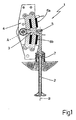
- an electromagnetic actuator 1 controlled by a control system of the present invention is coupled to an intake or exhaust valve 2 of an internal combustion engine and comprises an oscillating arm 3 of ferromagnetic material, having a first end hinged on a fixed support 4 so as to be able to oscillate about a horizontal axis of rotation A perpendicular to a longitudinal axis B of the valve 2, and a second end connected via a hinge 5 to an upper end of the valve 2, an opening electromagnet 6a and a closing electromagnet 6b disposed on opposite sides of the body of the oscillating arm 3 so as to be able to act on command, simultaneously or alternatively, by exerting a net force F on the oscillating arm 3 in order to cause it to rotate about the axis of rotation A and an elastic member 7, adapted to maintain the oscillating arm 3 in a rest position in which it is equidistant from the polar heads of the opening and closing electromagnets 6a and 6b, so as to maintain the valve 2 in an intermediate position
- the opening stroke should be understood as a movement of the valve 2 from the closed position to the position of maximum opening, while the closing stroke should be understood as a full stroke in the opposite direction.
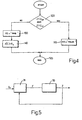
- a control unit 10 comprises a reference generation block 11, a force control block 12, a conversion block 13 and an estimation block 14 and is further interfaced with a guiding and measurement circuit 15.
- the reference generation block 11 receives as input an objective position signal Z T , generated in a known manner by the control unit, and a plurality of parameters indicative of the engine operating conditions (for instance the load L and the number of revolutions RPM).
- the reference generation block 11 also supplies as output a reference position profile Z R and a reference velocity profile V R and supplies them as input to the force control block 12 which also receives a measurement of the actual position Z, supplied by the guiding and measurement circuit 15, and an estimate of the actual velocity V of the valve 2 which is carried out, as described in detail below, by the observation block 14.
- the force control block 12 calculates and supplies as output an objective force value F o indicative of the net force F to be applied to the oscillating arm 3 by means of the electromagnets 6a and 6b in order to minimise the deviations of the actual position Z and of the actual velocity V from the reference position Z R and reference velocity V R profiles respectively.
- the objective force value F o is supplied as input to the conversion block 13 which also receives upper and lower nominal force values F SUP and F INF applied to the oscillating arm 3 by the upper and lower electromagnets 6a and 6b respectively in nominal conditions, and a estimate of disturbing forces ⁇ F.
- the values of the upper and lower nominal forces F SUP and F INF and the estimate of the disturbing forces ⁇ F are supplied by the observation block 14, as will be described in detail below.
- the conversion block 13 supplies as output a pair of upper and lower objective current values I OSUP and I OINF that need to be applied to the upper electromagnet 6a and the lower electromagnet 6b respectively in order to generate the objective force value F o .
- the guiding and measurement circuit 15 receives as input the objective current values I OSUP and I OINF and causes the corresponding upper and lower electromagnets 6a and 6b to be supplied with respective actual currents I SUP and I INF .
- a position sensor 16 of known type adapted to detect the position of the valve 2 or, in an equivalent way, of the oscillating arm 3.
- the position sensor 16 supplies a signal V Z indicative of the actual position Z of the valve 2 to the guiding and measurement circuit 15 which in turn supplies the measurement of the actual position Z and respective measured current values I MSUP and I MINF of the actual currents I SUP and I INF to the control unit 10 and in particular to the observation block 14
- the estimation block 14 calculates and supplies as output an estimate of the actual velocity V, which is supplied to the force control block 12, an estimate of the disturbing forces ⁇ F and the values of the nominal forces F SUP and F INF exerted on the oscillating arm 3 by the upper and lower electromagnets 6a and 6b respectively.
- the estimation block 14 comprises, as shown in Fig, 3, a calculation block 20 which receives as input the measurements of the actual position Z and the measured current values I MSUP and I MINF and supplies as output the values of the nominal forces F SUP and F INF which represent outputs from the estimation block 14.
- the measurement of the actual position Z is also supplied as input to an initialisation block 21 which supplies as output an initialisation signal RS, of logic type, and an initialisation vector X 1 , whose structure will be explained below.
- An observation block 22 receives as input the measurement of the actual position Z, the values of the nominal forces F SUP and F INF and the initialisation vector X 1 .
- An estimate of the state vector X'(t), which represents an output from the observation block 22, is calculated on the basis of these inputs.
- the estimation block 14 further comprises a selector block 23, controlled by the initialisation block 21 by means of the initialisation signal RS.
- the selector block 23 is adapted to connect an input of an extraction block 24 alternatively with the output of the initialisation block 21, when the initialisation signal assumes a first logic value (“TRUE”) or with the output of the observation block 22, when the initialisation signal RS assumes a second logic value (“FALSE").
- the extraction block 24 obtains, from the initialisation vector X 1 or from the estimate of the state vector X'(t), depending on the value assumed by the initialisation signal RS, estimates of the actual velocity V and of the disturbing forces ⁇ F and supplies them as outputs of the estimation block 14.
- the control unit 10 determines the moments of opening and closing of the valve 2. At the same time, it sets the objective position signal Z T to a value representative of the position that the valve 2 should assume.
- the objective position signal Z T is in particular assigned an upper value Z SUP corresponding to the upper contact or a lower value Z INF corresponding to the lower contact, depending on whether the control unit 10 has supplied a command to open or close the valve 2.
- the reference generation block 11 determines the reference position profile Z R and the velocity reference profile V R which respectively represent the position and the velocity which, as a function of time, it is desired to impose on the valve 2 during its displacement between the positions of maximum opening and closure.
- These profiles may for instance be calculated from the objective position signal Z T by means of a two-state non-linear filter, implemented in a known manner by the reference generation block 11, or taken from tables drawn up at the calibration stage.
- the estimation block 14 supplies the values of the upper and lower nominal forces F SUP and F INF , the disturbing forces ⁇ F and the actual velocity V.
- the disturbing forces ⁇ F represent the difference between the objective force value F o and the net force F actually applied to the oscillating arm 3. This difference is due to the variations which, as discussed above, take place with respect to the nominal operating conditions and which have an impact on the movement of the valve 2.
- the calculation block 20 supplies the values of the upper and lower nominal forces F SUP and F INF , as shown in Fig. 3.
- D SUP represents a distance between the polar head of the upper electromagnet 6a and the oscillating arm 3
- ⁇ is a coefficient of proportionality
- I SAT is a saturation current.
- I SUP equal to the saturation current I SAT
- the maximum upper nominal force F SUP that the upper electromagnet 6a is able to exert on the oscillating arm 3 is reached.
- I SUP higher than the saturation current I SAT the upper nominal force F SUP is kept substantially unchanged.
- the coefficient of proportionality ⁇ and the saturation current I SAT depend in a known manner on the distance D SUP and can be obtained by interpolation from respective tables.
- the lower nominal force F INF may be obtained in a completely analogous manner from the equations (1) and (2), in which use should be made of the actual current I INF and a distance D INF between the polar head of the lower electromagnet 6b and the oscillating arm 3 rather than the actual current I SUP and the distance D SUP .
- X(t) and X(t+1) are state vectors of the dynamic system S at the current sampling moment t and at the successive sampling moment t+1;
- U(t) is an input representative of the total nominal force F T given by the sum of the upper and lower nominal forces F SUP and F INF ;
- Y(t) is an output representing the actual position Z;
- A is a transition matrix;
- B is an input matrix and C is an output matrix.
- X 1 , X 2 , X 3 and X 4 are state variables of the dynamic system S corresponding respectively to the actual position Z, the actual velocity V, the disturbing forces ⁇ F and the variations of the disturbing forces ⁇ F, K is an elastic constant, R is a viscous constant, M is an equivalent total mass and ⁇ t is a sampling interval.
- X'(t) and X'(t+1) are estimates of the state vectors X(t) at the moment t and, respectively, X(t+1) at the successive moment t+1
- Y'(t) is an estimate of the output Y(t)
- U'(t) is an input vector of the observer S'.
- the input vector U't is a column vector having the input U(t) as the first member and the output Y(t) as the second member.
- the estimate of the state vector X'(t) supplied by the observer S' coincides with the state vector X(t) of the dynamic system S and, consequently, the elements X' 2 (t) and X' 3 (t) represent estimates of the actual velocity V and of the disturbing forces ⁇ F at the time t respectively.
- the initialisation block 21 carries out an initialisation procedure that will be described below, with reference to Fig. 4.
- a test is carried out to check whether the valve 2 is in a free section of stroke, assessing whether the actual position Z is strictly between the upper contact Z SUP and the lower contact Z INF (block 100). If this condition is satisfied (output YES from the block 100), the initialisation signal RS is assigned the logic value "FALSE" (block 110) and the procedure is concluded (block 120).
- X 1 " and X 2 " are state variables of the reduced dynamic system S" calculated at the moment t and at the successive moment t+1 and corresponding to the actual position Z and the actual velocity V respectively;
- U"(t) is an input representing the net force F and
- Y"(t) is an output of the reduced dynamic system S" represented by the actual position Z.
- the force control block 12 therefore carries out, with respect to the reduced dynamic system S", the function of a feedback controller, shown by 31 in Fig. 5, which uses the net force F as the control variable in order to impose that the controlled variable, i.e. the actual position Z, has a course that is as close as possible to a predetermined course given by the reference position profile Z R .
- the objective force value F o calculated by the force control block 12 and the values of the upper and lower nominal forces F SUP and F INF are used by the conversion block 13 to determine, according to a control procedure known as "switching", that will be explained below with reference to Fig. 6, the objective current values I OSUP and I OINF of the respective currents I SUP and I INF that need to be supplied to the upper and lower electromagnets 6a and 6b.
- switching a control procedure known as "switching”
- an actual force value F E that it is necessary to supply in order to exert on the oscillating arm 3 a net force F of a value equal to the objective force value F o is calculated.
- the implementation of the actual force F E is then controlled. A test is therefore carried out in which the actual force F E and the upper nominal force F SUP are compared (block 210).
- an actuation current value I ON is calculated (block 215) and the upper objective current value I OSUP is set to this actuation value I ON (block 220). If not (output NO from the block 210), an exclusion current value I OFF is calculated (block 225) and the upper objective current value I OSUP is set to this exclusion value I OFF (block 230).
- the actuation value I ON and the exclusion value I OFF are calculated as a function of the distance between the polar heads of the electromagnets 6a and 6b and the oscillating arm 3 as explained below.
- a test is then carried out to check whether the actual force F E is lower than the lower nominal force F INF (block 240). If so (output YES from the block 240), an actuation current value I ON is calculated (block 245) and the lower objective current value I OINF is set to this actuation value I ON (block 250). Otherwise (output NO from the block 240), an exclusion current value I OFF is calculated (block 255) and the lower objective current value I OINF is set to this exclusion value I OFF (block 260).
- the procedure is then terminated (block 270).
- the distance D SUP is shown on the abscissa and the curve of the actuation current values I ON is shown by a continuous line, while the exclusion current values I OFF are shown in dashed lines.
- the actuation current I ON is close to the saturation current I SAT ; as the distance D SUP increases the actuation current I ON firstly moves away from the saturation current I SAT , then decreases until it becomes substantially zero beyond a distance D MAX
- the exclusion current I OFF is maximum when the distance D SUP is zero and gradually decreases until it is cancelled out, without ever exceeding the actuation current I ON .
- the actuation and exclusion current values I ON and I OFF my be taken from tables.
- both the upper and lower electromagnets 6a and 6b can be supplied during a same closing or opening stroke of the valve 2, to enable the net force F exerted on the oscillating arm 3 to have a value equal to the objective force value F o .
- the force control block 12 can generate an objective force value F o such as to exert a braking action on this valve 2.
- This braking action is thus obtained by de-activating the upper electromagnet 6a and supplying the lower electromagnet 6b while the valve 2 is still moving towards the upper contact Z SUP .
- the upper electromagnet 6a is used to brake the valve 2, while the lower electromagnet 6b makes it possible to accelerate the valve 2.
- the stages of supply and de-activation of the electromagnets 6a and 6b in order to accelerate or brake the valve 2 as described above are repeated in sequence several times during each opening and closing stroke, preferably with a frequency of some 20 kHz, so as to minimise the deviations of the actual position Z and the actual velocity V of the valve 2 from the reference position profile Z R and the reference velocity profile V R respectively.
- the use of the estimate of force disturbances ⁇ F makes it possible to impose a robust control and to reduce its sensitivity to unforeseeable variations of the operating conditions, such as those already described and brought about by heat gradients, to different pressure conditions of the gases within the combustion chamber, or caused by wear.
- the estimate of the disturbing forces ⁇ F makes it possible simply to take account of the overall effect of all the disturbances acting on the valve 2. Consequently, it is possible to cause the valves accurately to follow desired position and velocity courses, and to moderate velocity at the end-of-stroke sections, so that the contact between the valves and the fixed members takes place gently. This makes it possible to obtain a so-called "soft touch", avoiding impacts that would substantially reduce the life of the valves and would make the use of electromagnetic actuation systems problematic for mass-produced vehicles.
- the estimate of the actual velocity V which is a key parameter for the efficacy of the control, is carried out by means of the observer S'. In this way, this estimate is extremely accurate and has a very low sensitivity to disturbances.
- the proposed method advantageously makes it possible to reduce current consumption and substantially to improve the overall performance of the drive unit. As a result of the lower current absorption, moreover, there is less risk of damage to the windings of the electromagnets as a result of overheating.
- an actuator 45 cooperates with an intake or exhaust valve 46 and comprises an anchor of ferromagnetic material 47 joined rigidly to a stem 48 of the valve 46 and disposed perpendicular to its longitudinal axis C, a pair of electromagnets 49a and 49b at least partially bounding the stem 48 of the valve 46 and disposed on opposite sides with respect to the anchor 47, so as to be able to act, on command, alternatively or simultaneously, by exerting a net force F on the anchor 47 in order to cause it to move in translation parallel to the longitudinal axis C and an elastic member 50 adapted to maintain the anchor 47 in a rest position in which it is equidistant from the polar heads of the two electromagnets 49a and 49b so as to maintain the valve 46 in an intermediate position between the closed position (upper contact) and the position of maximum opening (lower contact) that the valve 46 assumes when
Landscapes
- Engineering & Computer Science (AREA)
- Mechanical Engineering (AREA)
- General Engineering & Computer Science (AREA)
- Valve Device For Special Equipments (AREA)
- Magnetically Actuated Valves (AREA)
- Output Control And Ontrol Of Special Type Engine (AREA)
Claims (13)
- Verfahren zur Steuerung von elektromagnetischen Betätigungseinrichtungen für die Betätigung von Einlass- und Auslassventilen bei Verbrennungsmotoren, bei denen eine Betätigungseinrichtung (1, 45), die mit einer Steuereinheit (10) verbunden ist, mit einem jeweiligen Ventil (2, 46) gekoppelt ist und ein sich bewegendes Element (3, 47), das magnetisch durch eine Nettokraft (F) betätigt wird, um die Bewegung des Ventils (2, 46) zwischen einer Schließstellung (ZSUP) und einer Stellung maximaler Öffnung (ZINF) zu steuern, und ein elastisches Element (7, 50) umfasst, das dazu bestimmt ist, das Ventil (2, 46) in einer Ruhestellung zu halten, wobei das Verfahren die Schritte umfasst:Feststellen einer Istposition (Z) und einer Istgeschwindigkeit (V) des Ventils (2, 46);Bestimmen einer Referenzpositon (ZR) und einer Referenzgeschwindigkeit (VR) dieses Ventils (2, 46);Schätzen von Störkräften (ΔF), die an dem Ventil (2, 46) wirken,
dadurch gekennzeichnet, dass es die Schritte umfasst:Bestimmen, durch einen Rückkopplungs-Steuerungsvorgang, einer objektiven Kraftgröße (Fo) dieser Nettokraft (F), die auf das sich bewegende ferromagnetische Element (3, 47) auszuüben ist, als Funktion der Referenzposition (ZR), der Istposition (Z), der Referenzgeschwindigkeit (VR) und der Istgeschwindigkeit (V), um die Unterschiede zwischen der Istposition (Z) und der Referenzpositon (ZR) und zwischen der Istgeschwindigkeit (V) und der Referenzgeschwindigkeit (VR) zu minimieren;Berechnen einer Istkraft (FE) als Funktion der objektiven Kraftgröße (Fo) und dieser Störkräfte (ΔF);Implementieren dieser aktuellen Kraftgröße (FE). - Verfahren nach Anspruch 1, dadurch gekennzeichnet, dass der Schritt des Schätzens der Störkräfte die Schritte umfasst:Liefern einer Schätzung (X') eines Zustandes (X) eines dynamischen Systems (S) mittels eines Beobachters (S'), wobei eine erste Zustandsvariable (X3) dieses dynamischen Systems (S) durch diese Störkräfte (ΔF) gebildet wird.
- Verfahren nach Anspruch 2, dadurch gekennzeichnet, dass der Schritt des Liefems dieser Schätzung (X') die Schritte umfasst:Berechnen einer Schätzung (X'(t+1)) in einem sukzessiven Abtastmoment ((t+1)) als Funktion einer Schätzung (X'(t)) in einem sukzessiven Abtastmoment ((t)).
- Verfahren nach Anspruch 3, dadurch gekennzeichnet, dass der Schritt des Berechnens dieser Schätzung (X'(t+1)) in diesem sukzessiven Abtastmoment ((t+1)) den Schritt umfasst:Berechnen dieser Schätzung (X'(t+1)) in einem sukzessiven Abtastmoment ((t+1)) mit der Matrizengleichung:
 wobei A' eine erste Übergangsmatrix ist, B' eine erste Eingabematrix ist und U' ein Eingabevektor des Beobachters (S') ist.
 - Verfahren nach Anspruch 4, dadurch gekennzeichnet, dass der Schritt des Berechnens dieser Schätzung (X'(t+1)) mit der Matrizengleichung den Schritt umfasst:Berechnen dieser ersten Übergangsmatrix A' mit der Matrizengleichung:
 wobei A eine zweite Übergangsmatrix ist, C eine Ausgabematrix des dynamischen Systems (S) ist und L eine Verstärkungsmatrix des Beobachters (S') ist.
 - Verfahren nach einem der vorausgehenden Ansprüche, dadurch gekennzeichnet, dass der Schritt des Berechnens einer Istkraft (FX) den Schritt umfasst:Subtrahieren der Störkräfte (ΔF) von der objektiven Kraftgröße (Fo).
- Verfahren nach einem der vorausgehenden Ansprüche, bei dem die Betätigungseinrichtung (1, 45) weiter umfasst mindestens einen ersten und einen zweiten Elektromagnet (6a, 6b, 49a, 49b), die an gegenüber liegenden Seiten mit Bezug auf das sich bewegende Element (3, 47) angeordnet sind, und bei dem das Ventil (2, 46) einen Öffnungshub durchläuft, wenn es sich aus der Schließstellung (ZSUP) zu der Stellung maximaler Öffnung (ZINF) bewegt, und einen Schließhub durchläuft, wenn es sich aus der Stellung maximaler Öffnung (ZINF) zu der Schließstellung (ZSUP) bewegt, wobei das Verfahren dadurch gekennzeichnet ist, dass der Schritt des Implementierens der Istkraftgröße (FE) den Schritt umfasst:Versorgen sowohl des ersten als auch des zweiten Elektromagneten (6a, 6b, 49a, 49b) mindestens einmal während jedes Öffnungs- und Schließhubs des Ventils (2, 46).
- Verfahren nach Anspruch 7, dadurch gekennzeichnet, dass der Schritt des Versorgens sowohl des ersten als auch des zweiten Elektromagneten (6a, 6b, 49a, 49b) mindestens einmal auf den Schritt folgt:Berechnen, als Funktion der Istposition (Z) und der jeweiligen gemessenen Stromgrößen (IMSUP, IMINF), einer ersten und einer zweiten nominalen Kraftgröße (FSUB, FINF), die durch den ersten bzw. den zweiten Elektromagnet (6a, 6b, 49a, 49b) auf das sich bewegende Element (3, 47) ausgeübt wird.
- Verfahren nach Anspruch 7, dadurch gekennzeichnet, dass der Schritt des Versorgens sowohl des ersten als auch des zweiten Elektromagneten (6a, 6b, 49a, 49b) mindestens einmal den Schritt umfasst:Berechnen mindestens einer ersten und einer zweiten objektiven Stromgröße (IOSUB, IOINF) als Funktion der objektiven Kraftgröße (Fo) undVersorgen des ersten und des zweiten Elektromagneten (6a, 6b, 49a, 49b) mit einem ersten und einem zweiten Strom (ISUB, IINF) die Größen haben, welche gleich der ersten bzw. der zweiten objektiven Stromgröße (IOSUB, IOINF) sind.
- Verfahren nach Anspruch 8, dadurch gekennzeichnet, dass der Schritt des Berechnens mindestens einer ersten und einer zweiten objektiven Stromgröße (IOSUB, IOINF) den Schritt umfasst:Berechnen für sowohl den ersten als auch den zweiten Elektromagneten (6a, 6b, 49a, 49b) mindestens einer Betätigungsstromgröße (ION) und mindestens einer Ausschlussstromgröße (IOFF) (215, 225, 245, 255) als Funktion der jeweiligen Abstände (DSUP, DINF) des sich bewegenden Elements (3, 47) vom ersten Elektromagnet (6a, 49a) und vom zweiten Elektromagnet (6b, 49b).
- Verfahren nach Anspruch 8 und 10, dadurch gekennzeichnet, dass der Schritt des Berechnens mindestens einer ersten und einer zweiten objektiven Stromgröße (IoSUB, IoINF) weiter die Schritte umfasst:Einstellen dieser ersten objektiven Stromgröße (IOSUP) auf diese Betätigungsgröße (ION), wenn die Istkraft (FE) größer als die erste Sollkraft (FSUP) ist,Einstellen dieser ersten objektiven Stromgröße (IOSUP) auf diese Ausschlussgröße (IOFF), wenn die Istkraft (FE) kleiner als die erste Sollkraft (FSUP) ist,Einstellen dieser zweiten objektiven Stromgröße (IOINF) auf diese Betätigungsgröße (ION), wenn die Sollkraft (FE) kleiner als die zweite Sollkraft (FINF) ist,Einstellen dieser zweiten objektiven Stromgröße (IOINF) auf diese Ausschlussgröße (IOFF), wenn die Istkraft (FE) größer als die zweite Sollkraft (FINF) ist.
- Verfahren nach Anspruch 1, dadurch gekennzeichnet, dass der Schritt des Feststellens der Istposition (Z) und der Istgeschwindigkeit (V) den Schritt umfasst:Schätzen der Istgeschwindigkeit (V).
- Verfahren nach Anspruch 5, bei dem eine zweite Zustandsvariable (X2) des dynamischen Systems (S) durch die Istgeschwindigkeit (V) gebildet wird, dadurch gekennzeichnet, dass der Schritt des Schätzens der Istgeschwindigkeit (V) die Schritte umfasst:Liefern einer Schätzung (X') eines Zustandes (X) eines dynamischen Systems (S),Berechnen einer Schätzung (X'(t+1)) in einem sukzessiven Abtastmoment ((t+1)),Berechnen dieser Schätzung (X'(t+1)) in einem sukzessiven Abtastmoment ((t+1)) mit der Matrizengleichung:
 Berechnen der ersten Übergangsmatrix A' mit der Matrizengleichung:
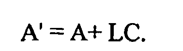
Applications Claiming Priority (2)
| Application Number | Priority Date | Filing Date | Title |
|---|---|---|---|
| ITBO990656 | 1999-11-30 | ||
| IT1999BO000656A IT1311411B1 (it) | 1999-11-30 | 1999-11-30 | Metodo per il controllo di attuatori elettromagnetici perazionamento di valvole di aspirazione e scarico in motori a |
Publications (4)
| Publication Number | Publication Date |
|---|---|
| EP1106790A2 EP1106790A2 (de) | 2001-06-13 |
| EP1106790A8 EP1106790A8 (de) | 2001-11-14 |
| EP1106790A3 EP1106790A3 (de) | 2002-02-13 |
| EP1106790B1 true EP1106790B1 (de) | 2006-02-22 |
Family
ID=11344385
Family Applications (1)
| Application Number | Title | Priority Date | Filing Date |
|---|---|---|---|
| EP00125597A Expired - Lifetime EP1106790B1 (de) | 1999-11-30 | 2000-11-22 | Verfahren zur Regelung elktromagnetischer Aktuatoren für die Bedienung von Ein-und Auslassventilen in einer Brennkraftmaschine |
Country Status (6)
| Country | Link |
|---|---|
| US (1) | US6332436B1 (de) |
| EP (1) | EP1106790B1 (de) |
| BR (1) | BR0006746A (de) |
| DE (1) | DE60026103T2 (de) |
| ES (1) | ES2257255T3 (de) |
| IT (1) | IT1311411B1 (de) |
Families Citing this family (4)
| Publication number | Priority date | Publication date | Assignee | Title |
|---|---|---|---|---|
| IT1311434B1 (it) * | 1999-12-17 | 2002-03-12 | Magneti Marelli Powertain Spa | Metodo per il controllo di attuatori elettromagnetici perl'azionamento di valvole di aspirazione e scarico in motori a |
| ITBO20010390A1 (it) * | 2001-06-19 | 2002-12-19 | Magneti Marelli Spa | Metodo di controllo di un attuatore elettromagnetico per il comando di una valvola di un motore a partire da una condizione di battuta |
| DE102008052255B4 (de) | 2008-10-18 | 2018-08-09 | Volkswagen Ag | Verfahren zum Ansteuern eines elektromotorischen Aktuators eines Gaswechselventils |
| US20140277994A1 (en) * | 2013-03-13 | 2014-09-18 | International Engine Intellectual Property Company, LLC | Sliding mode controller for engine thermal management |
Family Cites Families (6)
| Publication number | Priority date | Publication date | Assignee | Title |
|---|---|---|---|---|
| JP3134724B2 (ja) * | 1995-02-15 | 2001-02-13 | トヨタ自動車株式会社 | 内燃機関の弁駆動装置 |
| DE19739840C2 (de) * | 1997-09-11 | 2002-11-28 | Daimler Chrysler Ag | Verfahren zur Steuerung einer elektromagnetisch betätigbaren Stellvorrichtung, insbesondere eines Ventils für Brennkraftmaschinen |
| US5991143A (en) * | 1998-04-28 | 1999-11-23 | Siemens Automotive Corporation | Method for controlling velocity of an armature of an electromagnetic actuator |
| US5988123A (en) * | 1998-07-15 | 1999-11-23 | Fuji Oozx, Inc. | Method of controlling an electric valve drive device and a control system therefor |
| DE19843073C1 (de) * | 1998-09-19 | 2000-05-31 | Daimler Chrysler Ag | Verfahren zum Betreiben eines elektromagnetischen Aktuators zur Betätigung eines Gaswechselventils |
| DE19852655B4 (de) * | 1998-11-16 | 2005-05-19 | Daimlerchrysler Ag | Verfahren zum Betreiben eines elektromagnetischen Aktuators zur Betätigung eines Gaswechselventils |
-
1999
- 1999-11-30 IT IT1999BO000656A patent/IT1311411B1/it active
-
2000
- 2000-11-22 EP EP00125597A patent/EP1106790B1/de not_active Expired - Lifetime
- 2000-11-22 ES ES00125597T patent/ES2257255T3/es not_active Expired - Lifetime
- 2000-11-22 DE DE60026103T patent/DE60026103T2/de not_active Expired - Fee Related
- 2000-11-28 BR BR0006746-6A patent/BR0006746A/pt not_active IP Right Cessation
- 2000-11-28 US US09/722,714 patent/US6332436B1/en not_active Expired - Fee Related
Also Published As
| Publication number | Publication date |
|---|---|
| ITBO990656A1 (it) | 2001-05-30 |
| EP1106790A3 (de) | 2002-02-13 |
| EP1106790A2 (de) | 2001-06-13 |
| IT1311411B1 (it) | 2002-03-12 |
| EP1106790A8 (de) | 2001-11-14 |
| ES2257255T3 (es) | 2006-08-01 |
| DE60026103T2 (de) | 2006-09-28 |
| DE60026103D1 (de) | 2006-04-27 |
| ITBO990656A0 (it) | 1999-11-30 |
| US6332436B1 (en) | 2001-12-25 |
| BR0006746A (pt) | 2001-12-04 |
Similar Documents
| Publication | Publication Date | Title |
|---|---|---|
| US6397797B1 (en) | Method of controlling valve landing in a camless engine | |
| EP1098072B1 (de) | Verfahren zum Betreiben Elektromagnetischer Aktoren zur Betätigung von Einlass- und Auslass-Ventilen in einer Brennkraftmaschine | |
| US6390039B2 (en) | Engine valve drive control apparatus and method | |
| US5991143A (en) | Method for controlling velocity of an armature of an electromagnetic actuator | |
| US6681728B2 (en) | Method for controlling an electromechanical actuator for a fuel air charge valve | |
| US6196172B1 (en) | Method for controlling the movement of an armature of an electromagnetic actuator | |
| EP1152129B1 (de) | Verfahren und Vorrichtung zur Lagebestimmung eines Ankers in einem elektromagnetischen Aktuator zur Steuerung eines Motorventils | |
| US6588385B2 (en) | Engine valve drive control apparatus and method | |
| EP1106790B1 (de) | Verfahren zur Regelung elktromagnetischer Aktuatoren für die Bedienung von Ein-und Auslassventilen in einer Brennkraftmaschine | |
| ITBO20000678A1 (it) | Metodo di controllo di un azionatore elettromagnetico per il comando di una valvola di un motore | |
| EP1162349B1 (de) | Vorrichtung und Verfahren zur Steuerung einer elektromagnetisch betriebenen Ventilanordnung | |
| JP3614092B2 (ja) | 電磁駆動弁のバルブクリアランス推定装置及び制御装置 | |
| US6340007B2 (en) | Method for estimating the end-of-stroke positions of moving members of electromagnetic actuators for the actuation of intake and exhaust valves in internal combustion engines | |
| US7878161B2 (en) | Sliding mode control apparatus and adjusting method | |
| EP1152251B1 (de) | Verfahren und Anlage zur Magnetfluss-Schätzung in einem elektromagnetischen Aktuator zur Steuerung eines Maschinenventils | |
| US6671156B2 (en) | Method for controlling electromagnetic actuators for operating induction and exhaust valves of internal combustion engines | |
| US6920029B2 (en) | Control method for an electromagnetic actuator for the control of a valve of an engine from an abutment condition | |
| ITBO20010760A1 (it) | Metodo per la stima della posizione e della velocita' di un corpo attuatore in un azionatore elettromagnetico per il comando di una valvola | |
| JP2001159332A (ja) | 電磁駆動弁の制御装置 |
Legal Events
| Date | Code | Title | Description |
|---|---|---|---|
| PUAI | Public reference made under article 153(3) epc to a published international application that has entered the european phase |
Free format text: ORIGINAL CODE: 0009012 |
|
| AK | Designated contracting states |
Kind code of ref document: A2 Designated state(s): AT BE CH CY DE DK ES FI FR GB GR IE IT LI LU MC NL PT SE TR Kind code of ref document: A2 Designated state(s): DE ES FR GB SE |
|
| AX | Request for extension of the european patent |
Free format text: AL;LT;LV;MK;RO;SI |
|
| PUAL | Search report despatched |
Free format text: ORIGINAL CODE: 0009013 |
|
| AX | Request for extension of the european patent |
Free format text: AL;LT;LV;MK;RO;SI |
|
| 17P | Request for examination filed |
Effective date: 20020716 |
|
| R17P | Request for examination filed (corrected) |
Effective date: 20020616 |
|
| AKX | Designation fees paid |
Free format text: DE ES FR GB SE |
|
| 17Q | First examination report despatched |
Effective date: 20050224 |
|
| GRAP | Despatch of communication of intention to grant a patent |
Free format text: ORIGINAL CODE: EPIDOSNIGR1 |
|
| GRAS | Grant fee paid |
Free format text: ORIGINAL CODE: EPIDOSNIGR3 |
|
| RAP1 | Party data changed (applicant data changed or rights of an application transferred) |
Owner name: MAGNETI MARELLI POWERTRAIN S.P.A. |
|
| GRAA | (expected) grant |
Free format text: ORIGINAL CODE: 0009210 |
|
| AK | Designated contracting states |
Kind code of ref document: B1 Designated state(s): DE ES FR GB SE |
|
| REG | Reference to a national code |
Ref country code: GB Ref legal event code: FG4D |
|
| REF | Corresponds to: |
Ref document number: 60026103 Country of ref document: DE Date of ref document: 20060427 Kind code of ref document: P |
|
| REG | Reference to a national code |
Ref country code: SE Ref legal event code: TRGR |
|
| REG | Reference to a national code |
Ref country code: ES Ref legal event code: FG2A Ref document number: 2257255 Country of ref document: ES Kind code of ref document: T3 |
|
| ET | Fr: translation filed | ||
| PLBE | No opposition filed within time limit |
Free format text: ORIGINAL CODE: 0009261 |
|
| STAA | Information on the status of an ep patent application or granted ep patent |
Free format text: STATUS: NO OPPOSITION FILED WITHIN TIME LIMIT |
|
| 26N | No opposition filed |
Effective date: 20061123 |
|
| PGFP | Annual fee paid to national office [announced via postgrant information from national office to epo] |
Ref country code: FR Payment date: 20080912 Year of fee payment: 9 |
|
| PGFP | Annual fee paid to national office [announced via postgrant information from national office to epo] |
Ref country code: DE Payment date: 20081127 Year of fee payment: 9 |
|
| PGFP | Annual fee paid to national office [announced via postgrant information from national office to epo] |
Ref country code: ES Payment date: 20081128 Year of fee payment: 9 |
|
| PGFP | Annual fee paid to national office [announced via postgrant information from national office to epo] |
Ref country code: SE Payment date: 20081112 Year of fee payment: 9 |
|
| PGFP | Annual fee paid to national office [announced via postgrant information from national office to epo] |
Ref country code: GB Payment date: 20081117 Year of fee payment: 9 |
|
| EUG | Se: european patent has lapsed | ||
| GBPC | Gb: european patent ceased through non-payment of renewal fee |
Effective date: 20091122 |
|
| REG | Reference to a national code |
Ref country code: FR Ref legal event code: ST Effective date: 20100730 |
|
| PG25 | Lapsed in a contracting state [announced via postgrant information from national office to epo] |
Ref country code: FR Free format text: LAPSE BECAUSE OF NON-PAYMENT OF DUE FEES Effective date: 20091130 |
|
| PG25 | Lapsed in a contracting state [announced via postgrant information from national office to epo] |
Ref country code: DE Free format text: LAPSE BECAUSE OF NON-PAYMENT OF DUE FEES Effective date: 20100601 |
|
| PG25 | Lapsed in a contracting state [announced via postgrant information from national office to epo] |
Ref country code: GB Free format text: LAPSE BECAUSE OF NON-PAYMENT OF DUE FEES Effective date: 20091122 |
|
| REG | Reference to a national code |
Ref country code: ES Ref legal event code: FD2A Effective date: 20110329 |
|
| PG25 | Lapsed in a contracting state [announced via postgrant information from national office to epo] |
Ref country code: SE Free format text: LAPSE BECAUSE OF NON-PAYMENT OF DUE FEES Effective date: 20091123 |
|
| PG25 | Lapsed in a contracting state [announced via postgrant information from national office to epo] |
Ref country code: ES Free format text: LAPSE BECAUSE OF NON-PAYMENT OF DUE FEES Effective date: 20110316 |
|
| PG25 | Lapsed in a contracting state [announced via postgrant information from national office to epo] |
Ref country code: ES Free format text: LAPSE BECAUSE OF NON-PAYMENT OF DUE FEES Effective date: 20091123 |