EP1152251B1 - Verfahren und Anlage zur Magnetfluss-Schätzung in einem elektromagnetischen Aktuator zur Steuerung eines Maschinenventils - Google Patents
Verfahren und Anlage zur Magnetfluss-Schätzung in einem elektromagnetischen Aktuator zur Steuerung eines Maschinenventils Download PDFInfo
- Publication number
- EP1152251B1 EP1152251B1 EP01110859A EP01110859A EP1152251B1 EP 1152251 B1 EP1152251 B1 EP 1152251B1 EP 01110859 A EP01110859 A EP 01110859A EP 01110859 A EP01110859 A EP 01110859A EP 1152251 B1 EP1152251 B1 EP 1152251B1
- Authority
- EP
- European Patent Office
- Prior art keywords
- magnetic flux
- time
- electromagnet
- estimating
- magnetic
- Prior art date
- Legal status (The legal status is an assumption and is not a legal conclusion. Google has not performed a legal analysis and makes no representation as to the accuracy of the status listed.)
- Expired - Lifetime
Links
- 230000004907 flux Effects 0.000 title claims description 47
- 230000005291 magnetic effect Effects 0.000 title claims description 43
- 238000000034 method Methods 0.000 title claims description 20
- 239000003302 ferromagnetic material Substances 0.000 claims description 6
- 230000010354 integration Effects 0.000 claims description 3
- XEEYBQQBJWHFJM-UHFFFAOYSA-N Iron Chemical compound [Fe] XEEYBQQBJWHFJM-UHFFFAOYSA-N 0.000 description 6
- 238000002485 combustion reaction Methods 0.000 description 3
- 229910052742 iron Inorganic materials 0.000 description 3
- 238000005259 measurement Methods 0.000 description 3
- 238000010276 construction Methods 0.000 description 2
- 238000004364 calculation method Methods 0.000 description 1
- 239000000110 cooling liquid Substances 0.000 description 1
- 230000001934 delay Effects 0.000 description 1
- 238000009795 derivation Methods 0.000 description 1
- 238000010586 diagram Methods 0.000 description 1
- 239000006185 dispersion Substances 0.000 description 1
- 230000000694 effects Effects 0.000 description 1
- 230000005415 magnetization Effects 0.000 description 1
- 239000000463 material Substances 0.000 description 1
- 238000004513 sizing Methods 0.000 description 1
Images


Classifications
-
- F—MECHANICAL ENGINEERING; LIGHTING; HEATING; WEAPONS; BLASTING
- F01—MACHINES OR ENGINES IN GENERAL; ENGINE PLANTS IN GENERAL; STEAM ENGINES
- F01L—CYCLICALLY OPERATING VALVES FOR MACHINES OR ENGINES
- F01L9/00—Valve-gear or valve arrangements actuated non-mechanically
- F01L9/20—Valve-gear or valve arrangements actuated non-mechanically by electric means
- F01L9/21—Valve-gear or valve arrangements actuated non-mechanically by electric means actuated by solenoids
- F01L2009/2105—Valve-gear or valve arrangements actuated non-mechanically by electric means actuated by solenoids comprising two or more coils
- F01L2009/2109—The armature being articulated perpendicularly to the coils axes
Definitions
- EP0959479 discloses a method of controlling the velocity of an armature of an electromagnetic actuator as the armature moves from a first position towards a second position; the electromagnetic actuator including a coil and a core at the second position, the coil generating a magnetic force to cause the armature to move towards and land at the core.
- the method includes the steps of: selectively energizing the coil to permit the armature to move at a certain velocity towards the core; determining a certain voltage corresponding to a voltage across the coil when the armature is moving toward the core; and using the certain voltage as a feedback variable to control energy to the coil so as to control a velocity of the armature as the armature moves towards the core.
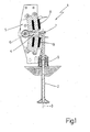
- electromagnets 8 are controlled by a control unit 11 to alternately or simultaneously exert a magnetic force of attraction on oscillating arm 4 to rotate it about axis 6 of rotation and so move valve 2, along longitudinal axis 3, between said fully-open and closed positions (not shown). More specifically, valve 2 is set to the closed position (not shown) when oscillating arm 4 rests on the bottom electromagnet 8; is set to the fully-open position (not shown) when oscillating arm 4 rests on the top electromagnet 8; and is set to a partially open position when electromagnets 8 are both deenergized and oscillating arm 4 is maintained in said intermediate position (shown in Figure 1 ) by spring 9.
- Oscillating arm 4 is located between the pole pieces 10 of the two electromagnets 8, which are fitted to support 5 in fixed positions a fixed distance D apart, so that the estimated value x(t) of the position of oscillating arm 4 can be calculated directly, by means of a simple algebraic sum operation, from an estimated value d(t) of the distance between a given point of oscillating arm 4 and a corresponding point of either one of electromagnets 8.
- the estimated value v(t) of the speed of oscillating arm 4 can be calculated directly from an estimated value of the speed between a given point of oscillating arm 4 and a corresponding point of either one of electromagnets 8.
- Constants K 0 , K 1 , K 2 , K 3 can be determined experimentally by means of a series of measurements of magnetic circuit 18.
- the conventional instant 0 is so selected as to accurately determine the value of the flux ⁇ (0) at instant 0, and, in particular, is normally selected within a time interval in which no current flows in coil 17, so that flux ⁇ is substantially zero (the effect of any residual magnetization is negligible), or is selected at a given position of oscillating arm 4 (typically, when oscillating arm 4 rests on pole pieces 10 of electromagnet 8) at which the value of position x and therefore of flux ⁇ is known.
Landscapes
- Engineering & Computer Science (AREA)
- Mechanical Engineering (AREA)
- General Engineering & Computer Science (AREA)
- Valve Device For Special Equipments (AREA)
- Magnetically Actuated Valves (AREA)
Claims (4)
- Ein Verfahren zum Abschätzen des magnetischen Flusses (ϕ) in einem elektromagnetischen Stellglied (1) zum Steuern eines Maschinenventils (2), das einen Betätigungskörper umfasst, d.h. einen Schwinghebel (4), der mindestens teilweise aus ferromagnetischem Material hergestellt ist, und in Richtung mindestens eines Elektromagneten (8) durch die magnetische Anziehungskraft bewegt wird, die durch den Elektromagneten (8) erzeugt wird, wobei das Verfahren die folgenden Schritte aufweist:Abschätzen des Wertes des magnetischen Flusses (ϕ) durch das Verwenden eines elektrischen Schaltkreises, der mit einem magnetischem Schaltkreis (18) verbunden ist, der durch den magnetischen Fluss (ϕ) beeinflusst wird und durch den Elektromagneten (8) sowie den Betätigungskörper definiert wird,Berechnen der zeitlichen Ableitung des magnetischen Flusses (ϕ) als eine Linearkombination der Werte der elektrischen Größen (va (t)) des elektrischen Schaltkreises, undIntegrieren der Ableitung des magnetischen Flusses (ϕ) über die Zeit,das Verfahren ist gekennzeichnet durch die folgenden Schritte:Messen der Spannung (va (t)) an den Anschlüssen einer Hilfsspule (22), die mit dem magnetischen Schaltkreis (18) verbunden ist, den magnetischen Fluss (ϕ) einbindet und im Wesentlichen elektrisch offen ist, undBerechnen der zeitlichen Ableitung des magnetischen Flusses (ϕ) und des magnetischen Flusses (ϕ) selbst gemäß der folgenden Gleichungen:


in denen:ϕ der magnetische Fluss ist,Na die Wicklungsanzahl der Hilfsspule (22), undva (t) die Spannung, die an den Anschlüssen der Hilfsspule (22) anliegt. - Ein Verfahren gemäß Anspruch 1, in dem die Ableitung des magnetischen Flusses (ϕ) über die Zeit integriert wird, wobei ein Anfangszeitpunkt verwendet wird, von dem aus die Integrationsoperation gestartet werden kann, während der Anfangszeitpunkt aus einem Zeitintervall ausgewählt wird, in dem sich der Betätigungskörper in einer vorgegebenen bekannten Position befindet.
- Ein Verfahren gemäß Anspruch 1, in dem die Ableitung des magnetischen Flusses (ϕ) über die Zeit integriert wird, wobei ein Anfangszeitpunkt verwendet wird, von dem aus die Integrationsoperation gestartet werden kann, während der Anfangszeitpunkt aus einem Zeitintervall ausgewählt wird, in dem der Elektromagnet (8) abgeschaltet wird.
- Eine Vorrichtung zum Abschätzen des magnetischen Flusses (ϕ) in einem elektromagnetischen Stellglied (1) zum Steuern eines Maschinenventils (2), in der
das elektromagnetische Stellglied (1) mindestens einen Elektromagneten (8) umfasst, um einen Betätigungskörper, d.h. einen Schwinghebel (4), der mindestens teilweise aus ferromagnetischem Material hergestellt ist, durch die magnetische Anziehungskraft zu bewegen, die durch den Elektromagneten (8) selbst erzeugt wird, während
der Elektromagnet (8) und der Antriebskörper einen magnetischen Schaltkreis (18) definieren, der durch den magnetischen Fluss (ϕ) beeinflusst wird, und
der Elektromagnet (8) weist einen elektrischen Schaltkreis auf, der mit dem magnetischen Schaltkreis (18) verbunden ist und mindestens teilweise den magnetischen Fluss (ϕ) einbindet, wobei
die Vorrichtung Abschätzmittel (15) mit Messmitteln (20, 21; 23) zum Messen der Werte umfasst, die durch elektrische Größen (va (t)) des elektrischen Schaltkreises (17; 22) angenommen werden, während die Abschätzmittel (15) den Wert des magnetischen Flusses (ϕ) durch Berechnen der zeitlichen Ableitung des magnetischen Flusses (ϕ) als eine Linearkombination der Werte der elektrischen Größen (va (t)) abschätzen, und die Ableitung des magnetischen Flusses (ϕ) über die Zeit integrieren,
die Vorrichtung ist dadurch gekennzeichnet, dass:die Abschätzmittel (15) eine Hilfsspule (22) umfassen, die mit dem magnetischen Schaltkreis (18) verbunden ist, den magnetischen Fluss (ϕ einbindet und im Wesentlichen elektrisch offen ist, unddie Messmittel (20, 21; 23) umfassen ein Spannungsmessgerät (23) zum Messen der Spannung (va (t)) an den Anschlüssen der Hilfsspule (22), wodurch die Werte der elektrischen Größen gemessen werden.
Applications Claiming Priority (2)
| Application Number | Priority Date | Filing Date | Title |
|---|---|---|---|
| ITBO000248 | 2000-05-04 | ||
| IT2000BO000248A IT1321182B1 (it) | 2000-05-04 | 2000-05-04 | Metodo e dispositivo per la stima del flusso magnetico in unazionatore elettromagnetico per il comando di una valvola di un motore |
Publications (3)
| Publication Number | Publication Date |
|---|---|
| EP1152251A2 EP1152251A2 (de) | 2001-11-07 |
| EP1152251A3 EP1152251A3 (de) | 2002-06-12 |
| EP1152251B1 true EP1152251B1 (de) | 2009-07-22 |
Family
ID=11438442
Family Applications (1)
| Application Number | Title | Priority Date | Filing Date |
|---|---|---|---|
| EP01110859A Expired - Lifetime EP1152251B1 (de) | 2000-05-04 | 2001-05-04 | Verfahren und Anlage zur Magnetfluss-Schätzung in einem elektromagnetischen Aktuator zur Steuerung eines Maschinenventils |
Country Status (6)
| Country | Link |
|---|---|
| US (1) | US6591204B2 (de) |
| EP (1) | EP1152251B1 (de) |
| BR (1) | BR0101919A (de) |
| DE (1) | DE60139289D1 (de) |
| ES (1) | ES2328788T3 (de) |
| IT (1) | IT1321182B1 (de) |
Families Citing this family (5)
| Publication number | Priority date | Publication date | Assignee | Title |
|---|---|---|---|---|
| ITBO20010077A1 (it) * | 2001-02-13 | 2002-08-13 | Magneti Marelli Spa | Metodo di stima della curva di magnetizzazione di un attuatore elettromagnetico per il comando di una valvola di un motore |
| ITBO20010760A1 (it) * | 2001-12-14 | 2003-06-16 | Magneti Marelli Powertrain Spa | Metodo per la stima della posizione e della velocita' di un corpo attuatore in un azionatore elettromagnetico per il comando di una valvola |
| US7248041B2 (en) * | 2003-07-28 | 2007-07-24 | Cummins, Inc. | Device and method for measuring transient magnetic performance |
| US20050076866A1 (en) * | 2003-10-14 | 2005-04-14 | Hopper Mark L. | Electromechanical valve actuator |
| US7089895B2 (en) * | 2005-01-13 | 2006-08-15 | Motorola, Inc. | Valve operation in an internal combustion engine |
Family Cites Families (8)
| Publication number | Priority date | Publication date | Assignee | Title |
|---|---|---|---|---|
| US3689828A (en) * | 1970-03-17 | 1972-09-05 | Hitachi Ltd | Manually controlled case depth measuring instrument with indicators to guide its use |
| DE4140586C2 (de) * | 1991-12-10 | 1995-12-21 | Clark Equipment Co N D Ges D S | Verfahren und Steuereinrichtung zur Steuerung des Stroms durch eine Magnetspule |
| JPH05280315A (ja) * | 1992-03-31 | 1993-10-26 | Isuzu Motors Ltd | 電磁駆動バルブ |
| AU4237096A (en) * | 1994-11-09 | 1997-05-29 | Aura Systems, Inc. | Hinged armature electromagnetically actuated valve |
| US5638781A (en) * | 1995-05-17 | 1997-06-17 | Sturman; Oded E. | Hydraulic actuator for an internal combustion engine |
| JPH09320841A (ja) * | 1996-05-28 | 1997-12-12 | Toyota Motor Corp | 電磁アクチュエータ制御装置 |
| US5991143A (en) * | 1998-04-28 | 1999-11-23 | Siemens Automotive Corporation | Method for controlling velocity of an armature of an electromagnetic actuator |
| US6249418B1 (en) * | 1999-01-27 | 2001-06-19 | Gary Bergstrom | System for control of an electromagnetic actuator |
-
2000
- 2000-05-04 IT IT2000BO000248A patent/IT1321182B1/it active
-
2001
- 2001-05-02 BR BR0101919-8A patent/BR0101919A/pt not_active IP Right Cessation
- 2001-05-04 US US09/848,553 patent/US6591204B2/en not_active Expired - Fee Related
- 2001-05-04 ES ES01110859T patent/ES2328788T3/es not_active Expired - Lifetime
- 2001-05-04 EP EP01110859A patent/EP1152251B1/de not_active Expired - Lifetime
- 2001-05-04 DE DE60139289T patent/DE60139289D1/de not_active Expired - Lifetime
Also Published As
| Publication number | Publication date |
|---|---|
| EP1152251A2 (de) | 2001-11-07 |
| IT1321182B1 (it) | 2003-12-30 |
| BR0101919A (pt) | 2001-12-26 |
| EP1152251A3 (de) | 2002-06-12 |
| DE60139289D1 (de) | 2009-09-03 |
| US6591204B2 (en) | 2003-07-08 |
| US20020084777A1 (en) | 2002-07-04 |
| ES2328788T3 (es) | 2009-11-18 |
| ITBO20000248A1 (it) | 2001-11-04 |
Similar Documents
| Publication | Publication Date | Title |
|---|---|---|
| EP1152129B1 (de) | Verfahren und Vorrichtung zur Lagebestimmung eines Ankers in einem elektromagnetischen Aktuator zur Steuerung eines Motorventils | |
| US6397797B1 (en) | Method of controlling valve landing in a camless engine | |
| US5818680A (en) | Apparatus for controlling armature movements in an electromagnetic circuit | |
| US6683775B2 (en) | Control method for an electromagnetic actuator for the control of an engine valve | |
| EP1152251B1 (de) | Verfahren und Anlage zur Magnetfluss-Schätzung in einem elektromagnetischen Aktuator zur Steuerung eines Maschinenventils | |
| US6644253B2 (en) | Method of controlling an electromagnetic valve actuator | |
| US6659422B2 (en) | Control method for an electromagnetic actuator for the control of a valve of an engine from a rest condition | |
| JPH09320841A (ja) | 電磁アクチュエータ制御装置 | |
| JP3614092B2 (ja) | 電磁駆動弁のバルブクリアランス推定装置及び制御装置 | |
| US6798636B2 (en) | Method of estimating the effect of the parasitic currents in an electromagnetic actuator for the control of an engine valve | |
| EP1231361B1 (de) | Verfahren zur Bestimmung der Magnetisierung eines elektromagnetischen Ventilsteuerungsaktuators | |
| EP1319807B1 (de) | Verfahren zum Abschätzen der Position und Geschwindigkeit eines Ankers in einem elektromagnetischen Aktor zur Steuerung eines Motorventils | |
| EP1271570B1 (de) | Regelverfahren eines elektromagnetischen Aktuators zur Steuerung eines Motorventils vom Positionsanschlag heraus | |
| EP1132580B1 (de) | Verfahren zum Schätzen der Endposition eines Ankers in einem elektromagnetischen Ventilaktor eines Ein-oder Ausslasventiels eine Brennkraftmaschine | |
| JP2003284369A (ja) | Emvaアマチュアの位置および速度を推定する方法 | |
| JP2001015329A (ja) | 電磁駆動弁のバルブクリアランス推定装置 |
Legal Events
| Date | Code | Title | Description |
|---|---|---|---|
| PUAI | Public reference made under article 153(3) epc to a published international application that has entered the european phase |
Free format text: ORIGINAL CODE: 0009012 |
|
| AK | Designated contracting states |
Kind code of ref document: A2 Designated state(s): AT BE CH CY DE DK ES FI FR GB GR IE IT LI LU MC NL PT SE TR |
|
| AX | Request for extension of the european patent |
Free format text: AL;LT;LV;MK;RO;SI |
|
| PUAL | Search report despatched |
Free format text: ORIGINAL CODE: 0009013 |
|
| AK | Designated contracting states |
Kind code of ref document: A3 Designated state(s): AT BE CH CY DE DK ES FI FR GB GR IE IT LI LU MC NL PT SE TR |
|
| AX | Request for extension of the european patent |
Free format text: AL;LT;LV;MK;RO;SI |
|
| 17P | Request for examination filed |
Effective date: 20021210 |
|
| AKX | Designation fees paid |
Designated state(s): DE ES FR GB SE |
|
| 17Q | First examination report despatched |
Effective date: 20070531 |
|
| GRAP | Despatch of communication of intention to grant a patent |
Free format text: ORIGINAL CODE: EPIDOSNIGR1 |
|
| RAP1 | Party data changed (applicant data changed or rights of an application transferred) |
Owner name: MAGNETI MARELLI POWERTRAIN S.P.A. |
|
| RAP1 | Party data changed (applicant data changed or rights of an application transferred) |
Owner name: MAGNETI MARELLI HOLDING S.P.A. |
|
| RAP1 | Party data changed (applicant data changed or rights of an application transferred) |
Owner name: MAGNETI MARELLI S.P.A. |
|
| GRAS | Grant fee paid |
Free format text: ORIGINAL CODE: EPIDOSNIGR3 |
|
| GRAA | (expected) grant |
Free format text: ORIGINAL CODE: 0009210 |
|
| AK | Designated contracting states |
Kind code of ref document: B1 Designated state(s): DE ES FR GB SE |
|
| REG | Reference to a national code |
Ref country code: GB Ref legal event code: FG4D |
|
| REF | Corresponds to: |
Ref document number: 60139289 Country of ref document: DE Date of ref document: 20090903 Kind code of ref document: P |
|
| REG | Reference to a national code |
Ref country code: SE Ref legal event code: TRGR |
|
| REG | Reference to a national code |
Ref country code: ES Ref legal event code: FG2A Ref document number: 2328788 Country of ref document: ES Kind code of ref document: T3 |
|
| PLBE | No opposition filed within time limit |
Free format text: ORIGINAL CODE: 0009261 |
|
| STAA | Information on the status of an ep patent application or granted ep patent |
Free format text: STATUS: NO OPPOSITION FILED WITHIN TIME LIMIT |
|
| 26N | No opposition filed |
Effective date: 20100423 |
|
| PGFP | Annual fee paid to national office [announced via postgrant information from national office to epo] |
Ref country code: ES Payment date: 20100611 Year of fee payment: 10 |
|
| PGFP | Annual fee paid to national office [announced via postgrant information from national office to epo] |
Ref country code: SE Payment date: 20100531 Year of fee payment: 10 Ref country code: GB Payment date: 20100527 Year of fee payment: 10 |
|
| PGFP | Annual fee paid to national office [announced via postgrant information from national office to epo] |
Ref country code: FR Payment date: 20110621 Year of fee payment: 11 |
|
| PGFP | Annual fee paid to national office [announced via postgrant information from national office to epo] |
Ref country code: DE Payment date: 20110505 Year of fee payment: 11 |
|
| REG | Reference to a national code |
Ref country code: SE Ref legal event code: EUG |
|
| GBPC | Gb: european patent ceased through non-payment of renewal fee |
Effective date: 20110504 |
|
| PG25 | Lapsed in a contracting state [announced via postgrant information from national office to epo] |
Ref country code: GB Free format text: LAPSE BECAUSE OF NON-PAYMENT OF DUE FEES Effective date: 20110504 |
|
| REG | Reference to a national code |
Ref country code: ES Ref legal event code: FD2A Effective date: 20121116 |
|
| PG25 | Lapsed in a contracting state [announced via postgrant information from national office to epo] |
Ref country code: ES Free format text: LAPSE BECAUSE OF NON-PAYMENT OF DUE FEES Effective date: 20110505 |
|
| REG | Reference to a national code |
Ref country code: FR Ref legal event code: ST Effective date: 20130131 |
|
| REG | Reference to a national code |
Ref country code: DE Ref legal event code: R119 Ref document number: 60139289 Country of ref document: DE Effective date: 20121201 |
|
| PG25 | Lapsed in a contracting state [announced via postgrant information from national office to epo] |
Ref country code: SE Free format text: LAPSE BECAUSE OF NON-PAYMENT OF DUE FEES Effective date: 20110505 Ref country code: FR Free format text: LAPSE BECAUSE OF NON-PAYMENT OF DUE FEES Effective date: 20120531 |
|
| PG25 | Lapsed in a contracting state [announced via postgrant information from national office to epo] |
Ref country code: DE Free format text: LAPSE BECAUSE OF NON-PAYMENT OF DUE FEES Effective date: 20121201 |