EP1106841A2 - Actionneur de positionnement linéaire - Google Patents
Actionneur de positionnement linéaire Download PDFInfo
- Publication number
- EP1106841A2 EP1106841A2 EP00126738A EP00126738A EP1106841A2 EP 1106841 A2 EP1106841 A2 EP 1106841A2 EP 00126738 A EP00126738 A EP 00126738A EP 00126738 A EP00126738 A EP 00126738A EP 1106841 A2 EP1106841 A2 EP 1106841A2
- Authority
- EP
- European Patent Office
- Prior art keywords
- locking
- piston
- adjustment drive
- linear adjustment
- drive according
- Prior art date
- Legal status (The legal status is an assumption and is not a legal conclusion. Google has not performed a legal analysis and makes no representation as to the accuracy of the status listed.)
- Withdrawn
Links
Images

Classifications
-
- F—MECHANICAL ENGINEERING; LIGHTING; HEATING; WEAPONS; BLASTING
- F15—FLUID-PRESSURE ACTUATORS; HYDRAULICS OR PNEUMATICS IN GENERAL
- F15B—SYSTEMS ACTING BY MEANS OF FLUIDS IN GENERAL; FLUID-PRESSURE ACTUATORS, e.g. SERVOMOTORS; DETAILS OF FLUID-PRESSURE SYSTEMS, NOT OTHERWISE PROVIDED FOR
- F15B15/00—Fluid-actuated devices for displacing a member from one position to another; Gearing associated therewith
- F15B15/20—Other details, e.g. assembly with regulating devices
- F15B15/26—Locking mechanisms
- F15B15/261—Locking mechanisms using positive interengagement, e.g. balls and grooves, for locking in the end positions
-
- F—MECHANICAL ENGINEERING; LIGHTING; HEATING; WEAPONS; BLASTING
- F15—FLUID-PRESSURE ACTUATORS; HYDRAULICS OR PNEUMATICS IN GENERAL
- F15B—SYSTEMS ACTING BY MEANS OF FLUIDS IN GENERAL; FLUID-PRESSURE ACTUATORS, e.g. SERVOMOTORS; DETAILS OF FLUID-PRESSURE SYSTEMS, NOT OTHERWISE PROVIDED FOR
- F15B15/00—Fluid-actuated devices for displacing a member from one position to another; Gearing associated therewith
- F15B15/20—Other details, e.g. assembly with regulating devices
- F15B15/26—Locking mechanisms
- F15B15/262—Locking mechanisms using friction, e.g. brake pads
- F15B15/264—Screw mechanisms attached to the piston
Definitions
- the invention relates to a linear adjustment drive, as described in the preamble of claim 1.
- Such a linear adjustment drive is as with a Pressurized, double-acting hydraulic cylinder with locking device from US 4,481,864 A, in which a tubular piston rod as a working piston is formed and secured against rotation in a pressure cylinder by pressurization is arranged linearly adjustable by a medium. In and with the piston rod A threaded spindle is arranged in a motion-connected manner Thread engagement is available.
- the spindle nut is part of a threaded spindle Rotating part, which is rotatably mounted in an end housing of the printing cylinder and on which Gear is arranged rotatably, with which a switchable pawl arrangement for blocking the rotary movement can be brought into engagement.
- a linear adjustment of the against rotation secured piston there is a rotary movement of the rotating part, which is caused by the pawl arrangement and can be blocked by the gearwheel, so that the further linear movement of the piston is prevented.
- the disadvantage of this training is the large number of concentric components arranged in relation to each other, so that with large external dimensions and this means that the unit's high weight is only technically necessary for the highest adjustment forces and can be used economically.
- the object of the invention is to provide such a linear adjustment drive, in particular one with cylinder-piston unit which can be acted upon by a pressure medium, with a locking arrangement create that is technically easy to implement and requires little space and is easy to install and requires no specialist knowledge.
- This object of the invention is represented by the characterizing part of claim 1 Characteristics achieved.
- the surprising advantage is that the immediate Storage of the threaded spindle or a locking sleeve rotatably connected to it in End housing and the direct drive connection of the threaded spindle via the internal thread of the piston, the dimensioning of the adjustment drive with high adjustment forces is kept small and the constructional and manufacturing expenditure is reduced and compared to known security measures to avoid unintentional adjustment movements with such drives of systems and devices a high level of economy is achieved.
- An advantage here is a training according to claim 2, because it makes a compact unit is achieved and the assembly security and assembly effort by integrating the Control unit in the end housing by eliminating external control elements and thus more vulnerable Pressure lines and electrical control lines can be optimized.
- training according to claim 3 is advantageous because it allows sensitive controllability the adjustment speed is reached and for a continuous, jerk-free adjustment a corresponding system pressure can be set.
- the advantageous training given in claim 12 is sufficient Bearing dimension to absorb high forces, especially the axial forces, reached.
- the design according to claim 19 ensures a working surface of the piston, one corresponds to the circular area given by the inner diameter of the cylinder jacket.
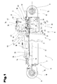
- 1 and 2 is a linear adjustment drive 1, in particular one with a pressure medium actable, double-acting cylinder-piston unit 2, shown.
- This is with one Locking arrangement 3 equipped with a mechanical fixation in end and intermediate positions an adjustment path is reached.
- the cylinder-piston unit 2 consists of a cylinder jacket 4, formed by a tube 5, which has a cylinder end adapter 7 at an end 6.
- an end housing 9 is arranged in an opposite End 8 is firmly connected to the cylinder jacket 4, e.g. screwed, welded etc.
- the end housing 9 has a bearing head 10 provided, e.g. a radial spherical plain bearing 11 is arranged for receiving a bearing pin 12 is.
- the cylinder end adapter 7 arranged at the opposite end 6 is in a bore 13 extends through a tubular piston rod 14, which is connected to a further bearing head 15 firmly connected, e.g. welded, is.
- This bearing head 15 also has e.g. another radial spherical plain bearing 16 for receiving a bearing pin 17. This enables the linear actuator 1 for adjusting two parts of the device which can be moved linearly relative to one another within a predetermined adjustment path can be used.
- the tubular piston rod 14, which extends the pressure space 18, is annular Piston 19 connected in a fixed manner.
- One the piston 19 in an annular circumferential Groove 20 comprising sealing arrangement 21 forms a pressure-tight subdivision of the pressure space 18 and thus the double-acting design of the cylinder-piston unit 2.
- the end housing 9 is steppedly offset in a concentric to a cylinder longitudinal center axis 22 Bore 23 a bearing arrangement formed from radial bearing 24 and axial thrust bearing 25 26 for the rotatable mounting of a bearing extension 27 in the tubular piston rod 14 extending threaded spindle 28 is provided.
- the threaded spindle 28 has a External thread 29, e.g. a trapezoidal thread on.
- the external thread 29 of the threaded spindle 28 is in engagement with an internal thread 30, which is in a to the longitudinal axis of the cylinder 22 concentrically extending opening 31 of the annular piston 19 is arranged is.
- the piston 19 is subjected to a Pressure medium in the cylinder jacket 4 moves linearly and this is secured against rotation, the external and internal threads 29, 30 engage in a rotational movement the threaded spindle 28 in accordance with the predetermined ratios of the pitch of the thread and the distance covered.
- the bearing extension 27 of the threaded spindle 28 consists of one piece the threaded spindle 28 integrally formed cylindrical bearing journal 32 and one concentrically comprehensive and rotatably connected to the bearing pin 32 locking sleeve 33 for the Locking arrangement 3.
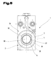
- the end housing 9, in which the threaded spindle 28 is rotatably supported via the bearing arrangement 26 and in which the locking arrangement 3 for blocking the rotational movement of the threaded spindle 28 is arranged, furthermore has all for the operation of the linear adjustment drive 1 required flow and connection channels 34 for the application of the cylinder-piston unit 2 and the locking arrangement 3 for applying the pressure medium as well as the internal ones required directly for the operation of the linear adjustment drive 1 Regulators 35 on.
- the locking arrangement 3 is in the end housing 9 in one with the pressure medium actable cylindrical bore 36 in a perpendicular to the cylinder longitudinal center axis 22 extending direction adjustable locking piston 37 and circumferentially by a Locking extension 38 of the control piston 37 associated locking receptacles 39 in a surface 40 the locking sleeve 33 and the journal 32 are formed.
- the locking piston 37 is via a spring arrangement 41 in the direction of the surface 40 of the bearing sleeve which has the locking receptacle 39 33 preloaded, with which a mechanically acting safeguard against twisting the Threaded spindle 28 is reached when the locking extension 38 engages in the locking receptacle 39.
- the blocking effect is canceled by acting on the blocking piston 37 with the Pressure medium in a direction opposite to the spring force - according to arrow 42 - in other words a direction radial to the longitudinal axis 22 of the cylinder.
- the application of the locking piston 37 with the pressure medium takes place via the holes in the end housing 9 43 formed supply channels 44 and the flow and connection channels 34 and the respective control members 35, which are based on a hydraulic scheme in the following are still explained.
- the supply and discharge of the pressure medium takes place via those provided in the end housing Input and output ports 45 and pressure lines 46 e.g. Pressure pipes, hoses Etc.
- the locking arrangement 3 causes the locking piston 37 to be in the rest position, that is to say when it is in sequence the spring force - according to arrow 42 - the spring assembly 41 with its locking extension 38 in the Locking receptacle 39 of the locking sleeve 33 engages, a mechanical blocking against rotation the threaded spindle 28.
- the threaded engagement between the piston 19 and the Threaded spindle 28 is thus a linear movement of the piston 21 and thus the Piston rod 14 together with bearing head 15 both when pressure chamber 18 is acted upon with the pressure medium, as well as by acting on the linear adjustment drive 1 external force, e.g. Lifting capacity, prevented.
- This mechanical fuse is also in one depressurized state, i.e. when no pressurized medium acts on the piston 21, effective. This can be used for a number of devices, e.g. Lifting platforms, cranes etc., specified security requirements to protect users, operating personnel etc. are met.
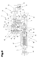
- FIG. 3 is in the form of a schematic representation of the linear adjustment drive 1 with a Control unit 47 with the flow and connection channels integrated in the end housing 9 34 and control members 35 are shown, the control members 35 in the for such Representations of the usual form of circuit symbols are shown.
- the linear actuator 1 a compact design, whereby the installation is simplified and after the installation of the linear adjustment drive 1 in an indicated Device 48 this by means of the pressure lines 46, e.g. Pressure pipes 49, pressure hoses etc. to be connected to a control valve 50.
- This control valve 50 is fluidly connected with a supply device 51 for the medium, which means from a tank 52 a pump 53 and a flow line 54 is supplied.
- a return line 55 connects the control valve 50 with the tank 52 for returning the pressure medium.
- the end housing 9 has 49 connections 56, 57 for connecting the pressure lines generally formed by holes with an internal thread for receiving screw connections are and of which in the end housing 9 which are shown schematically in full lines Continue flow and connection channels 34.
- the function of the entire control unit 47 arranged in the end housing 9 is integrated the corresponding control members 35 is an example of an extension process below the piston rod 14 up to an intermediate position to be held after an adjustment path 58, as shown in dashed lines. It is to carry out this adjustment process required to have the piston 19 on a piston surface 59 facing the end housing 9 the pressure medium - according to arrow 60.
- the control valve 50 which can be done manually or automatically, is that which is pumped by the pump 53 Pressure medium and the pressure line 49 the corresponding port 57 and thus the corresponding flow and supply channels 34 supplied.
- the print medium will after entering the end housing in a supply channel 61 to act on the piston 19 and another supply channel 62 branches through which the pressure medium the blocking piston 37 arranged in the bore 36 is fed.
- the application of the Locking piston 37 takes place in one of the locking receptacles 39 of the threaded spindle 28 or Locking sleeve 33 facing pressure chamber 63, whereby an adjustment of the locking piston 37th takes place against the action of the spring arrangement 41.
- the locking extension 38 is made the area of the locking receptacles 39, thereby blocking the rotational movement the threaded spindle 28 is canceled and thus a linear movement of the piston 19th can be done.
- a controllable throttle check valve 64 which is arranged in the flow direction to the piston 19 releases an unimpeded flow of the pressure medium.
- spring-loaded check valve 65 is arranged, which is also in the direction of flow of the pressure medium to the piston 19 opens and thus releases the flow freely. Due to the pressure build-up in the pressure chamber 18, the linear adjustment movement of the piston now takes place 19 and thus the piston rod 14, for which purpose, however, the pressure medium from a cylinder space 66, which is separated from the pressure chamber 18 by the piston 19, displaces i.e. must be derived.
- the Arrangement of the check valves 65, 68 in the end housing 9 is with a central axis 71 of Control piston 69 selected in alignment, whereby the control piston 69 outstanding on both sides Switch pins 72 when adjusting the control piston 69 directly to spring-loaded locking elements 73, e.g. Balls of the check valves 65, 68, act to flow through Allow blocking direction.
- spring-loaded locking elements 73 e.g. Balls of the check valves 65, 68
- FIG. 4 is a detail of the threaded spindle 28 with the locking sleeve 33 and in one of the locking receptacles 39 engaging locking projection 38 shown.
- How an arc length 77 of the locking receptacle 39 is greater than a diameter 78 the locking extension 38 selected which creates a game for the engagement in the direction of rotation of the threaded spindle 28 is reached, which facilitates the locking process, but due to the drive reduction only minor effects on the accuracy of the positioning process in the thread Has.
- the anti-rotation device is provided, that for the absorption of the torque between the threaded spindle 28 and the piston rod 14 is required in the device 48 and the articulation designed for this purpose Cylinder-piston unit 2 by means of the bearing heads 10, 15 and bearing bolts 12, 17.
- FIG. 5 schematically shows a further embodiment of the linear adjustment drive 1, in which an internal anti-rotation device 79 for receiving the between threaded spindle 28 and the piston 19 designed as a spindle nut or the piston rod connected to it 14 occurring torque is provided to accommodate it.
- the piston rod has e.g. diametrically opposed, longitudinal Guide surfaces 80, 81.
- a breakthrough 82 of the cylinder end adapter 7 is corresponding
- the cross-sectional shape of the piston rod 14 is formed and thus forms a guide arrangement 83 secured against rotation by the piston rod 14 with respect to the cylinder and thus the torque arising in the threaded connection is absorbed.
- FIGS. 1, 2, 3; 4; 5 versions shown the subject form independent, inventive solutions.
- the relevant, according to the invention Tasks and solutions are to the detailed descriptions of these figures remove.
Landscapes
- Engineering & Computer Science (AREA)
- Physics & Mathematics (AREA)
- Fluid Mechanics (AREA)
- Mechanical Engineering (AREA)
- General Engineering & Computer Science (AREA)
- Actuator (AREA)
Applications Claiming Priority (3)
| Application Number | Priority Date | Filing Date | Title |
|---|---|---|---|
| AT84699U | 1999-12-07 | ||
| AT84699 | 1999-12-07 | ||
| AT0084699U AT4094U1 (de) | 1999-12-07 | 1999-12-07 | Linearverstellantrieb |
Publications (2)
| Publication Number | Publication Date |
|---|---|
| EP1106841A2 true EP1106841A2 (fr) | 2001-06-13 |
| EP1106841A3 EP1106841A3 (fr) | 2003-09-24 |
Family
ID=3501129
Family Applications (1)
| Application Number | Title | Priority Date | Filing Date |
|---|---|---|---|
| EP00126738A Withdrawn EP1106841A3 (fr) | 1999-12-07 | 2000-12-06 | Actionneur de positionnement linéaire |
Country Status (2)
| Country | Link |
|---|---|
| EP (1) | EP1106841A3 (fr) |
| AT (1) | AT4094U1 (fr) |
Cited By (14)
| Publication number | Priority date | Publication date | Assignee | Title |
|---|---|---|---|---|
| EP1170512A1 (fr) * | 2000-07-06 | 2002-01-09 | Bümach Engineering International B.V. | Vérin à fluide sous pression avec verrouillage mécanique lorsque non pressurisé |
| EP1538344A3 (fr) * | 2003-12-04 | 2005-08-10 | Neumeister Hydraulik GmbH | Vérin verrouillable |
| EP1538343A3 (fr) * | 2003-12-04 | 2005-08-10 | Neumeister Hydraulik GmbH | Vérin verrouillable |
| EP1541876A3 (fr) * | 2003-12-04 | 2005-08-10 | Neumeister Hydraulik GmbH | Cylindre de verrouillage |
| WO2006103031A1 (fr) | 2005-03-31 | 2006-10-05 | Aros Hydraulik Gmbh | Cylindre de travail verrouillable |
| EP1710449A1 (fr) * | 2005-04-08 | 2006-10-11 | Neumeister Hydraulik GmbH | Vérin simple effet verrouillable |
| WO2008037412A1 (fr) * | 2006-09-28 | 2008-04-03 | Aros Hydraulik Gmbh | Cylindre de travail pouvant être bloqué |
| WO2008012082A3 (fr) * | 2006-07-25 | 2008-06-05 | Aros Hydraulik | Système de commande pour un élément hydraulique |
| EP2039944A2 (fr) | 2007-09-21 | 2009-03-25 | Weber-Hydraulik GmbH | Actionneur linéaire, en particulier unité cylindre-piston dotée d'un dispositif de verrouillage |
| EP1803943A3 (fr) * | 2005-12-29 | 2009-04-08 | Bümach Engineering International B.V. | Vérin avec verrouillage de position mécanique en cas d'absence de pression |
| DE102006030617B4 (de) * | 2005-12-29 | 2009-09-10 | Bümach Engineering International B.V. | Druckmittelbetriebener Arbeitszylinder mit mechanischer Wegsperrung im drucklosen Zustand |
| CN106286466A (zh) * | 2016-10-28 | 2017-01-04 | 中国船舶科学研究中心(中国船舶重工集团公司第七0二研究所) | 一种双作用双出杆初末位机械锁紧油缸 |
| CN110645290A (zh) * | 2019-10-25 | 2020-01-03 | 无锡英特帕普威孚液压有限责任公司 | 一种带制动功能的取力器 |
| EP4209685A1 (fr) | 2022-01-07 | 2023-07-12 | HYDAC Systems & Services GmbH | Dispositif de verrouillage |
Families Citing this family (4)
| Publication number | Priority date | Publication date | Assignee | Title |
|---|---|---|---|---|
| ITTO20011066A1 (it) * | 2001-11-13 | 2002-02-13 | Rolfo Spa | Attuatore lineare con bloccaggio meccanico interno. |
| AT503408B1 (de) | 2006-04-07 | 2008-06-15 | Weber Hydraulik Gmbh | Fluidzylinder-anordnung |
| DE102015214037B4 (de) * | 2015-07-24 | 2022-08-04 | Bayerische Motoren Werke Aktiengesellschaft | Parksperre |
| CN112271432B (zh) * | 2020-10-09 | 2022-04-05 | 中国电子科技集团公司第三十八研究所 | 一种升降式快速定位旋锁 |
Family Cites Families (7)
| Publication number | Priority date | Publication date | Assignee | Title |
|---|---|---|---|---|
| US2804054A (en) * | 1954-09-13 | 1957-08-27 | Gen Motors Corp | Actuator and locking means therefor |
| US3274902A (en) * | 1965-10-22 | 1966-09-27 | Deere & Co | Hydraulic control system |
| CH546895A (de) * | 1971-10-21 | 1974-03-15 | Bieri H Ag | Doppelwirkendes hydraulisches kolben- zylinderaggregat mit ruecklaufsperre. |
| DE2158094A1 (de) * | 1971-11-24 | 1973-05-30 | Zahnradfabrik Friedrichshafen | Stellantrieb fuer winkelverstellungen |
| IT1142782B (it) * | 1981-07-21 | 1986-10-15 | Selenia Ind Elettroniche | Martinetto idraulico con blocco meccanico di sicurezza |
| FR2534985A3 (fr) * | 1982-10-23 | 1984-04-27 | Messerschmitt Boelkow Blohm | Verin a blocage perfectionne |
| EP0322503A3 (fr) * | 1987-12-29 | 1991-09-25 | Daihatsu Diesel Mfg. Co., Ltd. | Appareil à fluide |
-
1999
- 1999-12-07 AT AT0084699U patent/AT4094U1/de not_active IP Right Cessation
-
2000
- 2000-12-06 EP EP00126738A patent/EP1106841A3/fr not_active Withdrawn
Cited By (19)
| Publication number | Priority date | Publication date | Assignee | Title |
|---|---|---|---|---|
| EP1170512A1 (fr) * | 2000-07-06 | 2002-01-09 | Bümach Engineering International B.V. | Vérin à fluide sous pression avec verrouillage mécanique lorsque non pressurisé |
| EP1538344A3 (fr) * | 2003-12-04 | 2005-08-10 | Neumeister Hydraulik GmbH | Vérin verrouillable |
| EP1538343A3 (fr) * | 2003-12-04 | 2005-08-10 | Neumeister Hydraulik GmbH | Vérin verrouillable |
| EP1541876A3 (fr) * | 2003-12-04 | 2005-08-10 | Neumeister Hydraulik GmbH | Cylindre de verrouillage |
| JP2008534874A (ja) * | 2005-03-31 | 2008-08-28 | アロース ハイドラウリク ゲーエムベーハー | 停止可能な作動シリンダー |
| WO2006103031A1 (fr) | 2005-03-31 | 2006-10-05 | Aros Hydraulik Gmbh | Cylindre de travail verrouillable |
| EP1710449A1 (fr) * | 2005-04-08 | 2006-10-11 | Neumeister Hydraulik GmbH | Vérin simple effet verrouillable |
| DE102006030617B4 (de) * | 2005-12-29 | 2009-09-10 | Bümach Engineering International B.V. | Druckmittelbetriebener Arbeitszylinder mit mechanischer Wegsperrung im drucklosen Zustand |
| EP1803943A3 (fr) * | 2005-12-29 | 2009-04-08 | Bümach Engineering International B.V. | Vérin avec verrouillage de position mécanique en cas d'absence de pression |
| WO2008012082A3 (fr) * | 2006-07-25 | 2008-06-05 | Aros Hydraulik | Système de commande pour un élément hydraulique |
| WO2008037412A1 (fr) * | 2006-09-28 | 2008-04-03 | Aros Hydraulik Gmbh | Cylindre de travail pouvant être bloqué |
| EP2039944A2 (fr) | 2007-09-21 | 2009-03-25 | Weber-Hydraulik GmbH | Actionneur linéaire, en particulier unité cylindre-piston dotée d'un dispositif de verrouillage |
| EP2039944A3 (fr) * | 2007-09-21 | 2012-09-26 | Weber-Hydraulik GmbH | Actionneur linéaire, en particulier unité cylindre-piston dotée d'un dispositif de verrouillage |
| CN106286466A (zh) * | 2016-10-28 | 2017-01-04 | 中国船舶科学研究中心(中国船舶重工集团公司第七0二研究所) | 一种双作用双出杆初末位机械锁紧油缸 |
| CN106286466B (zh) * | 2016-10-28 | 2018-02-23 | 中国船舶科学研究中心(中国船舶重工集团公司第七0二研究所) | 一种双作用双出杆初末位机械锁紧油缸 |
| CN110645290A (zh) * | 2019-10-25 | 2020-01-03 | 无锡英特帕普威孚液压有限责任公司 | 一种带制动功能的取力器 |
| CN110645290B (zh) * | 2019-10-25 | 2024-05-31 | 无锡英特帕普威孚液压有限责任公司 | 一种带制动功能的取力器 |
| EP4209685A1 (fr) | 2022-01-07 | 2023-07-12 | HYDAC Systems & Services GmbH | Dispositif de verrouillage |
| DE102022000062A1 (de) | 2022-01-07 | 2023-07-13 | Hydac Systems & Services Gmbh | Verriegelungsvorrichtung |
Also Published As
| Publication number | Publication date |
|---|---|
| EP1106841A3 (fr) | 2003-09-24 |
| AT4094U1 (de) | 2001-01-25 |
Similar Documents
| Publication | Publication Date | Title |
|---|---|---|
| EP1106841A2 (fr) | Actionneur de positionnement linéaire | |
| DE2904403C2 (fr) | ||
| EP0836982A2 (fr) | Clapet amortisseur | |
| DE2056066B2 (de) | Abschalteinrichtung für die hydraulische Hilfskraft bei einer Hilfskraftlenkung für Fahrzeuge | |
| EP0505349B2 (fr) | Vérin hydraulique | |
| DE2758074C2 (de) | Ventilanordnung für den Anschluß von Druckquellen an hydraulisch betätigbare Arbeitszylinder | |
| DE2833924A1 (de) | Hydraulische schaltgruppe | |
| DE3135098A1 (de) | Ventilaufbau, umfassend ein pumpensteuer- bzw. -regelventil und eine entlastungsanordnung | |
| DE10356598B3 (de) | Verriegelungszylinder | |
| DE2718190A1 (de) | Hydraulische kolben-zylinder-anordnung zum kippen des fahrerhauses eines lastkraftwagens | |
| DE10356596B3 (de) | Verriegelungszylinder | |
| EP2044336B1 (fr) | Système de commande pour un élément hydraulique | |
| EP0163771A2 (fr) | Soupape de verrouillage pour frein de descente | |
| DE3239255A1 (de) | Ventil | |
| DE2240012A1 (de) | Steuereinrichtung fuer hydrostatische lenkungen u.dgl | |
| DE2833971C2 (de) | Leitungsbruchsicherungs-Vorrichtung zur Anordnung zwischen einem hydraulischen Steuergerät und wenigstens einem Arbeitszylinder | |
| DE10356597B3 (de) | Verriegelungszylinder | |
| DE102016119251A1 (de) | Hydromechanischer Verriegelungszylinder und hydraulisches Steuersystem zu dessen Betätigung | |
| DE102019219603B3 (de) | Ventilmodul für eine hydraulische Kippvorrichtung eines Solarpaneelträgers und Solarpaneelträger | |
| DE19954577C1 (de) | Liftzylindereinheit für eine Hebebühne | |
| DE2519973C3 (de) | Entlastungsventil | |
| DE102019218402B4 (de) | Federdom für ein Hydraulikventil und Hydraulikventil mit einem solchen Federdom | |
| DE2450330B2 (de) | Doppelhydraulischer stellantrieb | |
| DE69625209T2 (de) | Hydraulisches ventilsystem | |
| DE102008035212A1 (de) | Hydraulische Ventilvorrichtung |
Legal Events
| Date | Code | Title | Description |
|---|---|---|---|
| PUAI | Public reference made under article 153(3) epc to a published international application that has entered the european phase |
Free format text: ORIGINAL CODE: 0009012 |
|
| AK | Designated contracting states |
Kind code of ref document: A2 Designated state(s): AT BE CH CY DE DK ES FI FR GB GR IE IT LI LU MC NL PT SE TR |
|
| AX | Request for extension of the european patent |
Free format text: AL;LT;LV;MK;RO;SI |
|
| PUAL | Search report despatched |
Free format text: ORIGINAL CODE: 0009013 |
|
| AK | Designated contracting states |
Kind code of ref document: A3 Designated state(s): AT BE CH CY DE DK ES FI FR GB GR IE IT LI LU MC NL PT SE TR |
|
| AX | Request for extension of the european patent |
Extension state: AL LT LV MK RO SI |
|
| STAA | Information on the status of an ep patent application or granted ep patent |
Free format text: STATUS: THE APPLICATION IS DEEMED TO BE WITHDRAWN |
|
| 18D | Application deemed to be withdrawn |
Effective date: 20030701 |