EP1106878A2 - Joint d'étanchéité à faible frottement, en particulier pour palier à roulement, et sa méthode de fabrication - Google Patents
Joint d'étanchéité à faible frottement, en particulier pour palier à roulement, et sa méthode de fabrication Download PDFInfo
- Publication number
- EP1106878A2 EP1106878A2 EP00127000A EP00127000A EP1106878A2 EP 1106878 A2 EP1106878 A2 EP 1106878A2 EP 00127000 A EP00127000 A EP 00127000A EP 00127000 A EP00127000 A EP 00127000A EP 1106878 A2 EP1106878 A2 EP 1106878A2
- Authority
- EP
- European Patent Office
- Prior art keywords
- lip
- seal assembly
- sealing
- ptfe
- members
- Prior art date
- Legal status (The legal status is an assumption and is not a legal conclusion. Google has not performed a legal analysis and makes no representation as to the accuracy of the status listed.)
- Withdrawn
Links
- 238000004519 manufacturing process Methods 0.000 title claims description 7
- 238000007789 sealing Methods 0.000 claims abstract description 37
- 229920001343 polytetrafluoroethylene Polymers 0.000 claims abstract description 24
- 239000004810 polytetrafluoroethylene Substances 0.000 claims abstract description 24
- 239000000243 solution Substances 0.000 claims abstract description 14
- 238000000034 method Methods 0.000 claims abstract description 9
- 238000005507 spraying Methods 0.000 claims abstract description 7
- 239000002184 metal Substances 0.000 claims abstract description 6
- 230000000379 polymerizing effect Effects 0.000 claims abstract description 4
- 239000007864 aqueous solution Substances 0.000 claims abstract description 3
- 238000011065 in-situ storage Methods 0.000 claims description 8
- 238000003780 insertion Methods 0.000 claims description 8
- 230000037431 insertion Effects 0.000 claims description 8
- 239000013536 elastomeric material Substances 0.000 claims description 4
- 238000006116 polymerization reaction Methods 0.000 claims description 4
- 239000002243 precursor Substances 0.000 claims description 4
- 239000000178 monomer Substances 0.000 claims description 3
- 239000004636 vulcanized rubber Substances 0.000 abstract 1
- 229920006362 Teflon® Polymers 0.000 description 6
- 238000012360 testing method Methods 0.000 description 6
- 239000004809 Teflon Substances 0.000 description 5
- 238000000576 coating method Methods 0.000 description 4
- 230000000712 assembly Effects 0.000 description 3
- 238000000429 assembly Methods 0.000 description 3
- 238000010586 diagram Methods 0.000 description 3
- 239000011248 coating agent Substances 0.000 description 2
- 238000005461 lubrication Methods 0.000 description 2
- 229920000642 polymer Polymers 0.000 description 2
- 238000004073 vulcanization Methods 0.000 description 2
- 239000003795 chemical substances by application Substances 0.000 description 1
- 230000006835 compression Effects 0.000 description 1
- 238000007906 compression Methods 0.000 description 1
- 239000003344 environmental pollutant Substances 0.000 description 1
- 239000000446 fuel Substances 0.000 description 1
- 239000004519 grease Substances 0.000 description 1
- 239000011499 joint compound Substances 0.000 description 1
- 239000000463 material Substances 0.000 description 1
- 238000012986 modification Methods 0.000 description 1
- 230000004048 modification Effects 0.000 description 1
- CWQXQMHSOZUFJS-UHFFFAOYSA-N molybdenum disulfide Chemical compound S=[Mo]=S CWQXQMHSOZUFJS-UHFFFAOYSA-N 0.000 description 1
- 239000012188 paraffin wax Substances 0.000 description 1
- 239000004033 plastic Substances 0.000 description 1
- 231100000719 pollutant Toxicity 0.000 description 1
- -1 polytetrafluoroethylene Polymers 0.000 description 1
- 230000003068 static effect Effects 0.000 description 1
- XLYOFNOQVPJJNP-UHFFFAOYSA-N water Substances O XLYOFNOQVPJJNP-UHFFFAOYSA-N 0.000 description 1
Images
Classifications
-
- F—MECHANICAL ENGINEERING; LIGHTING; HEATING; WEAPONS; BLASTING
- F16—ENGINEERING ELEMENTS AND UNITS; GENERAL MEASURES FOR PRODUCING AND MAINTAINING EFFECTIVE FUNCTIONING OF MACHINES OR INSTALLATIONS; THERMAL INSULATION IN GENERAL
- F16J—PISTONS; CYLINDERS; SEALINGS
- F16J15/00—Sealings
- F16J15/16—Sealings between relatively-moving surfaces
- F16J15/32—Sealings between relatively-moving surfaces with elastic sealings, e.g. O-rings
- F16J15/324—Arrangements for lubrication or cooling of the sealing itself
Definitions
- the present invention relates to a sliding seal assembly for insertion between two relatively rotatable members, in particular the rings of a rolling-element bearing, and to the manufacturing process thereof.
- seal assemblies constituted by one or more polytetrafluoroethylene (PTFE) lips have been proposed instead of the conventional sealed screens constituted by a metal frame carrying an elastomeric seal element with one or more sliding lips.
- the new assemblies do not easily adhere to the frame and are therefore generally secured mechanically, by being clamped between two or more frame elements, coupled by plastic deformation. This makes the frames complicated, expensive and bulky and, in any case, provides a less than satisfactory seal.
- Another arrangement involves using normal sealed screens, of the type first described, which slide directly on the rotatable part (shaft) and thus require the part to be pre-lubricated, with grease or paraffin wax for example, thereby increasing assembly costs.
- this arrangement involves heavy wear on the seal assembly, making it necessary to check the lubrication frequently, while it also provides a very high frictional couple, which could increase fuel costs.
- a PTFE (Teflon®) insert constituted by a strip 1.5-2 mm thick, to the slidable rubber lip, the insert being co-moulded with the elastomeric seal assembly and secured to the sealing lip during vulcanization.
- This manufacturing process is very complicated and expensive, however, since the PTFE insert must be placed in the mould and held in position while the elastomeric seal element is formed and vulcanized.
- the relative thickness of the PTFE insert further increases the cost of this arrangement.
- the object of the present invention is to provide a seal assembly free of the disadvantages described and which, in particular, is both simple and economical to manufacture, is not too bulky and provides relatively high performance seal.
- a further object of the invention is to provide a method for manufacturing such a seal assembly.
- a seal assembly for insertion between two relatively rotatable members, operable to cooperate slidably with one of the said members, including a metal frame which carries an elastomeric sealing element having at least one sliding lip with a sealing surface, characterised in that at least part of the said sealing surface is coated with a PTFE film which has been polymerised in situ so that it adheres mechanically and chemically to the elastomeric material of the sealing lip.
- a method for the manufacture of a seal assembly for insertion between two relatively rotatable members and cooperation with one of the said members characterised in that the method includes the steps of:
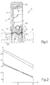
- a seal assembly is generally indicated 5, for insertion between two known relatively rotatable members, only the rotatable member, defined by a shaft indicated by a broken line in Figure 1, being shown, for the sake of simplicity.
- the seal assembly 5 can be mounted on a wheel hub of a motor vehicle, which is rotatable relative to a support arranged to the right of the seal assembly 5 in the drawing and not shown in Figure 1 for the sake of simplicity.
- the seal assembly 5 includes a substantially rigid annular frame 7, made of formed metal and shaped like an upturned L cross-section, having a cylindrical sleeve portion 8 and a flat flange portion 9. An elastomeric seal element 11 is secured to the annular frame 7 so as partially to cover it.
- the element 11, which was formed directly on the frame 7, preferably by compression forming, and glued to the frame 7 during vulcanization, includes a radial sealing lip 12 which projects from the frame 7 towards the shaft 6, on the opposite side to the sleeve portion 8.
- the lip 12 has a sealing surface 13 for slidably engaging, in use, a cylindrical sealing surface 14 of the shaft 6.
- the element 11 also includes a portion 15 which radially covers the outside of the sleeve portion 8, thereby forming a static seal with the respective seat of insertion of the seal assembly 5, and a portion 16 connecting the lip 12 to the portion 15, which adheres to the flange portion 9 of the frame 7.
- the lip 12 includes a main sealing lip 17, having a triangular (V-shaped) radial section and defining the sealing surface 13 between two faces 18 and 19 and an annular edge 21 facing the shaft 6.
- the lip 12 also includes a dust-shield lip 22 which is substantially rectangular in cross-section and has two sides inclined to the axis 26 of the shaft 6.
- the lip 22 has two surfaces 23 and 24 defining a second sealing edge 27 facing the shaft 6. The width of the two surfaces 23 and 24 is determined so that the dust-shield lip 22 is relatively resiliently compliant outwardly of the shaft 6.
- the sealing surface 13 of the lip 12 also includes a cylindrical portion 28, arranged on the side of the support of the shaft 6 (on the right in Figure 1) and, in addition to the two surfaces 18 and 19 of the main lip 17, the surface 23 of the dust-shield lip 22 faces the main lip 17.
- the seal assembly 5 includes resilient means (a toroidal spring) mounted externally on the lip 12 in order to increase, in use, the sliding pressure of the latter on the cylindrical surface 14 of the shaft 6, housed in particular in a groove 31 in the lip 12 opposite the sealing surface 13.
- resilient means a toroidal spring
- At least part of the surface 13, the entire surface 13 in the embodiment illustrated, is coated with a thin PTFE film 32, to a thickness of only a few hundredths of a millimetre and in any case no more than around 0.2mm, formed in situ on the lip 12 in the following manner.
- the seal assembly 5 as described is first assembled in a known manner, apart from the film 32, and the sealing element 11 is vulcanized.
- the film 32 is then formed in situ on the seal assembly thus produced, which is identical to prior art sliding seal assemblies, by first applying, in particular by spraying a thin layer of a polymerizable solution of PTFE precursors, monomers and/or olygomers and/or low molecular weight polymers for example, onto the sealing surface 13 (or onto the portion thereof on which the film 32 is required), to a thickness which is preferably less than 0.02mm, and then polymerizing the layer of solution in an oven or autoclave, for example, or even at ambient temperature. During polymerization, the layer of solution forms the film 32 which adheres mechanically and chemically to the rubber of the lip 12, coating the surface 13 and, above all, the sealing edge 21.
- an aqueous solution of polymerizable materials is used to form the film 32, by spraying it onto the surface 13 with suitable nozzles. It is advantageous to use the solution sold by the Dow Corning Corporation under the trade name "MOLYKOTE D-96.
- the steps of spraying and polymerization are preferably carried out so as to achieve a thin layer or film of PTFE, of a thickness of between 0.001 and 0.02mm.
- Polymerization may be carried out at a temperature of between 20°C and 50°C.
- the sealing lip 12 has a frictional couple of around half that of prior art sealing rings but, surprisingly, although the PTFE film is very thin, only a few microns, the sealing lip has a long life, wearing only very slowly. This is probably due to the fact that, as a result of this extreme thinness, in use the film 32 transfers part of its constituting PTFE to the shaft 6, thus forming a working counterface on the surface 14 for the sealing surface 13.
- Figure 2 shows a diagram of the frictional couple, expressed as N/m according to the operating time, comparing a Teflon-coated seal assembly according to the invention with an identical one made according to the prior art. The tests were conducted with a 64-mm diameter shaft, starting at ambient temperature and rotating at 3000 rpm for two hours.
- the two unbroken lines on the diagram show the frictional couple of the Teflon-coated seal assembly 5 as found in two separate trials, while the two broken lines show the frictional couple in the two respective tests of a known sealing ring.
- the average wear on the sealing edge 21 of the lip 12 was 0.21mm, while that on the sealing edge of the known device was 0.42mm.
- the PTFE layer or film 32 could be applied by a different method to spraying.
- the Teflon coating can be applied to any seal assembly and the shape of the main lip 17 and/or of the dust-shield lip 22 could be modified.
Landscapes
- Engineering & Computer Science (AREA)
- General Engineering & Computer Science (AREA)
- Mechanical Engineering (AREA)
- Sealing With Elastic Sealing Lips (AREA)
- Rolling Contact Bearings (AREA)
Applications Claiming Priority (2)
| Application Number | Priority Date | Filing Date | Title |
|---|---|---|---|
| IT1999TO001087A IT1311310B1 (it) | 1999-12-10 | 1999-12-10 | Complesso di tenuta a basso attrito, in particolare per cuscinetti dirotolamento, e procedimento per il suo ottenimento. |
| ITTO991087 | 1999-12-10 |
Publications (3)
| Publication Number | Publication Date |
|---|---|
| EP1106878A2 true EP1106878A2 (fr) | 2001-06-13 |
| EP1106878A4 EP1106878A4 (fr) | 2002-01-25 |
| EP1106878A3 EP1106878A3 (fr) | 2002-03-13 |
Family
ID=11418287
Family Applications (1)
| Application Number | Title | Priority Date | Filing Date |
|---|---|---|---|
| EP00127000A Withdrawn EP1106878A3 (fr) | 1999-12-10 | 2000-12-08 | Joint d'étanchéité à faible frottement, en particulier pour palier à roulement, et sa méthode de fabrication |
Country Status (2)
| Country | Link |
|---|---|
| EP (1) | EP1106878A3 (fr) |
| IT (1) | IT1311310B1 (fr) |
Cited By (7)
| Publication number | Priority date | Publication date | Assignee | Title |
|---|---|---|---|---|
| US6726212B2 (en) | 1997-09-25 | 2004-04-27 | Transcom, Inc. | Retrofittable severe duty seal for a shaft |
| US7108267B2 (en) | 2001-10-31 | 2006-09-19 | International Seal Company, Inc. | Seal for a shaft |
| US7658386B2 (en) | 1997-09-25 | 2010-02-09 | Freudenberg-Nok General Partnership | Retrofittable severe duty seal for a shaft |
| CN105240534A (zh) * | 2015-10-21 | 2016-01-13 | 宝塔实业股份有限公司 | 一种新型油封 |
| DE102016213821A1 (de) | 2015-07-27 | 2017-02-02 | Aktiebolaget Skf | Verfahren zum Anfertigen einer Beschichtung |
| CN106763789A (zh) * | 2017-01-13 | 2017-05-31 | 东莞市瑞拓五金橡塑有限公司 | 橡胶密封圈 |
| CN108426033A (zh) * | 2017-02-14 | 2018-08-21 | 舍弗勒技术股份两合公司 | 唇形密封件 |
Family Cites Families (4)
| Publication number | Priority date | Publication date | Assignee | Title |
|---|---|---|---|---|
| FR2713299B1 (fr) * | 1993-12-01 | 1996-02-16 | Joint Francais | Piston étanche et aérosol comportant un tel piston. |
| JP3807802B2 (ja) * | 1996-12-11 | 2006-08-09 | 株式会社ジェイテクト | リブ付オイルシール |
| JPH11325256A (ja) * | 1998-05-15 | 1999-11-26 | Koyo Seiko Co Ltd | オイルシール |
| IT1303577B1 (it) * | 1998-12-11 | 2000-11-14 | Skf Ind Spa | Dispositivo di tenuta per cuscinetti. |
-
1999
- 1999-12-10 IT IT1999TO001087A patent/IT1311310B1/it active
-
2000
- 2000-12-08 EP EP00127000A patent/EP1106878A3/fr not_active Withdrawn
Non-Patent Citations (1)
| Title |
|---|
| None |
Cited By (11)
| Publication number | Priority date | Publication date | Assignee | Title |
|---|---|---|---|---|
| US6726212B2 (en) | 1997-09-25 | 2004-04-27 | Transcom, Inc. | Retrofittable severe duty seal for a shaft |
| US6991234B2 (en) | 1997-09-25 | 2006-01-31 | International Seal Company, Inc. | Retrofittable severe duty seal for a shaft |
| US7159871B2 (en) | 1997-09-25 | 2007-01-09 | Freudenberg-Nok General Partnership | Retrofittable severe duty seal for a shaft |
| US7658386B2 (en) | 1997-09-25 | 2010-02-09 | Freudenberg-Nok General Partnership | Retrofittable severe duty seal for a shaft |
| US7108267B2 (en) | 2001-10-31 | 2006-09-19 | International Seal Company, Inc. | Seal for a shaft |
| DE102016213821A1 (de) | 2015-07-27 | 2017-02-02 | Aktiebolaget Skf | Verfahren zum Anfertigen einer Beschichtung |
| US10377917B2 (en) | 2015-07-27 | 2019-08-13 | Aktiebolaget Skf | Process for preparing a coating |
| CN105240534A (zh) * | 2015-10-21 | 2016-01-13 | 宝塔实业股份有限公司 | 一种新型油封 |
| CN106763789A (zh) * | 2017-01-13 | 2017-05-31 | 东莞市瑞拓五金橡塑有限公司 | 橡胶密封圈 |
| CN108426033A (zh) * | 2017-02-14 | 2018-08-21 | 舍弗勒技术股份两合公司 | 唇形密封件 |
| WO2018149274A1 (fr) * | 2017-02-14 | 2018-08-23 | 舍弗勒技术股份两合公司 | Joint à lèvre |
Also Published As
| Publication number | Publication date |
|---|---|
| ITTO991087A1 (it) | 2001-06-10 |
| EP1106878A3 (fr) | 2002-03-13 |
| ITTO991087A0 (it) | 1999-12-10 |
| IT1311310B1 (it) | 2002-03-12 |
| EP1106878A4 (fr) | 2002-01-25 |
Similar Documents
| Publication | Publication Date | Title |
|---|---|---|
| US5183271A (en) | Sealing device and manufacturing method of the same | |
| US6182975B1 (en) | Sealing device having an annular space between sealing lips | |
| CN101208548B (zh) | 动态密封件、旋转密封件及制造高温动态密封件的方法 | |
| US9163730B2 (en) | Unitized radial fluid seal | |
| US5595697A (en) | Method of manufacturing a sealing device | |
| CA2341909C (fr) | Joint d'etancheite composite a double module d'elasticite et son procede de fabrication | |
| WO2005026588A1 (fr) | Dispositif d'etancheite pour arbre a mouvement alternatif | |
| US3995868A (en) | Polytetrafluoroethylene lip seal | |
| EP0886087B1 (fr) | Joint à lèvre radiale | |
| SE509598C2 (sv) | Radialläpptätning | |
| US6666459B1 (en) | Radial shaft seal | |
| AU735430B2 (en) | Cassette seal with radial and axial lip | |
| HU222365B1 (hu) | Tömítőgyűrű | |
| KR101239771B1 (ko) | 오일시일 및 그 제조방법 | |
| EP1106878A2 (fr) | Joint d'étanchéité à faible frottement, en particulier pour palier à roulement, et sa méthode de fabrication | |
| JP2005121164A (ja) | シール装置 | |
| US4502698A (en) | Rotary face seal with flexible annular boot | |
| US20120153573A1 (en) | Fluid Seal Assembly | |
| JPH11236977A (ja) | 回転軸シール | |
| JPH09133217A (ja) | リップ型シール | |
| CN102821989B (zh) | 一种密封系统的装置和方法 | |
| EP1888950B1 (fr) | Joint d'etancheite et son procede de fabrication | |
| JP3830604B2 (ja) | 密封装置の製造方法 | |
| EP1669619B1 (fr) | Moyen d'étanchéité pour un palier de moyeu d'une roue | |
| JP3785809B2 (ja) | 密封装置 |
Legal Events
| Date | Code | Title | Description |
|---|---|---|---|
| PUAI | Public reference made under article 153(3) epc to a published international application that has entered the european phase |
Free format text: ORIGINAL CODE: 0009012 |
|
| AK | Designated contracting states |
Kind code of ref document: A2 Designated state(s): DE ES FR GB IT SE Kind code of ref document: A2 Designated state(s): AT BE CH CY DE DK ES FI FR GB GR IE IT LI LU MC NL PT SE TR |
|
| AX | Request for extension of the european patent |
Free format text: AL;LT;LV;MK;RO;SI |
|
| PUAL | Search report despatched |
Free format text: ORIGINAL CODE: 0009013 |
|
| AK | Designated contracting states |
Kind code of ref document: A3 Designated state(s): AT BE CH CY DE DK ES FI FR GB GR IE IT LI LU MC NL PT SE TR |
|
| AX | Request for extension of the european patent |
Free format text: AL;LT;LV;MK;RO;SI |
|
| 17P | Request for examination filed |
Effective date: 20020912 |
|
| AKX | Designation fees paid |
Free format text: DE ES FR GB IT SE |
|
| 17Q | First examination report despatched |
Effective date: 20030306 |
|
| STAA | Information on the status of an ep patent application or granted ep patent |
Free format text: STATUS: THE APPLICATION IS DEEMED TO BE WITHDRAWN |
|
| 18D | Application deemed to be withdrawn |
Effective date: 20050503 |