EP1106899A2 - Elément de conduite avec une surface d'accouplement pour la connexion à un autre élément de conduite - Google Patents
Elément de conduite avec une surface d'accouplement pour la connexion à un autre élément de conduite Download PDFInfo
- Publication number
- EP1106899A2 EP1106899A2 EP00126130A EP00126130A EP1106899A2 EP 1106899 A2 EP1106899 A2 EP 1106899A2 EP 00126130 A EP00126130 A EP 00126130A EP 00126130 A EP00126130 A EP 00126130A EP 1106899 A2 EP1106899 A2 EP 1106899A2
- Authority
- EP
- European Patent Office
- Prior art keywords
- base body
- pipe element
- element according
- pipe
- connection
- Prior art date
- Legal status (The legal status is an assumption and is not a legal conclusion. Google has not performed a legal analysis and makes no representation as to the accuracy of the status listed.)
- Granted
Links
- 230000008878 coupling Effects 0.000 title description 2
- 238000010168 coupling process Methods 0.000 title description 2
- 238000005859 coupling reaction Methods 0.000 title description 2
- 238000007789 sealing Methods 0.000 claims abstract description 84
- 239000000463 material Substances 0.000 claims abstract description 41
- 239000004033 plastic Substances 0.000 claims description 49
- 229920003023 plastic Polymers 0.000 claims description 49
- 239000002184 metal Substances 0.000 claims description 31
- 238000003825 pressing Methods 0.000 claims description 7
- 230000006835 compression Effects 0.000 claims description 5
- 238000007906 compression Methods 0.000 claims description 5
- 238000002347 injection Methods 0.000 claims description 4
- 239000007924 injection Substances 0.000 claims description 4
- 229910001092 metal group alloy Inorganic materials 0.000 claims description 4
- 229920000491 Polyphenylsulfone Polymers 0.000 claims description 3
- 239000013013 elastic material Substances 0.000 claims description 3
- 229920002492 poly(sulfone) Polymers 0.000 claims description 3
- 229920000122 acrylonitrile butadiene styrene Polymers 0.000 claims description 2
- 238000010276 construction Methods 0.000 claims description 2
- 210000001061 forehead Anatomy 0.000 claims description 2
- 239000007788 liquid Substances 0.000 claims description 2
- 239000002905 metal composite material Substances 0.000 claims description 2
- 229920003229 poly(methyl methacrylate) Polymers 0.000 claims description 2
- 239000004926 polymethyl methacrylate Substances 0.000 claims description 2
- 238000001746 injection moulding Methods 0.000 claims 2
- 230000004308 accommodation Effects 0.000 abstract 1
- 238000011161 development Methods 0.000 description 3
- 230000018109 developmental process Effects 0.000 description 3
- 229920000642 polymer Polymers 0.000 description 3
- 239000003566 sealing material Substances 0.000 description 3
- 230000007704 transition Effects 0.000 description 3
- -1 Polypropylen Polymers 0.000 description 2
- 229920001155 polypropylene Polymers 0.000 description 2
- 230000036316 preload Effects 0.000 description 2
- 101100390736 Danio rerio fign gene Proteins 0.000 description 1
- 241000446313 Lamella Species 0.000 description 1
- 101100390738 Mus musculus Fign gene Proteins 0.000 description 1
- 239000004743 Polypropylene Substances 0.000 description 1
- 229920001871 amorphous plastic Polymers 0.000 description 1
- 238000005452 bending Methods 0.000 description 1
- 230000015572 biosynthetic process Effects 0.000 description 1
- 239000002178 crystalline material Substances 0.000 description 1
- 230000000694 effects Effects 0.000 description 1
- 238000005516 engineering process Methods 0.000 description 1
- 238000001125 extrusion Methods 0.000 description 1
- 238000010438 heat treatment Methods 0.000 description 1
- 238000009434 installation Methods 0.000 description 1
- 238000004519 manufacturing process Methods 0.000 description 1
- 239000000155 melt Substances 0.000 description 1
- 238000000034 method Methods 0.000 description 1
- 229920001169 thermoplastic Polymers 0.000 description 1
- 239000004416 thermosoftening plastic Substances 0.000 description 1
Images


Classifications
-
- F—MECHANICAL ENGINEERING; LIGHTING; HEATING; WEAPONS; BLASTING
- F16—ENGINEERING ELEMENTS AND UNITS; GENERAL MEASURES FOR PRODUCING AND MAINTAINING EFFECTIVE FUNCTIONING OF MACHINES OR INSTALLATIONS; THERMAL INSULATION IN GENERAL
- F16L—PIPES; JOINTS OR FITTINGS FOR PIPES; SUPPORTS FOR PIPES, CABLES OR PROTECTIVE TUBING; MEANS FOR THERMAL INSULATION IN GENERAL
- F16L47/00—Connecting arrangements or other fittings specially adapted to be made of plastics or to be used with pipes made of plastics
- F16L47/20—Connecting arrangements or other fittings specially adapted to be made of plastics or to be used with pipes made of plastics based principally on specific properties of plastics
- F16L47/24—Connecting arrangements or other fittings specially adapted to be made of plastics or to be used with pipes made of plastics based principally on specific properties of plastics for joints between metal and plastics pipes
Definitions
- the invention relates to a pipe element with a connection surface, by means of which the pipe element is in contact with another pipe element, in particular a pipe element of another pipe system lets connect.
- the invention is concerned with the design of pipeline elements with a plastic base body and one supporting the connection surface Insert or connection body made of a plastic material of the Basic body of different material, which is in particular a Metal or a metal alloy.
- DE 26 26 302 A1 describes a pipe element with a connection surface for connecting to another pipe element with a base body made of a plastic material and a connector body made of one material other than that of the base body is known.
- the connector body the connection area for the connection to another Pipe element on.
- the connector body and the base body point Interfaces along which both lie against each other.
- At least one the interfaces of the connector body and base body have at least a receiving groove, at least one sealing element in the receiving groove is arranged from an elastic material.
- the invention has for its object such a pipe element to improve that leakage along the touching Boundaries between base body and connection body reliably avoided becomes.
- a first sealing element which consists of a compressible Material is and / or compressible due to its construction is and is arranged with bias in a receiving groove, which is preferably is formed in the connector body, but just as well in be arranged in the base body and / or over the base body and connection body can extend.
- At least one such receiving groove is in the area of at least one interface between the connector body and the base body intended.
- One or each receiving groove can also several sealing elements can be included. Because of its preload presses the first sealing element against the connector body as well against the body.
- the invention Pipe element either the first or the second sealing element type or at least two different types of sealing elements.
- the first Sealing element (hereinafter referred to simply as “the sealing element” for the sake of simplicity) referred to) as a (band) ring element with a radially inner and a radially outer contact surface for contacting the interfaces of connecting body and base body.
- the foreheads of the first sealing element are preferably rounded, the The radius of these curves is larger than the radius between the flanks and the bottom of the receiving groove receiving the first sealing element.
- the sealing element can have an embedded stiffening element (core), to give the sealing element greater mechanical stability. This is advantageous in terms of the sealing function.
- core embedded stiffening element
- the sealing element protruding from one of its contact surfaces, particularly in cross-section triangular ribs with intervening also in particular triangular grooves.
- This rib / groove design is special formed in the central region of the contact surface of the sealing element and increases compressibility because there is less sealing material is.
- the sealing element thus deforms in its central region Direction to the part (basic body or connecting body) on which the contact surface provided with the ribs and grooves rests. According to Art contact surface formed by sealing lamella nestles against the concerned body and thus seals more reliably.
- the sealing element preferably has a smaller one in the axial end regions Compressibility on what is either constructive or material-related or a combination of both.
- these are Front ends of the sealing element with a larger radius of curvature than that Rounding radius between the flanks and the bottom of the sealing element Providing receiving groove. This happens, as already mentioned above, for increased surface pressure, what the sealing function of the sealing element improved.
- the connector body is expedient against axial and rotary Force anchored securely to the body.
- the interface between the two bodies is non-positive.
- This frictional connection can be made cohesively, for example, by the interfaces are welded or glued together.
- An alternative for this purpose forms the frictional connection, in which the base body and the Connection bodies are interconnected by a press fit.
- a last alternative for a non-positive connection of connection bodies and base body consists of a positive connection of both, by having both interfaces with one another that correspond in their shape and interlock Projections and depressions are provided.
- connection body not only on the outside or only on the inside is in contact with the material of the base body, but that the Base body the connector body on two opposite Pages at least partially included. These two sides of the connector body are provided with projections or depressions in the corresponding Engage protrusions or depressions in the base body. In this respect, the connection body is thus on the opposite side from the base body Sides held form-fitting.
- connection body which is designed, for example, as a sleeve with an internal thread has protrusions on its outside, which as a circumferential Ribs are formed and spaced apart on the whole Are arranged distributed outside.
- Such a connector body has then preferably also in the region of its one axial end on the inside at least one protrusion or depression, so that too in this section of the inside of the connector body it becomes one Form-fit and thus to encompass the connector body on both sides comes through the material of the base body.
- Such a trained one The connector body is reliably secured against axial forces on the base body held.
- connection surface is the connection body in particular provided with a thread.
- Threads are nowadays preferably used to the pipe elements of different systems to be able to connect with each other. But also other options the coupling of the pipe elements of different systems conceivable, such as bayonet locks, welded connections or Press connections.
- the threaded connection has the advantage that if it is made of metal, as a self-sealing threaded connection DVGW approved (and specifically if a cylindrical / conical Thread pairing is provided). On special sealing elements in the threaded connection area can therefore be dispensed with.
- the sealing element is in the inventive Pipe element in a prestressed state and lies with a minimum contact pressure both on the connector body and on the body.
- the pipe element according to the invention can be preferably realized as an extrusion plastic part
- the base body consists of a plastic material that around or on the connector body is injected.
- the connector body together with the sealing element inserted into the injection mold and the plastic material around or injected onto the connector body.
- the filling or post-pressure can now of the liquid plastic material to generate the preload of the sealing element can be used.
- the pressure under which that Plastic material is in the injection mold while it is hardening thus compresses the sealing element, whereby this the required pressing force to the sealing system both on the base body and on can produce the connector body.
- the pipe element according to the invention has in particular one Base body made of a high temperature resistant plastic material, especially made of PSU, PPSU, PMMA, ABS, PS, PC, while the connector body preferably made of a metal or a metal alloy or a plastic material.
- a pipe element then serves, for example, as a transition piece from a plastic system to a metal system in which a metal pipe element with the Connection body also made of metal can be coupled.
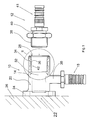
- Fig. 1 shows two pipe elements 10, 12, which are designed as press fittings are and belong to different pipe systems. That's how it works the pipe element 10 is a plastic fitting with a Plastic base body 14, which is designed as an angle tube element. On the base body 14 is a support sleeve 18 made of plastic, on the a plastic pipe or plastic-metal composite pipe can be pressed on.
- the base body 14 has a pipe section 20, of which the support body 18 projects radially and is closed at one end 22. At this end 22, the pipe section 20 has a flange 24 with which the pipe section 20 and thus the entire pipe element 10 can be fastened to a wall 26 is.
- the opposite end 28 of the closed end 28 of the Pipe section 20 is open and serves to accommodate the fitting pipe element 12.
- a metal connector body 34 is used, which has an internal thread 36, with which the external thread 38 on the fitting body 40 of the fitting pipe element 12 is screwable.
- the fitting body 40 has one Support sleeve 41 on which a tube can be pressed.
- connection surface 42 for connection of the metal fitting pipe element 12 forms.
- connection surface 42 is designed as an internal thread 36, which then cooperates with the external thread 38 of the fitting pipe element 12.
- the metal connector body 34 is arranged on the outside of the pipe element 10 and then a Has an external thread that has an internal thread with the pipe element 10 screwable pipe element is provided.
- a high-temperature resistant material comes as the material for the base body 14 amorphous plastic, such as PSU or PPSU in question, the DVGW is allowed.
- the metal connector body 34 and the Fitting pipe element 12 made of a metal or metal alloy, the or which is also approved according to DVGW.
- both bodies 14.34 lie along interfaces 44.46 to each other.
- the Metal connector body 34 In the interface 46 of the metal connection body 34 are a plurality of circumferential grooves 48 incorporated into the Engage projections 50 of the base body 14.
- the Metal connector body 34 a further external (receiving) groove 52 in which there is an annular sealing element 54.
- the sealing element 54 consists of a sealing material that has a lower modulus of elasticity has as the plastic material of the base body 14.
- the sealing element 54 is designed in the manner of a band ring and has an internal one Contact surface 56 and an external contact surface 58. The inside The contact surface 56 lies on the base 60 of the receiving groove 52 on, while the outer contact surface 58 at the interface 44 of the Base body 14 abuts.
- the sealing element lies on the axial ends 62 54 on the flanks 64 of the receiving groove 52.
- the sealing element 54 is under prestress and presses with it a certain pressing force on its contact surfaces 56,58 against the Metal connector body 34 or the base body 14. By the bias the contact surfaces 56, 58 of the sealing element 54 remain on the interfaces 44,46 in plant if there is between the interfaces in the Over time, if only on a microscopic scale, detachments Set (capillary). So that is the connection between the base body 14 made of plastic and the connector body 34 made of metal over the entire Operating time of the pipe element 10 media-tight.
- a second sealing element 68 the consists of a sealing material that expands upon contact with moisture.
- This second sealing element 68 secures the boundary layer between the Base body 14 and the metal connector body 34 in the case that for whatever reason, the sealing element 54 does not seal completely should (additional sealing security).
- the inner axial end 66 of the substantially sleeve-shaped connecting body 34 both on the Enclosed on the outside as well as on the inside by the material of the base body 14. Both on the outside and on the inside the Metal connector body 34 protrusions 69, the protrusion 69 on the inside is encompassed by a projection 70 of the base body 14.
- the interface 46 is its interface 46 on the one hand from the outside as well as from the inside of the Connection body 34 formed. The interface becomes the same in this area 44 of the base body 14 from its radially inward direction Surface section and the surface section in the region of the projection 70 educated.
- Fig. 3 and 4 show alternative configurations of sealing elements 54 ', 54 ".
- the sealing element 54' has on its radially inner side Contact surface 56 a toothing in the form of V-shaped ribs 72 with intermediate V-shaped grooves 74.
- the sealing element 54 ' with a stiffening core 76 made in particular of metal.
- the sealing element 54 ' has a radius of curvature which is larger than the radius of curvature in the corner region 78 between the flanks 64 and the base 60 of the receiving groove 52 in the metal connection body 34.
- the sealing element 54 ' On the outer contact side 58 facing the base body 14 the sealing element 54 'has a toothing with flat projections 80 and further protrusions 82,84. These two the latter projections 82, 84 serve to reinforce the system of the Sealing element 54 'both on the base body 14 and in the receiving groove 52 of the connecting body 34.
- the pipeline element 10 by overmolding the connector body 34 the plastic material of the base body 14 is produced.
- the flow direction the plastic melt is indicated in Fig. 3 with the arrow 86. It can be seen that the projections 82, 84 in the direction of the arrow 86 Project inclined from the contact surface 58 of the sealing element 54 '.
- FIG. 4 shows a variant of the sealing element 54 'of FIG. 3.
- the sealing element 4 "of FIG. 4 has symmetrical arrangements about a central plane 88, mutually pointing oblique projections 82 ", 84" on, which is symmetrical to a plastic melt filling point (indicated at 90) are arranged over which the plastic melt along the arrows 92 flows along the contact surface 58 of the sealing element 54 ".
- a plastic melt filling point indicated at 90
Landscapes
- Engineering & Computer Science (AREA)
- General Engineering & Computer Science (AREA)
- Mechanical Engineering (AREA)
- Quick-Acting Or Multi-Walled Pipe Joints (AREA)
- Joints With Sleeves (AREA)
- Branch Pipes, Bends, And The Like (AREA)
- Gasket Seals (AREA)
Applications Claiming Priority (2)
| Application Number | Priority Date | Filing Date | Title |
|---|---|---|---|
| DE19957601A DE19957601C2 (de) | 1999-11-30 | 1999-11-30 | Rohrleitungselement mit einer Anschlussfläche zum Verbinden mit einem anderen Rohrleitungselement |
| DE19957601 | 1999-11-30 |
Publications (3)
| Publication Number | Publication Date |
|---|---|
| EP1106899A2 true EP1106899A2 (fr) | 2001-06-13 |
| EP1106899A3 EP1106899A3 (fr) | 2003-06-04 |
| EP1106899B1 EP1106899B1 (fr) | 2005-10-26 |
Family
ID=7930859
Family Applications (1)
| Application Number | Title | Priority Date | Filing Date |
|---|---|---|---|
| EP00126130A Expired - Lifetime EP1106899B1 (fr) | 1999-11-30 | 2000-11-30 | Elément de conduite avec une surface d'accouplement pour la connexion à un autre élément de conduite |
Country Status (4)
| Country | Link |
|---|---|
| EP (1) | EP1106899B1 (fr) |
| AT (1) | ATE308011T1 (fr) |
| DE (2) | DE19957601C2 (fr) |
| ES (1) | ES2248006T3 (fr) |
Cited By (1)
| Publication number | Priority date | Publication date | Assignee | Title |
|---|---|---|---|---|
| FR2930313A1 (fr) * | 2008-04-21 | 2009-10-23 | Hutchinson Sa | Dispositif de raccordement, son procede d'assemblage et circuit de climatisation ou de direction assistee l'incorporant. |
Families Citing this family (2)
| Publication number | Priority date | Publication date | Assignee | Title |
|---|---|---|---|---|
| DE102006051774A1 (de) | 2006-11-03 | 2008-05-08 | Uponor Innovation Ab | Fitting für ein Rohr |
| DE202007011565U1 (de) * | 2007-08-17 | 2009-01-02 | Rehau Ag + Co | Rohranordnung |
Family Cites Families (5)
| Publication number | Priority date | Publication date | Assignee | Title |
|---|---|---|---|---|
| JPS51160216U (fr) * | 1975-06-14 | 1976-12-20 | ||
| DE8406562U1 (de) * | 1984-03-02 | 1984-08-30 | Jeschke, Immanuel, 3203 Sarstedt | Uebergangsstueck in einer gasleitung |
| DE8800282U1 (de) * | 1988-01-13 | 1988-02-25 | Manibs Spezialarmaturen GmbH & Co KG, 5630 Remscheid | Übergangskupplung zwischen einem Kunststoff- und Metallrohr, insbesondere in Gasleitungen |
| US5172919A (en) * | 1990-02-22 | 1992-12-22 | C. I. Kasei Co., Ltd. | Appliance for preventing water from leaking through joint |
| GB2273537B (en) * | 1992-12-17 | 1996-01-31 | Yong Goo Shin | Ring packing |
-
1999
- 1999-11-30 DE DE19957601A patent/DE19957601C2/de not_active Expired - Fee Related
-
2000
- 2000-11-30 AT AT00126130T patent/ATE308011T1/de not_active IP Right Cessation
- 2000-11-30 EP EP00126130A patent/EP1106899B1/fr not_active Expired - Lifetime
- 2000-11-30 DE DE50011430T patent/DE50011430D1/de not_active Expired - Lifetime
- 2000-11-30 ES ES00126130T patent/ES2248006T3/es not_active Expired - Lifetime
Non-Patent Citations (1)
| Title |
|---|
| None |
Cited By (2)
| Publication number | Priority date | Publication date | Assignee | Title |
|---|---|---|---|---|
| FR2930313A1 (fr) * | 2008-04-21 | 2009-10-23 | Hutchinson Sa | Dispositif de raccordement, son procede d'assemblage et circuit de climatisation ou de direction assistee l'incorporant. |
| EP2112417A1 (fr) | 2008-04-21 | 2009-10-28 | Hutchinson | Dispositif de raccordement |
Also Published As
| Publication number | Publication date |
|---|---|
| ATE308011T1 (de) | 2005-11-15 |
| EP1106899A3 (fr) | 2003-06-04 |
| EP1106899B1 (fr) | 2005-10-26 |
| DE50011430D1 (de) | 2005-12-01 |
| ES2248006T3 (es) | 2006-03-16 |
| DE19957601A1 (de) | 2001-06-07 |
| DE19957601C2 (de) | 2001-09-13 |
Similar Documents
| Publication | Publication Date | Title |
|---|---|---|
| EP1391640B1 (fr) | Bague d'étanchéité | |
| DE2724793A1 (de) | Dichtungsvorrichtung | |
| DE102017118162A1 (de) | Anschlussvorrichtung für Rohrleitungen mit Leckageanzeige | |
| EP0848200B1 (fr) | Raccord de serrage pour tuyaux | |
| EP1881251B1 (fr) | Bague d'étanchéité et dispositif de liaison pour un raccord à manchon | |
| DE2024840A1 (de) | Abdichtungskonstruktion für Rohrverbindungen | |
| EP2404097B1 (fr) | Système de raccord pour le raccord d'un tuyau à un tuyau principal | |
| DE10252141A1 (de) | Flachdichtungsring | |
| EP2530363A1 (fr) | Joint et boîtier doté de celui-ci | |
| EP1389691A1 (fr) | Ecrou en plastique pour monter à un élément de construction | |
| EP1106899B1 (fr) | Elément de conduite avec une surface d'accouplement pour la connexion à un autre élément de conduite | |
| DE102014108108B4 (de) | Gasdichtungsmechanismus mit einem Dichtungskörper | |
| DE29980147U1 (de) | Verbindungs- und Anschlußstück für Wellrohre | |
| EP0565957B1 (fr) | Pièce de connexion pour un conduit | |
| DE102022110061A1 (de) | Verwendung einer Leitungsdurchführung | |
| DE102018109998A1 (de) | Rohranschlusssystem und Verfahren zur Herstellung eines Rohranschlusses | |
| DE19946133A1 (de) | Lippendichtring | |
| DE10047758A1 (de) | Einsatz für eine Öffnung in einem insbesondere rohrförmigen Hohlkörper | |
| DE202012004630U1 (de) | Betonrohr mit aus Kunststoff bestehender Außenauskleidung | |
| DE4441348A1 (de) | Flanschverbindung | |
| DE19943473B4 (de) | Dichtungsvorrichtung | |
| EP4317749B1 (fr) | Ensemble joint et appareil de traitement d'eau comprenant l'ensemble joint | |
| EP0347608B1 (fr) | Joint d'étanchéité | |
| DE102004063973A1 (de) | Dichtungsbaugruppe für ein Ventil | |
| DE10128440A1 (de) | Dichtungselement und Dichtungsanordnung mit geringer Leckrate |
Legal Events
| Date | Code | Title | Description |
|---|---|---|---|
| PUAI | Public reference made under article 153(3) epc to a published international application that has entered the european phase |
Free format text: ORIGINAL CODE: 0009012 |
|
| AK | Designated contracting states |
Kind code of ref document: A2 Designated state(s): AT BE CH CY DE DK ES FI FR GB GR IE IT LI LU MC NL PT SE TR |
|
| AX | Request for extension of the european patent |
Free format text: AL;LT;LV;MK;RO;SI |
|
| RAP1 | Party data changed (applicant data changed or rights of an application transferred) |
Owner name: UPONOR INNOVATION AB |
|
| PUAL | Search report despatched |
Free format text: ORIGINAL CODE: 0009013 |
|
| AK | Designated contracting states |
Designated state(s): AT BE CH CY DE DK ES FI FR GB GR IE IT LI LU MC NL PT SE TR |
|
| AX | Request for extension of the european patent |
Extension state: AL LT LV MK RO SI |
|
| 17P | Request for examination filed |
Effective date: 20030919 |
|
| AKX | Designation fees paid |
Designated state(s): AT BE CH CY DE DK ES FI FR GB GR IE IT LI LU MC NL PT SE TR |
|
| 17Q | First examination report despatched |
Effective date: 20040211 |
|
| GRAP | Despatch of communication of intention to grant a patent |
Free format text: ORIGINAL CODE: EPIDOSNIGR1 |
|
| GRAS | Grant fee paid |
Free format text: ORIGINAL CODE: EPIDOSNIGR3 |
|
| GRAA | (expected) grant |
Free format text: ORIGINAL CODE: 0009210 |
|
| AK | Designated contracting states |
Kind code of ref document: B1 Designated state(s): AT BE CH CY DE DK ES FI FR GB GR IE IT LI LU MC NL PT SE TR |
|
| PG25 | Lapsed in a contracting state [announced via postgrant information from national office to epo] |
Ref country code: NL Free format text: LAPSE BECAUSE OF FAILURE TO SUBMIT A TRANSLATION OF THE DESCRIPTION OR TO PAY THE FEE WITHIN THE PRESCRIBED TIME-LIMIT Effective date: 20051026 Ref country code: TR Free format text: LAPSE BECAUSE OF FAILURE TO SUBMIT A TRANSLATION OF THE DESCRIPTION OR TO PAY THE FEE WITHIN THE PRESCRIBED TIME-LIMIT Effective date: 20051026 Ref country code: FI Free format text: LAPSE BECAUSE OF FAILURE TO SUBMIT A TRANSLATION OF THE DESCRIPTION OR TO PAY THE FEE WITHIN THE PRESCRIBED TIME-LIMIT Effective date: 20051026 Ref country code: IE Free format text: LAPSE BECAUSE OF FAILURE TO SUBMIT A TRANSLATION OF THE DESCRIPTION OR TO PAY THE FEE WITHIN THE PRESCRIBED TIME-LIMIT Effective date: 20051026 |
|
| REG | Reference to a national code |
Ref country code: GB Ref legal event code: FG4D Free format text: NOT ENGLISH |
|
| REG | Reference to a national code |
Ref country code: CH Ref legal event code: EP |
|
| PGFP | Annual fee paid to national office [announced via postgrant information from national office to epo] |
Ref country code: FR Payment date: 20051110 Year of fee payment: 6 |
|
| PG25 | Lapsed in a contracting state [announced via postgrant information from national office to epo] |
Ref country code: CY Free format text: LAPSE BECAUSE OF FAILURE TO SUBMIT A TRANSLATION OF THE DESCRIPTION OR TO PAY THE FEE WITHIN THE PRESCRIBED TIME-LIMIT Effective date: 20051130 Ref country code: AT Free format text: LAPSE BECAUSE OF NON-PAYMENT OF DUE FEES Effective date: 20051130 Ref country code: BE Free format text: LAPSE BECAUSE OF NON-PAYMENT OF DUE FEES Effective date: 20051130 Ref country code: LI Free format text: LAPSE BECAUSE OF NON-PAYMENT OF DUE FEES Effective date: 20051130 Ref country code: CH Free format text: LAPSE BECAUSE OF NON-PAYMENT OF DUE FEES Effective date: 20051130 Ref country code: MC Free format text: LAPSE BECAUSE OF NON-PAYMENT OF DUE FEES Effective date: 20051130 |
|
| REG | Reference to a national code |
Ref country code: IE Ref legal event code: FG4D Free format text: LANGUAGE OF EP DOCUMENT: GERMAN |
|
| REF | Corresponds to: |
Ref document number: 50011430 Country of ref document: DE Date of ref document: 20051201 Kind code of ref document: P |
|
| PG25 | Lapsed in a contracting state [announced via postgrant information from national office to epo] |
Ref country code: LU Free format text: LAPSE BECAUSE OF NON-PAYMENT OF DUE FEES Effective date: 20051226 |
|
| PG25 | Lapsed in a contracting state [announced via postgrant information from national office to epo] |
Ref country code: DK Free format text: LAPSE BECAUSE OF FAILURE TO SUBMIT A TRANSLATION OF THE DESCRIPTION OR TO PAY THE FEE WITHIN THE PRESCRIBED TIME-LIMIT Effective date: 20060126 Ref country code: GR Free format text: LAPSE BECAUSE OF FAILURE TO SUBMIT A TRANSLATION OF THE DESCRIPTION OR TO PAY THE FEE WITHIN THE PRESCRIBED TIME-LIMIT Effective date: 20060126 |
|
| REG | Reference to a national code |
Ref country code: SE Ref legal event code: TRGR |
|
| GBT | Gb: translation of ep patent filed (gb section 77(6)(a)/1977) |
Effective date: 20060213 |
|
| REG | Reference to a national code |
Ref country code: ES Ref legal event code: FG2A Ref document number: 2248006 Country of ref document: ES Kind code of ref document: T3 |
|
| PG25 | Lapsed in a contracting state [announced via postgrant information from national office to epo] |
Ref country code: PT Free format text: LAPSE BECAUSE OF FAILURE TO SUBMIT A TRANSLATION OF THE DESCRIPTION OR TO PAY THE FEE WITHIN THE PRESCRIBED TIME-LIMIT Effective date: 20060327 |
|
| NLV1 | Nl: lapsed or annulled due to failure to fulfill the requirements of art. 29p and 29m of the patents act | ||
| REG | Reference to a national code |
Ref country code: IE Ref legal event code: FD4D |
|
| REG | Reference to a national code |
Ref country code: CH Ref legal event code: PL |
|
| PLBE | No opposition filed within time limit |
Free format text: ORIGINAL CODE: 0009261 |
|
| STAA | Information on the status of an ep patent application or granted ep patent |
Free format text: STATUS: NO OPPOSITION FILED WITHIN TIME LIMIT |
|
| 26N | No opposition filed |
Effective date: 20060727 |
|
| EN | Fr: translation not filed | ||
| PG25 | Lapsed in a contracting state [announced via postgrant information from national office to epo] |
Ref country code: FR Free format text: LAPSE BECAUSE OF FAILURE TO SUBMIT A TRANSLATION OF THE DESCRIPTION OR TO PAY THE FEE WITHIN THE PRESCRIBED TIME-LIMIT Effective date: 20061215 |
|
| BERE | Be: lapsed |
Owner name: UPONOR INNOVATION A.B. Effective date: 20051130 |
|
| PGFP | Annual fee paid to national office [announced via postgrant information from national office to epo] |
Ref country code: DE Payment date: 20121121 Year of fee payment: 13 |
|
| PGFP | Annual fee paid to national office [announced via postgrant information from national office to epo] |
Ref country code: SE Payment date: 20121120 Year of fee payment: 13 Ref country code: IT Payment date: 20121128 Year of fee payment: 13 Ref country code: GB Payment date: 20121120 Year of fee payment: 13 Ref country code: ES Payment date: 20121122 Year of fee payment: 13 |
|
| GBPC | Gb: european patent ceased through non-payment of renewal fee |
Effective date: 20131130 |
|
| REG | Reference to a national code |
Ref country code: SE Ref legal event code: EUG |
|
| REG | Reference to a national code |
Ref country code: DE Ref legal event code: R119 Ref document number: 50011430 Country of ref document: DE Effective date: 20140603 |
|
| PG25 | Lapsed in a contracting state [announced via postgrant information from national office to epo] |
Ref country code: DE Free format text: LAPSE BECAUSE OF NON-PAYMENT OF DUE FEES Effective date: 20140603 Ref country code: SE Free format text: LAPSE BECAUSE OF NON-PAYMENT OF DUE FEES Effective date: 20131201 Ref country code: IT Free format text: LAPSE BECAUSE OF NON-PAYMENT OF DUE FEES Effective date: 20131130 |
|
| PG25 | Lapsed in a contracting state [announced via postgrant information from national office to epo] |
Ref country code: GB Free format text: LAPSE BECAUSE OF NON-PAYMENT OF DUE FEES Effective date: 20131130 |
|
| REG | Reference to a national code |
Ref country code: ES Ref legal event code: FD2A Effective date: 20150407 |
|
| PG25 | Lapsed in a contracting state [announced via postgrant information from national office to epo] |
Ref country code: ES Free format text: LAPSE BECAUSE OF NON-PAYMENT OF DUE FEES Effective date: 20131201 |