EP1106909A2 - Ensemble projecteur pour véhicules - Google Patents
Ensemble projecteur pour véhicules Download PDFInfo
- Publication number
- EP1106909A2 EP1106909A2 EP00126735A EP00126735A EP1106909A2 EP 1106909 A2 EP1106909 A2 EP 1106909A2 EP 00126735 A EP00126735 A EP 00126735A EP 00126735 A EP00126735 A EP 00126735A EP 1106909 A2 EP1106909 A2 EP 1106909A2
- Authority
- EP
- European Patent Office
- Prior art keywords
- light
- decoupling element
- housing
- headlight unit
- unit according
- Prior art date
- Legal status (The legal status is an assumption and is not a legal conclusion. Google has not performed a legal analysis and makes no representation as to the accuracy of the status listed.)
- Granted
Links
- 238000010168 coupling process Methods 0.000 claims description 8
- 238000005859 coupling reaction Methods 0.000 claims description 8
- 230000008878 coupling Effects 0.000 claims description 7
- 238000009826 distribution Methods 0.000 claims description 5
- 239000013013 elastic material Substances 0.000 claims description 2
- 230000007613 environmental effect Effects 0.000 description 3
- 239000000463 material Substances 0.000 description 3
- 238000007789 sealing Methods 0.000 description 3
- 230000015572 biosynthetic process Effects 0.000 description 2
- 239000011248 coating agent Substances 0.000 description 2
- 238000000576 coating method Methods 0.000 description 2
- 238000002347 injection Methods 0.000 description 2
- 239000007924 injection Substances 0.000 description 2
- 238000005299 abrasion Methods 0.000 description 1
- 238000005520 cutting process Methods 0.000 description 1
- 230000000694 effects Effects 0.000 description 1
- 239000011521 glass Substances 0.000 description 1
- 238000001746 injection moulding Methods 0.000 description 1
- 238000003780 insertion Methods 0.000 description 1
- 230000037431 insertion Effects 0.000 description 1
- 230000007774 longterm Effects 0.000 description 1
- 238000004519 manufacturing process Methods 0.000 description 1
- 230000003287 optical effect Effects 0.000 description 1
- 230000002093 peripheral effect Effects 0.000 description 1
- 229920003023 plastic Polymers 0.000 description 1
- 229920003229 poly(methyl methacrylate) Polymers 0.000 description 1
- 239000004926 polymethyl methacrylate Substances 0.000 description 1
- 238000005507 spraying Methods 0.000 description 1
- 239000012780 transparent material Substances 0.000 description 1
- 238000007740 vapor deposition Methods 0.000 description 1
Images
Classifications
-
- G—PHYSICS
- G02—OPTICS
- G02B—OPTICAL ELEMENTS, SYSTEMS OR APPARATUS
- G02B6/00—Light guides; Structural details of arrangements comprising light guides and other optical elements, e.g. couplings
- G02B6/0001—Light guides; Structural details of arrangements comprising light guides and other optical elements, e.g. couplings specially adapted for lighting devices or systems
- G02B6/0005—Light guides; Structural details of arrangements comprising light guides and other optical elements, e.g. couplings specially adapted for lighting devices or systems the light guides being of the fibre type
- G02B6/0008—Light guides; Structural details of arrangements comprising light guides and other optical elements, e.g. couplings specially adapted for lighting devices or systems the light guides being of the fibre type the light being emitted at the end of the fibre
-
- F—MECHANICAL ENGINEERING; LIGHTING; HEATING; WEAPONS; BLASTING
- F21—LIGHTING
- F21S—NON-PORTABLE LIGHTING DEVICES; SYSTEMS THEREOF; VEHICLE LIGHTING DEVICES SPECIALLY ADAPTED FOR VEHICLE EXTERIORS
- F21S41/00—Illuminating devices specially adapted for vehicle exteriors, e.g. headlamps
- F21S41/20—Illuminating devices specially adapted for vehicle exteriors, e.g. headlamps characterised by refractors, transparent cover plates, light guides or filters
- F21S41/24—Light guides
-
- F—MECHANICAL ENGINEERING; LIGHTING; HEATING; WEAPONS; BLASTING
- F21—LIGHTING
- F21S—NON-PORTABLE LIGHTING DEVICES; SYSTEMS THEREOF; VEHICLE LIGHTING DEVICES SPECIALLY ADAPTED FOR VEHICLE EXTERIORS
- F21S41/00—Illuminating devices specially adapted for vehicle exteriors, e.g. headlamps
- F21S41/20—Illuminating devices specially adapted for vehicle exteriors, e.g. headlamps characterised by refractors, transparent cover plates, light guides or filters
- F21S41/28—Cover glass
-
- F—MECHANICAL ENGINEERING; LIGHTING; HEATING; WEAPONS; BLASTING
- F21—LIGHTING
- F21S—NON-PORTABLE LIGHTING DEVICES; SYSTEMS THEREOF; VEHICLE LIGHTING DEVICES SPECIALLY ADAPTED FOR VEHICLE EXTERIORS
- F21S41/00—Illuminating devices specially adapted for vehicle exteriors, e.g. headlamps
- F21S41/20—Illuminating devices specially adapted for vehicle exteriors, e.g. headlamps characterised by refractors, transparent cover plates, light guides or filters
- F21S41/29—Attachment thereof
-
- F—MECHANICAL ENGINEERING; LIGHTING; HEATING; WEAPONS; BLASTING
- F21—LIGHTING
- F21S—NON-PORTABLE LIGHTING DEVICES; SYSTEMS THEREOF; VEHICLE LIGHTING DEVICES SPECIALLY ADAPTED FOR VEHICLE EXTERIORS
- F21S45/00—Arrangements within vehicle lighting devices specially adapted for vehicle exteriors, for purposes other than emission or distribution of light
- F21S45/10—Protection of lighting devices
-
- F—MECHANICAL ENGINEERING; LIGHTING; HEATING; WEAPONS; BLASTING
- F21—LIGHTING
- F21S—NON-PORTABLE LIGHTING DEVICES; SYSTEMS THEREOF; VEHICLE LIGHTING DEVICES SPECIALLY ADAPTED FOR VEHICLE EXTERIORS
- F21S45/00—Arrangements within vehicle lighting devices specially adapted for vehicle exteriors, for purposes other than emission or distribution of light
- F21S45/50—Waterproofing
Definitions
- the invention relates to a headlight unit for vehicles with a Light source and a reflector light module and with a subordinate Light decoupling element for generating a predetermined light distribution.
- a headlight unit for vehicles is known from DE 43 13 914 A1, which has a housing in which a plurality of light decoupling elements are arranged side by side.
- the light decoupling elements serve each to generate a predetermined light distribution.
- the light decoupling elements are each connected via a light guide to a light module, the one Has light source and a reflector.
- no measures are provided to make the light decoupling element robust and designed to be resistant to external environmental influences is.
- the object of the present invention is therefore to provide a headlight unit for Develop vehicles in such a way that the headlight unit is robust and has a compact structure, while being resistant to external environmental influences resistant shows.
- the invention is in connection with the preamble of claim 1, characterized in that the light decoupling element in one that only exposes the light exit surface of the same Housing is bordered, with side walls of the housing directly on lateral surfaces of the light coupling element adjoining the light exit surface fit and with a front contour of the side walls corresponds to the course of an edge of the light exit surface.
- the particular advantage of the invention is that in the area of lateral surfaces of the light decoupling element directly adjoining Housing walls a tight and secure attachment of the light decoupling element is guaranteed.
- the basic idea of the invention is a hermetic Sealing the side and rear surfaces of the light decoupling element to achieve the environment, so the risk of formation of a moist covering on the same surfaces of the light decoupling element largely is excluded. In this way, an unwanted interference can surely the reflection properties of the walls of the light decoupling element be avoided.
- the housing is in one piece and tunnel-shaped with a through opening, so that the Enclosures enclose the light coupling element sealingly and in front of the outside Protects environmental influences.
- the headlight unit is advantageous hereby compact and easy to manufacture.
- the housing is in one with Body part connectable U-shaped holding element rotatably mounted, so that the light unit can be easily aligned around an axis of rotation is guaranteed.
- the legs of the U-shaped holding element are advantageous designed to be resilient, so that the housing or a light coupling element receptacle can be latched to the holding element.
- a continuous seal is provided, which is long-term stable ensures tight fit of the light decoupling element in the housing.
- the seal is made of an elastic rubber Made of material that conforms to the shape of the light decoupling element can nestle.
- the seal is on the inside molded on the housing so that by inserting the light decoupling element ensures a secure fit in the opening of the housing is.
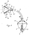
- a headlight unit for motor vehicles essentially consists of a Light module 1 using a light guide 2 with a light decoupling element 3 is connected.
- the light module 1 has a light source 4, which in one Focal point of an ellipsoidal reflector 5 is arranged. That through the Light source 4 generated light is so through the reflector 5 on a light entry surface of the light guide 2 focuses that it is transmitted in the same another end 6 of the same embossed into the light decoupling element 3 and then through a light exit surface 7 of the light decoupling element 3 is emitted in such a way that a desired light distribution is generated.
- the light decoupling element 3 is used for generation a broadly distributed light distribution, for example a fog light. It has two parallel side walls 8, the opposite via transverse walls 9 which diverge in the direction of light propagation are connected. Since the transverse walls 9 are rectangular are, the light decoupling element is rectangular in cross section.
- the light exit surface 7 is perpendicular to the side walls in one plane 8 convex.
- the light decoupling element is used to protect against mechanical stress 3 enclosed in a housing 10 adapted to the shape thereof, that continuously surrounds the light decoupling element 3. Only the light exit surface 7 of the light decoupling element 3 and the rear connection part to the light guide 2 are exposed.
- a Seal 11 is provided, which is flush as a circumferential seal on the front Edge of the housing 10 between the same and the light coupling element 3 extends.
- the seal 11 consists of a rubber-elastic material, which is injection molded onto an inside of the housing 10, preferably after a two-component injection molding process. This makes it a fixed and positionally secure arrangement of the seal 11 enables the insertion of the light decoupling element 3 in the housing 10 simplified.
- a round seal 12 which between the inside of the Housing 10 and the light decoupling element 3 is arranged. It stretches circularly around the light decoupling element 3 and promotes a centered Position of the light decoupling element 3 within the housing 10.
- the round seal 12, like the seal 11, is injection molded onto the inside of the housing 10.
- the housing 10 is mounted in a cup-shaped housing receptacle 13 has a connecting piece 14, which engages with the end 6 of the light guide 2 can be.
- the housing receptacle 13 has two opposite Latching arms 15, which are not shown in a connecting area 16 in FIG Recesses of the transverse walls 9 engage and form a radial Force component against the opposite transverse walls 9 to press.
- a self-locking bracket of the housing 10 in the Housing receptacle 13 achieved.
- the light decoupling element 3 is in this way mechanically protected and due to the simple geometric Formation (rectangular shape) of the housing receptacle 13 in a simple manner be fixed to a body opening of a motor vehicle.
- the light decoupling element 3 therefore has a compact and robust structure, wherein the housing receptacle 13 additionally as a buffer against undesirable Serves bumps.
- the light module 1 has a housing 17 on, which is connected to a light guide receptacle 18.
- the light guide 2 is as flexible light guide 2 formed.
- the light guide 2 can also be rigid and be straight, so that the light guide receptacle 18 or the housing 17 can be integrally connected to the housing receptacle 13.
- the round seals 12, 12 ' can be omitted.
- the Light decoupling element 3 consists of a transparent material, preferably made of glass or PMMA, with reflective vapor deposition on the back is.
- the housing 10 can also be screwed inside the housing receptacle 13 can be held.
- Both the housing 10 and the housing receptacle 13 also consist of a relatively rigid, non-transparent Plastic material.
- the headlight unit according to the invention is preferably suitable as an additional headlight for motor vehicles that are retrofitted to the body, preferably in a body opening.
- the housing receptacle 13 in connection with The light guide receptacle 18 and the housing 17 of the light module 1 can be advantageous the effort required to achieve the tightness of the light decoupling element 3 can be reduced.
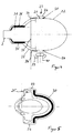
- a light decoupling element 20 has a fog light function on.
- the light decoupling element 20 has two opposing parallel ones Shell surfaces 21, on the inside of which a total reflection of the Light guide 2 coupled light rays occurs before passing through an arcuate Light exit surface 22 of the light decoupling element 20 leave the same.
- the arcuate light exit surface 22 goes in a rear area 23 of the light decoupling element 20 in a straight surface, so that is also referred to as the outer surface 21.
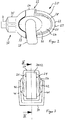
- the light decoupling element 20 is enclosed in a one-piece housing 24, that surrounds the lateral surfaces 21 of the light decoupling element 20 in a sealing manner.
- the housing 24 is in the form of a tunnel-shaped light decoupling element formed with a through opening 25 for receiving the light decoupling element 20.
- the light decoupling element receptacle 24 has a long and short side walls 26 and 27, which are flat on the lateral surfaces 21 of the light decoupling element 20.
- the long and short cover Side walls 26, 27 essentially the flat lateral surfaces 21 of the light decoupling element 20.
- a front contour 28 of the long and short side walls 26, 27 correspond to an edge 29 of the light exit surface 22 of the light decoupling element 20. In this way Except for the light exit surface, the entire surface of the light decoupling element 20 sealed and protected.
- a light guide receptacle 32 provided on a light coupling element 20 facing side has a C-shaped fastening element 33 which is form-fitting or clamping on a rear side of the light decoupling element receptacle 24 is attached.
- a circumferential edge is used 34 of the C-shaped fastening element 33, on the one hand, in contact with one Inside of the light decoupling element receptacle 24 and on the other hand under blunt system on a back of the light decoupling element 20 in the rear region of the through opening 25.
- this has a hollow cylindrical Extension 35 in which the cylindrical end by means of a The peripheral surface of the same encompassing sleeve 36 is held in a clamping manner.
- the Sleeve 36 can be made of a flexible material.
- the cylindrical end 31 is mounted in the light guide receptacle 32 in such a way that an end face 37 of the cylindrical end 31 is flat on a rear side End of the light decoupling element 20 is present.
- a U-shaped holding element 38 is provided, which in an apex region 39 can be fastened to the body part by means of a screw 40 is.
- the holding element 38 has opposite resilient legs 41 with openings that snap into place with bulges 42 on the long side walls 26 of the light decoupling element receptacle 24 are connected.
- the connecting line of the bulges 42 and the openings of the Leg ends 41 form an axis of rotation that is perpendicular to the optical axis and arranged in a cutting manner.
- the axis of rotation preferably runs in the horizontal direction, so that the housing 24 with the light decoupling element 20 is adjustable in height.
- the light exit surface 22 of the light decoupling element 20 can be avoided have a coating of abrasion.
- the coating can be used for one by spraying onto the light exit surface 22 or by application a slide can be created.
Landscapes
- Engineering & Computer Science (AREA)
- General Engineering & Computer Science (AREA)
- Physics & Mathematics (AREA)
- General Physics & Mathematics (AREA)
- Optics & Photonics (AREA)
- Non-Portable Lighting Devices Or Systems Thereof (AREA)
- Lighting Device Outwards From Vehicle And Optical Signal (AREA)
- Arrangement Of Elements, Cooling, Sealing, Or The Like Of Lighting Devices (AREA)
Applications Claiming Priority (4)
| Application Number | Priority Date | Filing Date | Title |
|---|---|---|---|
| DE19959035 | 1999-12-08 | ||
| DE19959035 | 1999-12-08 | ||
| DE10028282 | 2000-06-07 | ||
| DE10028282A DE10028282A1 (de) | 1999-12-08 | 2000-06-07 | Scheinwerfereinheit für Fahrzeuge |
Publications (3)
| Publication Number | Publication Date |
|---|---|
| EP1106909A2 true EP1106909A2 (fr) | 2001-06-13 |
| EP1106909A3 EP1106909A3 (fr) | 2004-03-17 |
| EP1106909B1 EP1106909B1 (fr) | 2005-12-28 |
Family
ID=26006009
Family Applications (1)
| Application Number | Title | Priority Date | Filing Date |
|---|---|---|---|
| EP00126735A Expired - Lifetime EP1106909B1 (fr) | 1999-12-08 | 2000-12-06 | Ensemble projecteur pour véhicules |
Country Status (4)
| Country | Link |
|---|---|
| US (1) | US6533442B2 (fr) |
| EP (1) | EP1106909B1 (fr) |
| DE (1) | DE50011967D1 (fr) |
| ES (1) | ES2254104T3 (fr) |
Families Citing this family (2)
| Publication number | Priority date | Publication date | Assignee | Title |
|---|---|---|---|---|
| US7220031B1 (en) | 2005-02-24 | 2007-05-22 | Jason Lowman | Automobile wheel lighting system |
| EP2628638B1 (fr) * | 2012-02-17 | 2021-08-11 | Flex-N-Gate France | Élément de carrosserie d'automobile comprenant une source de lumière sur sa face interne |
Citations (1)
| Publication number | Priority date | Publication date | Assignee | Title |
|---|---|---|---|---|
| DE4313914A1 (de) | 1993-04-28 | 1994-11-03 | Bosch Gmbh Robert | Scheinwerferanlage für Fahrzeuge |
Family Cites Families (11)
| Publication number | Priority date | Publication date | Assignee | Title |
|---|---|---|---|---|
| US1652340A (en) * | 1926-01-25 | 1927-12-13 | William E Adair | Vehicle headlight |
| US1626626A (en) * | 1926-02-02 | 1927-05-03 | Rawak George | Headlight |
| US3558872A (en) * | 1968-09-09 | 1971-01-26 | Sylvania Electric Prod | Automotive driving light |
| US3683167A (en) * | 1970-07-01 | 1972-08-08 | Dyonics Inc | Mounting device for light pipe |
| FR2442399A1 (fr) * | 1978-11-24 | 1980-06-20 | Cibie Projecteurs | Projecteur de vehicule automobile protege des effets des bris de glace et des agents exterieurs |
| FR2472135A1 (fr) | 1979-12-20 | 1981-06-26 | Cibie Projecteurs | Projecteur, notamment pour vehicules automobiles |
| US4811172A (en) * | 1987-11-23 | 1989-03-07 | General Electric Company | Lighting systems employing optical fibers |
| US4868718A (en) * | 1989-03-13 | 1989-09-19 | General Electric Company | Forward illumination lighting system for vehicles |
| IT1237274B (it) * | 1989-11-17 | 1993-05-27 | Carello Spa | Gruppo di illuminazione per veicoli, in particolare autoveicoli |
| US5184883A (en) * | 1992-05-01 | 1993-02-09 | General Electric Company | Automobile lighting system that includes an exterior indicating device |
| US6328464B1 (en) * | 1998-04-21 | 2001-12-11 | Litton Systems, Inc. | Luminaire using right angle film |
-
2000
- 2000-12-06 DE DE50011967T patent/DE50011967D1/de not_active Expired - Fee Related
- 2000-12-06 EP EP00126735A patent/EP1106909B1/fr not_active Expired - Lifetime
- 2000-12-06 ES ES00126735T patent/ES2254104T3/es not_active Expired - Lifetime
- 2000-12-08 US US09/731,808 patent/US6533442B2/en not_active Expired - Fee Related
Patent Citations (1)
| Publication number | Priority date | Publication date | Assignee | Title |
|---|---|---|---|---|
| DE4313914A1 (de) | 1993-04-28 | 1994-11-03 | Bosch Gmbh Robert | Scheinwerferanlage für Fahrzeuge |
Also Published As
| Publication number | Publication date |
|---|---|
| DE50011967D1 (de) | 2006-02-02 |
| US20010014024A1 (en) | 2001-08-16 |
| ES2254104T3 (es) | 2006-06-16 |
| EP1106909B1 (fr) | 2005-12-28 |
| US6533442B2 (en) | 2003-03-18 |
| EP1106909A3 (fr) | 2004-03-17 |
Similar Documents
| Publication | Publication Date | Title |
|---|---|---|
| DE10237607B4 (de) | Kameraanordnung für Kraftfahrzeuge | |
| DE102007010023A1 (de) | Fahrzeugleuchte | |
| DE19933724A1 (de) | Seitenblinkleuchte | |
| EP0745511A2 (fr) | Dispositif d'éclairage pour véhicule | |
| DE3616694C2 (de) | Beleuchtungs-Einrichtung für Fahrzeuge, insbesondere für Kraftfahrzeuge | |
| EP1106909A2 (fr) | Ensemble projecteur pour véhicules | |
| DE202006003392U1 (de) | Fahrzeugleuchte | |
| DE19919296A1 (de) | Leuchte für Fahrzeuge | |
| DE4434667A1 (de) | Scheinwerfer für Fahrzeuge | |
| DE3215685A1 (de) | Leuchtkontrolle fuer fahrzeugscheinwerfer | |
| DE4133527C2 (de) | Scheinwerfer für Kraftfahrzeuge | |
| DE10028282A1 (de) | Scheinwerfereinheit für Fahrzeuge | |
| DE69400548T2 (de) | Zusatzwarnleuchte für Fahrzeuge | |
| EP3456555A1 (fr) | Attelage de remorque | |
| EP1070632A2 (fr) | Phare de véhicule | |
| DE19757927C1 (de) | Signalleuchte für Fahrzeuge | |
| WO2002022402A1 (fr) | Passage de cable dans une porte de vehicule | |
| DE2217277C2 (de) | Glühlampenfassung, insbesondere für Kraftfahrzeug Scheinwerfer | |
| DE3306395C2 (de) | Scheinwerfer, insbesondere für Kraftfahrzeuge | |
| DE102005021704A1 (de) | Fahrzeugscheinwerfer | |
| EP0985871A2 (fr) | Projecteur et procédé de fabrication de celui-ci | |
| DE102020104635B4 (de) | Halteelement für eine Beleuchtungseinrichtung eines Kraftfahrzeugs sowie Leuchtenanordnung an einem Kraftfahrzeug | |
| DE19822354A1 (de) | Steckereinsatz für zylindrische Sensoren | |
| DE29821068U1 (de) | Scheinwerfer für Fahrzeuge | |
| DE10258535A1 (de) | Scheinwerfer mit einer Strahlenblende für ein Fahrzeug |
Legal Events
| Date | Code | Title | Description |
|---|---|---|---|
| PUAI | Public reference made under article 153(3) epc to a published international application that has entered the european phase |
Free format text: ORIGINAL CODE: 0009012 |
|
| AK | Designated contracting states |
Kind code of ref document: A2 Designated state(s): AT BE CH CY DE DK ES FI FR GB GR IE IT LI LU MC NL PT SE TR |
|
| AX | Request for extension of the european patent |
Free format text: AL;LT;LV;MK;RO;SI |
|
| PUAL | Search report despatched |
Free format text: ORIGINAL CODE: 0009013 |
|
| AK | Designated contracting states |
Kind code of ref document: A3 Designated state(s): AT BE CH CY DE DK ES FI FR GB GR IE IT LI LU MC NL PT SE TR |
|
| AX | Request for extension of the european patent |
Extension state: AL LT LV MK RO SI |
|
| RIC1 | Information provided on ipc code assigned before grant |
Ipc: 7F 21V 15/04 B Ipc: 7F 21S 8/12 A Ipc: 7B 60Q 1/00 B Ipc: 7F 21V 5/00 B Ipc: 7F 21V 17/00 B Ipc: 7G 02B 6/00 B |
|
| RAP1 | Party data changed (applicant data changed or rights of an application transferred) |
Owner name: HELLA KGAA HUECK & CO. |
|
| AKX | Designation fees paid | ||
| REG | Reference to a national code |
Ref country code: DE Ref legal event code: 8566 |
|
| 17P | Request for examination filed |
Effective date: 20041016 |
|
| R17P | Request for examination filed (corrected) |
Effective date: 20041016 |
|
| RBV | Designated contracting states (corrected) |
Designated state(s): DE ES FR IT |
|
| GRAP | Despatch of communication of intention to grant a patent |
Free format text: ORIGINAL CODE: EPIDOSNIGR1 |
|
| GRAS | Grant fee paid |
Free format text: ORIGINAL CODE: EPIDOSNIGR3 |
|
| GRAA | (expected) grant |
Free format text: ORIGINAL CODE: 0009210 |
|
| AK | Designated contracting states |
Kind code of ref document: B1 Designated state(s): DE ES FR IT |
|
| PG25 | Lapsed in a contracting state [announced via postgrant information from national office to epo] |
Ref country code: IT Free format text: LAPSE BECAUSE OF NON-PAYMENT OF DUE FEES Effective date: 20051228 |
|
| REF | Corresponds to: |
Ref document number: 50011967 Country of ref document: DE Date of ref document: 20060202 Kind code of ref document: P |
|
| REG | Reference to a national code |
Ref country code: ES Ref legal event code: FG2A Ref document number: 2254104 Country of ref document: ES Kind code of ref document: T3 |
|
| ET | Fr: translation filed | ||
| PLBE | No opposition filed within time limit |
Free format text: ORIGINAL CODE: 0009261 |
|
| STAA | Information on the status of an ep patent application or granted ep patent |
Free format text: STATUS: NO OPPOSITION FILED WITHIN TIME LIMIT |
|
| 26N | No opposition filed |
Effective date: 20060929 |
|
| PGFP | Annual fee paid to national office [announced via postgrant information from national office to epo] |
Ref country code: ES Payment date: 20080118 Year of fee payment: 8 Ref country code: FR Payment date: 20071210 Year of fee payment: 8 |
|
| PGFP | Annual fee paid to national office [announced via postgrant information from national office to epo] |
Ref country code: DE Payment date: 20071129 Year of fee payment: 8 |
|
| REG | Reference to a national code |
Ref country code: FR Ref legal event code: ST Effective date: 20090831 |
|
| PG25 | Lapsed in a contracting state [announced via postgrant information from national office to epo] |
Ref country code: DE Free format text: LAPSE BECAUSE OF NON-PAYMENT OF DUE FEES Effective date: 20090701 |
|
| REG | Reference to a national code |
Ref country code: ES Ref legal event code: FD2A Effective date: 20081209 |
|
| PG25 | Lapsed in a contracting state [announced via postgrant information from national office to epo] |
Ref country code: ES Free format text: LAPSE BECAUSE OF NON-PAYMENT OF DUE FEES Effective date: 20081209 Ref country code: FR Free format text: LAPSE BECAUSE OF NON-PAYMENT OF DUE FEES Effective date: 20081231 |
|
| PG25 | Lapsed in a contracting state [announced via postgrant information from national office to epo] |
Ref country code: IT Free format text: LAPSE BECAUSE OF NON-PAYMENT OF DUE FEES Effective date: 20071206 |