EP1107219A2 - Amelioration dynamique d'un image de lumiere residuelle pour un panneau d'affichage à plasma - Google Patents
Amelioration dynamique d'un image de lumiere residuelle pour un panneau d'affichage à plasma Download PDFInfo
- Publication number
- EP1107219A2 EP1107219A2 EP00310732A EP00310732A EP1107219A2 EP 1107219 A2 EP1107219 A2 EP 1107219A2 EP 00310732 A EP00310732 A EP 00310732A EP 00310732 A EP00310732 A EP 00310732A EP 1107219 A2 EP1107219 A2 EP 1107219A2
- Authority
- EP
- European Patent Office
- Prior art keywords
- subfields
- pulses
- subfield
- pixel value
- frame
- Prior art date
- Legal status (The legal status is an assumption and is not a legal conclusion. Google has not performed a legal analysis and makes no representation as to the accuracy of the status listed.)
- Withdrawn
Links
Images













Classifications
-
- G—PHYSICS
- G09—EDUCATION; CRYPTOGRAPHY; DISPLAY; ADVERTISING; SEALS
- G09G—ARRANGEMENTS OR CIRCUITS FOR CONTROL OF INDICATING DEVICES USING STATIC MEANS TO PRESENT VARIABLE INFORMATION
- G09G3/00—Control arrangements or circuits, of interest only in connection with visual indicators other than cathode-ray tubes
- G09G3/20—Control arrangements or circuits, of interest only in connection with visual indicators other than cathode-ray tubes for presentation of an assembly of a number of characters, e.g. a page, by composing the assembly by combination of individual elements arranged in a matrix no fixed position being assigned to or needed to be assigned to the individual characters or partial characters
- G09G3/22—Control arrangements or circuits, of interest only in connection with visual indicators other than cathode-ray tubes for presentation of an assembly of a number of characters, e.g. a page, by composing the assembly by combination of individual elements arranged in a matrix no fixed position being assigned to or needed to be assigned to the individual characters or partial characters using controlled light sources
- G09G3/28—Control arrangements or circuits, of interest only in connection with visual indicators other than cathode-ray tubes for presentation of an assembly of a number of characters, e.g. a page, by composing the assembly by combination of individual elements arranged in a matrix no fixed position being assigned to or needed to be assigned to the individual characters or partial characters using controlled light sources using luminous gas-discharge panels, e.g. plasma panels
- G09G3/288—Control arrangements or circuits, of interest only in connection with visual indicators other than cathode-ray tubes for presentation of an assembly of a number of characters, e.g. a page, by composing the assembly by combination of individual elements arranged in a matrix no fixed position being assigned to or needed to be assigned to the individual characters or partial characters using controlled light sources using luminous gas-discharge panels, e.g. plasma panels using AC panels
- G09G3/291—Control arrangements or circuits, of interest only in connection with visual indicators other than cathode-ray tubes for presentation of an assembly of a number of characters, e.g. a page, by composing the assembly by combination of individual elements arranged in a matrix no fixed position being assigned to or needed to be assigned to the individual characters or partial characters using controlled light sources using luminous gas-discharge panels, e.g. plasma panels using AC panels controlling the gas discharge to control a cell condition, e.g. by means of specific pulse shapes
-
- G—PHYSICS
- G09—EDUCATION; CRYPTOGRAPHY; DISPLAY; ADVERTISING; SEALS
- G09G—ARRANGEMENTS OR CIRCUITS FOR CONTROL OF INDICATING DEVICES USING STATIC MEANS TO PRESENT VARIABLE INFORMATION
- G09G3/00—Control arrangements or circuits, of interest only in connection with visual indicators other than cathode-ray tubes
- G09G3/20—Control arrangements or circuits, of interest only in connection with visual indicators other than cathode-ray tubes for presentation of an assembly of a number of characters, e.g. a page, by composing the assembly by combination of individual elements arranged in a matrix no fixed position being assigned to or needed to be assigned to the individual characters or partial characters
- G09G3/2007—Display of intermediate tones
- G09G3/2018—Display of intermediate tones by time modulation using two or more time intervals
- G09G3/2022—Display of intermediate tones by time modulation using two or more time intervals using sub-frames
-
- G—PHYSICS
- G09—EDUCATION; CRYPTOGRAPHY; DISPLAY; ADVERTISING; SEALS
- G09G—ARRANGEMENTS OR CIRCUITS FOR CONTROL OF INDICATING DEVICES USING STATIC MEANS TO PRESENT VARIABLE INFORMATION
- G09G3/00—Control arrangements or circuits, of interest only in connection with visual indicators other than cathode-ray tubes
- G09G3/20—Control arrangements or circuits, of interest only in connection with visual indicators other than cathode-ray tubes for presentation of an assembly of a number of characters, e.g. a page, by composing the assembly by combination of individual elements arranged in a matrix no fixed position being assigned to or needed to be assigned to the individual characters or partial characters
- G09G3/2007—Display of intermediate tones
- G09G3/2018—Display of intermediate tones by time modulation using two or more time intervals
- G09G3/2022—Display of intermediate tones by time modulation using two or more time intervals using sub-frames
- G09G3/2037—Display of intermediate tones by time modulation using two or more time intervals using sub-frames with specific control of sub-frames corresponding to the least significant bits
-
- G—PHYSICS
- G09—EDUCATION; CRYPTOGRAPHY; DISPLAY; ADVERTISING; SEALS
- G09G—ARRANGEMENTS OR CIRCUITS FOR CONTROL OF INDICATING DEVICES USING STATIC MEANS TO PRESENT VARIABLE INFORMATION
- G09G3/00—Control arrangements or circuits, of interest only in connection with visual indicators other than cathode-ray tubes
- G09G3/20—Control arrangements or circuits, of interest only in connection with visual indicators other than cathode-ray tubes for presentation of an assembly of a number of characters, e.g. a page, by composing the assembly by combination of individual elements arranged in a matrix no fixed position being assigned to or needed to be assigned to the individual characters or partial characters
- G09G3/22—Control arrangements or circuits, of interest only in connection with visual indicators other than cathode-ray tubes for presentation of an assembly of a number of characters, e.g. a page, by composing the assembly by combination of individual elements arranged in a matrix no fixed position being assigned to or needed to be assigned to the individual characters or partial characters using controlled light sources
- G09G3/28—Control arrangements or circuits, of interest only in connection with visual indicators other than cathode-ray tubes for presentation of an assembly of a number of characters, e.g. a page, by composing the assembly by combination of individual elements arranged in a matrix no fixed position being assigned to or needed to be assigned to the individual characters or partial characters using controlled light sources using luminous gas-discharge panels, e.g. plasma panels
- G09G3/288—Control arrangements or circuits, of interest only in connection with visual indicators other than cathode-ray tubes for presentation of an assembly of a number of characters, e.g. a page, by composing the assembly by combination of individual elements arranged in a matrix no fixed position being assigned to or needed to be assigned to the individual characters or partial characters using controlled light sources using luminous gas-discharge panels, e.g. plasma panels using AC panels
- G09G3/291—Control arrangements or circuits, of interest only in connection with visual indicators other than cathode-ray tubes for presentation of an assembly of a number of characters, e.g. a page, by composing the assembly by combination of individual elements arranged in a matrix no fixed position being assigned to or needed to be assigned to the individual characters or partial characters using controlled light sources using luminous gas-discharge panels, e.g. plasma panels using AC panels controlling the gas discharge to control a cell condition, e.g. by means of specific pulse shapes
- G09G3/292—Control arrangements or circuits, of interest only in connection with visual indicators other than cathode-ray tubes for presentation of an assembly of a number of characters, e.g. a page, by composing the assembly by combination of individual elements arranged in a matrix no fixed position being assigned to or needed to be assigned to the individual characters or partial characters using controlled light sources using luminous gas-discharge panels, e.g. plasma panels using AC panels controlling the gas discharge to control a cell condition, e.g. by means of specific pulse shapes for reset discharge, priming discharge or erase discharge occurring in a phase other than addressing
- G09G3/2927—Details of initialising
-
- G—PHYSICS
- G09—EDUCATION; CRYPTOGRAPHY; DISPLAY; ADVERTISING; SEALS
- G09G—ARRANGEMENTS OR CIRCUITS FOR CONTROL OF INDICATING DEVICES USING STATIC MEANS TO PRESENT VARIABLE INFORMATION
- G09G2320/00—Control of display operating conditions
- G09G2320/02—Improving the quality of display appearance
- G09G2320/0261—Improving the quality of display appearance in the context of movement of objects on the screen or movement of the observer relative to the screen
-
- G—PHYSICS
- G09—EDUCATION; CRYPTOGRAPHY; DISPLAY; ADVERTISING; SEALS
- G09G—ARRANGEMENTS OR CIRCUITS FOR CONTROL OF INDICATING DEVICES USING STATIC MEANS TO PRESENT VARIABLE INFORMATION
- G09G2320/00—Control of display operating conditions
- G09G2320/02—Improving the quality of display appearance
- G09G2320/0266—Reduction of sub-frame artefacts
-
- G—PHYSICS
- G09—EDUCATION; CRYPTOGRAPHY; DISPLAY; ADVERTISING; SEALS
- G09G—ARRANGEMENTS OR CIRCUITS FOR CONTROL OF INDICATING DEVICES USING STATIC MEANS TO PRESENT VARIABLE INFORMATION
- G09G2320/00—Control of display operating conditions
- G09G2320/02—Improving the quality of display appearance
- G09G2320/0271—Adjustment of the gradation levels within the range of the gradation scale, e.g. by redistribution or clipping
- G09G2320/0276—Adjustment of the gradation levels within the range of the gradation scale, e.g. by redistribution or clipping for the purpose of adaptation to the characteristics of a display device, i.e. gamma correction
-
- G—PHYSICS
- G09—EDUCATION; CRYPTOGRAPHY; DISPLAY; ADVERTISING; SEALS
- G09G—ARRANGEMENTS OR CIRCUITS FOR CONTROL OF INDICATING DEVICES USING STATIC MEANS TO PRESENT VARIABLE INFORMATION
- G09G2360/00—Aspects of the architecture of display systems
- G09G2360/16—Calculation or use of calculated indices related to luminance levels in display data
Definitions
- the present invention relates to video displays and, more particularly, to a method and system for improving the image quality of a display in which a pixel is illuminated by pulses generated in subfields of a frame of the image in accordance with a pulse distribution function.
- a maximum pixel value to be imaged during the frame is determined, and the pulse distribution is modified based on the maximum pixel value.
- the invention is particularly suited for use with plasma display panels.
- Digital displays such as alternating current (AC) Plasma Display Panels (PDPs) are evolving as an attractive choice to view television programming, especially with regard to the emerging digital television and high definition television (DTV/HDTV) formats.
- Conventional cathode ray tubes (CRTs) have an established high picture quality, and PDPs are striving to achieve a similar quality in order to attract widespread consumer acceptance.
- PDPs i.e., gas discharge panels
- PDPs are well known in the art and, in general, comprise a structure including a pair of substrates respectively supporting column and row electrodes, each coated with a dielectric layer and disposed in parallel spaced relation to define a gap therebetween in which an ionizable gas is sealed.
- the substrates are arranged such that the electrodes are disposed in orthogonal relation to each other, thereby defining points of intersection which, in turn, define discharge pixel sites at which selective discharges may be established to provide a desired storage or display function.
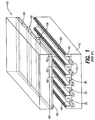
- Plasma panel 410 includes a back substrate 412 upon which plural column address electrodes 414 are supported. Column address electrodes 414 are separated by barrier ribs 416 and are covered by red, green and blue phosphors 418, 420 and 422, respectively.
- a front transparent substrate 424 includes a pair of sustain electrodes 426 and 428 for each row of pixel sites.
- a dielectric layer 430 is emplaced on front substrate 424 and a magnesium oxide overcoat layer 432 covers the entire lower surface thereof, including all of sustain electrodes 426 and 428.
- Fig. 1 The structure of Fig. 1 is sometimes called a single substrate AC plasma display since both sustain electrodes 426 and 428, for each row, are on a single substrate of the panel.
- An inert gas mixture is positioned between substrates 412 and 424 and is excited to a discharge state by sustain voltages applied by sustain electrodes 426 and 428.
- the discharging inert gas produces ultraviolet light that excites the red, green and blue phosphor layers 418, 420 and 422, respectively to emit visible light. If the driving voltages applied to column address electrodes 414 and sustain electrodes 426, 428 are appropriately controlled, a full color image is visible through front substrate 424.
- a means of achieving a gray scale is needed. Since it is desirable to operate AC plasma panels in a memory mode to achieve high luminance and low flicker, an addressing technique is utilized to achieve image gray levels in pixels that only exist in the ON or OFF states. Such addressing technique is described by Yoshikawa et al. in "A Full Color AC Plasma Display With 256 Gray Scale", Japan Display, 1992, pp. 605-608. Because a PDP is a digital device, it can provide only a fixed number of gray scale gradations. In the case of an 8-bit red-green-blue (RGB) signal, 256 gradations are possible.
- RGB red-green-blue
- Fig. 2 illustrates the driving sequence used by Yoshikawa et al. to achieve a 256 gray scale.
- the drive sequence is sometimes called the sub-field addressing method.
- the plasma display panel is addressed in a conventional video manner that divides images into frames. A typical video image may be presented at 60 frames per second, which corresponds to a frame time of 16.6 milliseconds.
- the sub-field addressing method shown in Fig. 2 divides each frame into 8 sub-fields, SF1-SF8.
- each of the 8 sub-fields is further divided into an address period and a sustain period.
- a sustain voltage is applied to sustain electrodes 26 and 28.
- the sustain voltage is insufficient to cause a discharge at any pixel site that is in the OFF state.
- the first sub-field has a sustain period with only 1 complete sustain cycle period.
- the second sub-field has 2 sustain cycles, the third sub-field has a sustain period with 4 sustain cycles and, so forth, until the 8th sub-field which has a sustain period with 128 sustain cycles.
- the perceived intensity of the pixel site can be varied to any one of the 256 gray scale levels.
- a selective write address pulse is applied to the pixel site during sub-field 8 by applying an appropriate voltage to a column address electrode 14, and utilizing one of sustain lines 26, 28 as the opposing address conductor. No address pulses are applied during the other sub-fields to the addressed pixel site. This means that during the first 7 sub-fields, there is no writing action and therefore no light is emitted during the sustain periods.
- the selective write action turns ON the selected pixel site and causes an emission of light therefrom during the sub-field 8 sustain period, in this case for 128 sustain cycles.
- the 128 sustain cycle per frame energization corresponds to a half-intensity for a frame time.
- a selective write address pulse is applied to the pixel site during sub-field 7 and no address pulses are applied during the other sub-fields.
- the selective write turns ON the selected pixel site and causes an emission of light during the sub-field sustain period (in this case, for 64 sustain cycles corresponding to a 1-quarter intensity).
- the selective write address pulse is applied during all 8 sub-fields so that the pixel site emits light for all sustain periods for each of the 8 sub-fields, corresponding to a full-intensity for the frame.
- the Yoshikawa et al. procedure enables any of 256 different intensities to be achieved through the action of a display processor supplying an 8-bit data word for each sub-pixel site, the data word corresponding to the desired gray intensity level.
- the 8-bit data word controls the number of sustain cycles during which the selected pixel site will emit light for that frame.
- any integer number of sustain cycles per frame between and including 0-255 is obtainable.
- Fig. 4 shows a standard sustain pulse distribution over 8 subfields for an 8-bit grayscale.
- the sustain pulse distribution is binary-weighted. That is, each subsequent subfield will contain twice the number of pulses as the previous subfield.
- a PDP system is not limited to 8 subfields per frame.
- Japanese Patent No. H10-107573 to Mori describes a system in which the pulses for the 8-bit grayscale are distributed over 12 subfields.
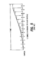
- Fig. 5 shows an example of a 12-subfield sustain pulse distribution for an 8-bit grayscale, similar to that described in the Mori patent.
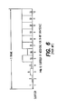
- FIG. 6 shows an example of a PWM 12-subfield sustain pulse distribution for an 8-bit grayscale.
- Output _ Data Input _ Range x Input _ Code Input _ Range 2.2
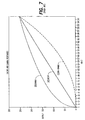
- Fig. 7 is a graph representing the gamma correction function (Curve B), the inverse gamma function (Curve C) and a desired linear output function (Curve A).
- Inverse-gamma correction greatly reduces the number of gradations represented on the display. While the linear response allows 256 different output values, the inverse-gamma curve allows only 184 different output values. This is most evident in the low-level image data where the input value must change considerably to achieve a small change in the output value. As the input value increases, the slope of the curve increases, so that at high input levels a small change of input produces a large change of brightness.
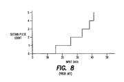
- Fig. 8 is a graph of the gamma correction function for input values ranging from 0 to 40 counts of conventional video signal data. Note that an input value of 15 is required before any change is produced at the output, and input values of 16 through 25 all produce an output value of 1. Consequently, at low intensity levels, a viewer sees a set of wide contours, each consisting of a single value decoded from a larger number of input values.
- a display controller for a PDP receives the gamma corrected input data, applies the inverse gamma function and enables individual subfields to produce a desired level of luminance. Since different types of digital displays produce different amounts of light and may have different brightness requirements, the amount of light produced varies. This requires use of a scaling operation to weight the subfields to yield full intensity. To preserve the linearity of the display, the subfields are binary coded, i.e., each subfield produces twice the light as the previous subfield, as described above. When the number of pulses in each subfield is scaled to meet a brightness requirement, the binary weighting is scaled. For example, to increase the brightness by 5 times, quantities of 5, 10, 20, 40, 80, 160, 320, and 640 sustain pulses are implemented in subfields 1 through 8, respectively.
- a pixel that is to be illuminated in a subfield is first activated by a write voltage applied to the electrodes that define the pixel. Nonetheless, the pixel is addressed and sustain pulses are generated regardless of whether the pixel is to be illuminated.
- the addressing of the pixel and the generation of sustain pulses in a subfield within which a pixel will not be illuminated is a waste of power.
- a storage media including instructions for controlling a processor and a system for improving an image on a display that images pixels.
- Each of the pixels has an intensity represented by a respective pixel value, an intensity of a given pixel being associated with a number of pulses produced within a set of subfields in a frame-time, and the pulses allocated among the set of subfields in accordance with a pulse distribution.
- the method comprises the steps of determining a maximum pixel value to be imaged during the frame-time, and altering a number of pulses within a given subfield based on the maximum pixel value, thus modifying the pulse distribution.
- a storage media including instructions for controlling a processor and a system for reducing power consumed by a display that images pixels in which an intensity of a given pixel is associated with a number of pulses produced within a set of subfields in a frame-time.
- the method comprises the step of reducing power to the display during a given subfield in which none of the pulses are applied to produce the intensity of the given pixel.
- the invention takes advantage of subfields that would not ordinarily be used to produce the desired level of luminance.
- the maximum pixel value is compared to a threshold that correlates to a sustain pulse distribution boundary of a subfield.
- the threshold is related to a number of pulses allocated to subfields prior in time in a frame-time.
- the invention identifies the subfield having the smallest associated threshold that is also greater than the maximum pixel value.
- the maximum pixel value is less than a threshold, subfields occurring after that threshold can be used for the production of new pulses or for a redistribution of existing pulses.
- an unused subfield can provide a period of time during which power to the display can be reduced.
- the present invention is a method and system for improving the image quality of a display in which a pixel is illuminated by pulses generated in subfields of a frame of the image in accordance with a pulse distribution function.
- input data is frame-buffered and evaluated to determine a maximum pixel value in the frame. Thereafter, a number of pulses within a subfield is altered based on the maximum pixel value, thus the sustain pulse distribution is modified.
- the invention is particularly suited for use with PDPs.
- the modification of the sustain pulse distribution is possible because the invention takes advantage of subfields that would not ordinarily be used to produce the desired level of luminance.
- the maximum pixel value is compared to a threshold that correlates to a sustain pulse distribution boundary of a subfield.
- the threshold is related to a number of pulses allocated to subfields prior in time in a frame-time.
- the invention identifies the subfield having the smallest associated threshold that is also greater than the maximum pixel value.
- the maximum pixel value is less than a threshold, subfields occurring after that threshold can be used for the production of new pulses or for a redistribution of existing pulses.
- an unused subfield can provide a period of time during which power to the display can be reduced.
- Fig. 9 shows an 8-subfield sustain pulse distribution for an 8-bit grayscale system.
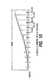
- Fig. 10 shows a 12-subfield sustain pulse distribution for an 8-bit grayscale system.
- the invention takes advantage of unused subfields by using them for the production of new pulses or for a redistribution of existing pulses.
- the 12-subfield sustain pulse distribution (Fig. 10) provides more opportunity for utilizing otherwise unused subfields than does the 8-subfield sustain pulse distribution (Fig. 9). Accordingly, the present invention can be applied more frequently in a 12-subfield system than in an 8-subfield system.
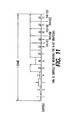
- Fig. 11 shows a pulse width modulation (PWM) 12-subfield sustain pulse distribution for an 8-bit grayscale system.
- Each of these thresholds is a greater value than that of the corresponding thresholds, TH0 - TH4, shown in Fig. 10.
- the present invention can therefore be applied more frequently with the PWM 12-subfield sustain pulse distribution (Fig. 11) than with the 12-subfield sustain pulse distribution (Fig. 10).
- tests have indicated that the distribution of Fig. 10 provides superior performance regarding a reduction of MPD artifacts. Therefore, the 12-subfield sustain pulse distribution of Fig. 10 is a preferred distribution, and it shall be assumed in the examples subsequently described herein.
- the examples presented herein assume an 8-bit pixel value and a 12-subfield sustain pulse distribution. They also assume a display capable of generating at least 255 sustain pulses per frame. However, the invention is not constrained to these examples. In general terms, the present invention can be applied to a system having an N-bit pixel value, and a display capable of producing P(2 N - 1) sustain pulses in a frame, where P is an integer greater than 0, and the number of subfields is greater than or equal to N.
- the present invention can be applied to any sequence of subfields.
- the sequence can be ordered in time from MSB to LSB, or it can be independent of an LSB-MSB ordering, such as the distribution 1, 4, 10, 19, 33, 47, 53, 40, 26, 14 6, and 2 sustain pulses.
- the present invention includes three modes of operation, for convenience referred to as Mode 1, Mode 2 and Mode 3 that may be used separately or in conjunction with each other.
- Mode 1 low-level resolution is improved by allocating one or more new pulses to an otherwise unused subfield.
- Mode 2 MPD reduction is achieved by redistributing pulses from subfields below the threshold, and including the otherwise unused subfield in the redistribution.
- Mode 3 driving circuits for the display are turned OFF during unused subfields.
- Mode 1 low-level resolution is improved by allocating one or more new pulses to an otherwise unused subfield.
- a display is capable of producing more than 255 sustain pulses in a frame, more grayscale gradations can be realized.
- the present invention can thus use an 8-bit grayscale input value to produce a pseudo grayscale value of greater than 8 bits.
- Table 1 lists the minimum number of sustain pulses that a system must be capable of producing to support various pseudo grayscaling schemes. For example, for a 12-bit pseudo grayscale, the system must be capable of producing at least 4080 sustain pulses per frame. The table also shows an allocation of pulses, and indicates the threshold levels that can possibly be realized in a system capable of providing a 12-subfield sustain pulse distribution such as that shown in Fig. 10.
- Fig. 12 shows the benefit of pseudo 9-12 grayscaling that can be realized for a low value input to the inverse gamma function.
- an 8-bit grayscale produces only three different output values, i.e., 0, 16 and 32, while a 12-bit grayscale yields 19 different output values.
- 12-bit grayscaling offers increased resolution over 9-bit grayscaling.
- a least significant bit represents 16 sustain pulses.
- the present invention produces a pseudo 9-12 bit grayscale by taking advantage of subfields that are not ordinarily used in the 8-bit grayscale system and allocating new LSBs representing 8, 4, 2 and 1 pulses.
- the present invention can produce a pseudo 12-bit grayscale (see Table 1). The following examples further illustrate the operation of Mode 1, and the technique of pseudo 9-12 bit grayscaling.
- Mode 1 Threshold 0.
- TH1 202. All twelve subfields are used, and therefore none are available for pseudo grayscaling.
- Mode 1 Threshold 1.
- Subfield 12 is not ordinarily used. Subfield 12 can therefore be used for one new LSB representing 8 sustain pulses. Pseudo 9-bit grayscaling is thus achieved.
- Mode 1 Threshold 2.
- Subfields 12 and 11 are not ordinarily used. Subfields 12 and 11 can therefore be used for two new LSBs representing 8 and 4 sustain pulses. Pseudo 10-bit grayscaling is thus achieved.
- Mode 1 Threshold 3.
- Subfields 12, 11 and 10 are not ordinarily used. Subfields 12, 11 and 10 can therefore be used for three new LSBs representing 8, 4 and 2 sustain pulses. Pseudo 11-bit grayscaling is thus achieved.
- Mode 1 Threshold 4.
- Subfields 12, 11, 10 and 9 are not ordinarily used. Subfields 12, 11, 10 and 9 can therefore be used for four new LSBs representing 8, 4, 2 and 1 sustain pulses. Pseudo 12-bit grayscaling is thus achieved.
- Mode 1 of the present invention recognizes that some subfield in the pulse distribution contains a least significant number of pulses.
- the invention identifies an unused subfield and allocates to the unused subfield a quantity of new pulses equal to one half of the least significant number.
- sustain pulses within a frame also influences the quality of an image as perceived by a viewer. This is because the human eye interprets an image by integrating the pulses, and the eye is susceptible to frame-to-frame variations in the pulse distribution.
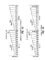
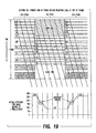
- Figs. 18 and 19 show two possible schemes for the placement of new pulses with a frame of image data.
- the figures also depict a retina response to excursions between Threshold 0 and Threshold 4 with an image moving at three pixels per frame.
- the new pulses can be situated at any point within the frame, and the ordering of the subfields can also be modified.
- Fig. 18 shows the subfields with new LSBs situated in place of the formerly unused subfields while Fig. 19 shows the subfields with new LSBs situated at the top of the frame.
- the arrangement shown in Fig. 19 can introduce 30Hz flicker and MPD artifacts when several thresholds are crossed in consecutive frames.
- Dead time is a time during which no pulse is generated.
- An additional improvement can be realized by accumulating dead time and situating the new pulses at a predetermined position within the frame with respect to the dead time. Similarly, the new pulses can be situated so that the dead time resides at a predetermined position in the frame.
- the subfields that are designated for new sustain pulses ordinarily generate a major portion of the number of pulses within the frame. Since the quantity of pulses, typically 8, 4, 2 or 1, that are allocated to these subfields is much less than the quantity that the subfields are capable of accommodating, these subfields may contain substantial amounts of dead time..
- Fig. 20 illustrates a preferred arrangement in which new pulses are situated after the accumulated dead time. Under this arrangement the new pulses will immediately precede the first subfield in the following frame. Consequently, light from the new pulses will transition smoothly into the next frame. Nonetheless, the invention is not limited to this arrangement, and the new pulses can be situated at any point within the frame with respect to the dead time. Furthermore, the dead time can be partitioned or redistributed throughout the frame.
- Some PDP systems are capable of generating sustain pulses that provide varying levels of illumination. For example, a sustain pulse having a narrow pulse width may produce less light than a sustain pulse having a wider pulse width. Also, the light emitted during addressing can be considered to be some fraction of the light emitted by one sustain pulse. In such systems, 1 ⁇ 2 and 1 ⁇ 4 brightness, and other fractional levels of brightness, can allow for increased grayscaling levels without increasing the number of sustain pulses.
- 10-bit grayscaling can be generated using whole sustain pulses (see Table 1).
- TH4 82
- MPD reduction is achieved by redistributing pulses from subfields below the threshold into one or more subfields that are otherwise unused. That is, one or more pulses from the subfields below the threshold are allocated to one or more of the otherwise unused subfields.
- the MPD reduction is achieved by reducing variations in the level of light emitted in consecutive frames so that the retina response does not integrate false contours during motion in the image.
- the advantage of using 12 subfields to represent an 8-bit pixel value is that the sustain pulses can be more linearly distributed across the subfields in a 12-subfield system than in an 8-subfield system. Reducing a delta sustain pulse count between adjacent subfields yields a reduction in MPD.
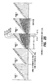
- Threshold 0. Refer to Fig. 23.
- Threshold 1 Refer to Fig. 24.
- Subfield 12 is not ordinarily used.
- the 202 sustain pulses originally in subfields 1 through 11 are redistributed over 12 subfields.
- Fig. 24, Frames 3 and 4, show a suggested redistribution.
- Mode 2 Threshold 2.
- Subfields 12 and 11 are not ordinarily used.
- the 155 sustain pulses originally in subfields 1 through 10 are redistributed over 12 subfields.
- Fig. 25, Frames 3 and 4, show a suggested redistribution.
- Mode 2 Threshold 3.
- Subfields 12, 11 and 10 are not ordinarily used.
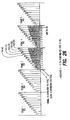
- the 115 sustain pulses originally in subfields 1 through 9 are redistributed over 12 subfields.
- Fig. 26, Frames 3 and 4, show a suggested redistribution.
- Mode 2 Threshold 4.
- Subfields 12, 11, 10 and 9 are not ordinarily used.
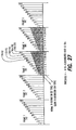
- the 82 sustain pulses originally in subfields 1 through 8 are redistributed over 12 subfields.
- Fig. 27, Frames 3 and 4, show a suggested redistribution.
- Mode 2 can be further enhanced by dynamically adjusting the thresholds based on the modified pulse distribution. That is, when the sustain pulses are redistributed over the 12 subfields, the boundaries of the subfields will change, and the thresholds of the subfields can be adjusted.
- the 202 sustain pulses from subfields 1 through 11 are redistributed over 12 subfields.
- a New TH3 129 is defined by totaling the sustain pulses from subfields 1 through 11.
- the advantage of dynamically adjusting the thresholds is that the new thresholds will be crossed at higher luminance levels, thereby allowing more opportunity for redistribution of sustain pulses and, consequently, MPD reduction.
- Another enhancement is realized by recognizing that the amount of dead time in a frame increases as a smaller total number of sustain pulses is redistributed over the 12 subfields.
- the dead time can be accumulated and allocated to create a new subfield.
- Fig. 28 illustrates the technique by which dead time is accumulated and allocated to create a new subfield.
- S/A represents a time interval required for setting up and addressing a subfield.
- subfields 9, 10, 11 and 12 will each include an interval of dead time during which no sustain pulses are generated.
- the intervals, SP9, SP10, SP11 and SP12 represent the recoverable time from the original subfields 9 through 12, respectively.
- subfields 11 and 12 are ordinarily not used. SP11 and SP12 can be recovered and allocated to create a new subfield, i.e., a thirteenth subfield.
- subfields 9, 10 11 and 12 are ordinarily not used.
- SP9, SP10, SP11 and SP12 can be recovered and allocated to create two new subfields, i.e., a thirteenth and fourteenth subfield.
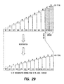
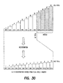
- Figs. 29 and 30 show suggested redistributions of sustain pulses to include thirteen and fourteen subfields, respectively. These distributions over thirteen and fourteen subfields further reduce the variation in the numbers of sustain pulses between subfields, which further reduces MPD.
- Mode 1 enhanced low-level resolution
- Mode 2 MPD reduction
- 4 pseudo grayscale bits can be added and 2 additional subfields can be created, for a total of 14 subfields, over which the sustain pulses can be redistributed.
- Subfield 12 is not ordinarily used. A choice may be made to utilize either Mode 1 or Mode 2.
- Combined Modes, Threshold 2. Refer to Fig. 31.
- Subfields 12 and 11 are not ordinarily used, and are thus available for image enhancement. One of these available subfields is situated on the left end of the pulse distribution and used for new LSBs (Mode 1). The other available subfield is used to allow a redistribution of sustain pulses (Mode 2).
- Combined Modes, Threshold 3. Refer to Fig. 32.
- Subfields 12, 11 and 10 are not ordinarily used, and are thus available for image enhancement. Two of these available subfields are situated on the left end of the pulse distribution and used for new LSBs (Mode 1). The other available subfield is used to allow a redistribution of sustain pulses (Mode 2). Alternatively, only one of the available subfields can be used for a new LSB, and the other two available subfields can be used for redistribution of pulses.
- Combined Modes, Threshold 4. Refer to Fig. 33.
- Subfields 12, 11, 10 and 9 are not ordinarily used, and are thus available for image enhancement. Three of these available subfields are situated on the left end of the pulse distribution and used for new LSBs (Mode 1). The other available subfield is used to allow a redistribution of sustain pulses (Mode 2). Alternatively, only one or two of the available subfields can be used for new LSBs, and the remaining available subfields can be used for redistribution of pulses.
- driving circuits for the display are turned OFF during unused subfields. This feature results in a reduction of quiescent-state power for the addressing and sustaining driver circuits.
- Fig. 34 illustrates an example of dynamic power reduction for a case where the maximum pixel value is less than or equal to Threshold 4. Subfields 9, 10, 11 and 12 are not ordinarily used. Therefore, the driver circuits can be turned OFF during these subfields. In this case, quiescent-state power to the addressing circuits is reduced by 33%, and quiescent-state power to the sustain circuits is reduced by 68%.
- the high luminance filter deals with a situation where the maximum pixel value is associated with only a small portion of the total image. For example, a bright star, 5 pixels in size, is present in a nighttime scene. The high intensity of the star is represented by a maximum pixel value that does not fall below any of the thresholds, and therefore no subfields are available for image enhancement.
- the high luminance filter overcomes this problem by discarding pixels associated with a high luminance region that represents less than a small percentage, for example 1%, of the total image. The greatest threshold level that is less than the filtered high intensity pixel value is then selected as the threshold for the frame of image data.
- the filtered data is then limited to 202. This technique assures that the filtered data is not grossly limited to a much lower threshold value, which would unnaturally limit the dynamic range of the intensity of the image.
- the hysteresis logic deals with a situation where a maximum peak value, from frame-to-frame, toggles about a threshold. This toggling will cause a 30 Hz flicker of the image as new LSBs are alternately activated and deactivated.
- the hysteresis logic overcomes this problem by creating a hysteresis band having an upper and lower boundary. A maximum pixel value must cross one of the boundaries in order for a threshold to change.
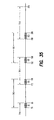
- Fig. 35 is a graph showing the thresholds, each with a hysteresis band providing ⁇ 3 counts of hysteresis.
- a maximum pixel that is initially greater than TH1 202, and therefore in the range of TH0, must fall below 199 for the threshold to transition from TH0 to TH1. Conversely, if the pixel value is in the range of TH1, it must subsequently climb to greater than 205 for the threshold to transition from TH1 to TH0.
- the scene detect logic deals with a situation where minor frame-to-frame variations in an image cause changes in the pulse distribution. These variations appear as a low rate, but undesirable, modification of the image intensity.
- the scene detect logic permits a change in threshold only when the image has changed from a previous image by a predetermined amount. That is, the scene detect logic will inhibit the alteration of the pulse distribution when the image has not changed by the predetermined amount.
- Image content for one frame is determined by summing the 8-bit data value for every full-color pixel (RGB) as it is written into a frame memory. The scene is regarded as having changed if the absolute difference of the total data content between two frames is greater than the predetermined amount.
- each threshold should be assigned an absolute maximum and minimum value so that the system will recognize a case where the maximum pixel value is well beyond the range of the current threshold, although a scene change is not detected.
- thresholds will change appropriately for slow fade-ins and fade-outs, even though the image data from frame-to-frame may not differ enough to trigger a scene change.
- Fig. 36 is a flowchart of a method for improving image quality of a display in accordance with the present invention.
- the method is implemented in a system in which the display images pixels, each with an intensity represented by a respective pixel value.
- the display is energized on a frame-time basis in which each frame includes a set of subfields.
- the intensity of a given pixel is controlled by applying sustain pulses to the subfields in accordance with a pulse distribution.
- Three modes of operation, as described above, are represented in this method. However, the method can be implemented to apply any of the three modes individually.
- the method begins with step 2.
- step 2 the method reads a frame of image data. The method then advances to step 4.
- step 4 the method evaluates the frame of image data and finds a maximum pixel value. The method then advances to step 6.
- step 6 the method evaluates the desired mode of operation for the system. If the desired mode is Mode 3, then the method branches to step 22. If the desired mode is not Mode 3, then the method advances to steps 8 and 10.
- Step 8 is an embodiment of the hysteresis logic
- step 10 is an embodiment of the high luminance filter, both of which are described above.
- the sequence in which these steps are executed is not critical to the operation of the present invention, so they are represented here as being performed in parallel.
- a given subfield has an associated threshold value related to a number of pulses allocated to subfields prior in time in the frame.
- the method defines a hysteresis band around the subfield thresholds.
- the intent of the hysteresis band is to prevent a sequence of maximum pixel values that alternate above and below an original threshold value, from toggling about the original threshold value.
- the threshold values are adjusted so that a relationship between a current maximum pixel value and the threshold is retained until a subsequent maximum pixel value changes by more than a predetermined amount from the current maximum pixel value.
- the method then advances to step 12.
- the method limits an intensity of a pixel associated with a high-luminance region of the image that represents less than a predetermined percentage of the image. This step may or may not limit the maximum pixel value, but for the sake of clarity, in subsequent steps, the result from step 10 is referred to as the resultant maximum pixel value. The method then advances to step 12.
- step 12 the method determines whether the image has changed a predetermined amount as compared to a previous image.
- This step is an embodiment of the scene detect logic described above. The point at which this step is performed is not critical to the operation of the present invention. For example, the scene detect operation of step 12 could be performed before the hysteresis operation of step 8 and the high luminance filter of step 10. If the image has not changed by the predetermined amount, then the method loops back to step 2. If the image has changed by the predetermined amount, then the method advances to step 14.
- step 14 the resultant maximum pixel value is compared to a threshold that correlates to a sustain pulse distribution boundary of a subfield.
- the threshold is related to a number of pulses allocated to subfields prior in time in a frame.
- the method identifies the subfield having the smallest associated threshold that is also greater than the maximum pixel value. When the maximum pixel value is less than a threshold, the method will alter the number of pulses allocated to subfields occurring after that threshold. The method then advances to step 16.
- step 16 the method evaluates the desired mode of operation for the system. If the desired mode is Mode 1, then the method advances to step 18. If the desired mode is Mode 2, then the method advances to step 20.
- step 18 in accordance with Mode 1, the method allocates new LSB sustain pulses to subfields that are otherwise unused.
- the method steps of Mode 1 are further described below in association with Fig. 37.
- step 20 in accordance with Mode 2, the method redistributes sustain pulses.
- the method steps of Mode 2 are further described below in association with Fig. 38.
- step 22 the resultant maximum pixel value is compared to a threshold that correlates to a sustain pulse distribution boundary of a subfield.
- the threshold is related to a number of pulses occurring prior in time in subfields in a frame. The method then advances to step 24.
- step 24 in accordance with Mode 3, the method reduces power consumed by the display.
- the method steps of Mode 3 are further described below in association with Fig. 39.
- Fig. 37 is a flowchart of a method for improving image quality of a display in accordance with Mode 1 of the present invention.
- Mode 1 modifies the pulse distribution based on the maximum pixel value in order to improve low-level resolution of the display. This method begins with step 32.
- step 32 the method identifies a subfield, based on a relationship between a threshold value and the maximum pixel value, for alteration of a number of pulses present in the subfield.
- the maximum pixel value was determined in step 4 of Fig. 36, but it may have been limited by the high luminance filter in step 10 of Fig. 36 to yield a resultant maximum pixel value.
- step 8 of Fig. 36 defined a hysteresis band about the threshold levels.
- the method compares the resultant maximum pixel value to the thresholds associated with the subfields and identifies one or more subfields having an associated threshold value that is greater than the resultant maximum pixel value.
- the method identifies a subfield having a smallest associated threshold value that is also greater than the resultant maximum pixel value. When the resultant maximum pixel value is less than a threshold, subfields occurring after that threshold can be used for the production of new pulses. The method then advances to step 34.
- step 34 the method allocates one or more new pulses to the unused subfields. The method then advances to step 36.
- step 36 the method situates subfields at desired positions within the frame.
- the one or more subfields identified in step 32 can be situated at any position in the frame, but in a preferred arrangement, the subfields will be located at the end of the frame, just prior to a beginning of a subsequent frame.
- the method then advances to step 38.
- step 38 the method accumulates dead time from the subfields with the new pulses, and situates the new pulses at an optimum position within the frame with respect to the dead time.
- new pulses are situated after the accumulated dead time.
- Fig. 38 is a flowchart of a method for improving image quality of a display in accordance with Mode 2 of the present invention.
- Mode 2 modifies the pulse distribution based on the maximum pixel value in order to reduce MPD. This method begins with step 52.
- the method identifies a subfield, based on a relationship between a threshold value and the maximum pixel value, for alteration of a number of pulses present in the subfield.
- the maximum pixel value was determined in step 4 of Fig. 36, but it may have been limited by the high luminance filter in step 10 of Fig. 36 to yield a resultant maximum pixel value.
- step 8 of Fig. 36 defined a hysteresis band about the threshold levels.
- the method compares the resultant maximum pixel value to the thresholds associated with the subfields and identifies one or more subfields having an associated threshold value that is greater than the resultant maximum pixel value.
- the method identifies a subfield having a smallest associated threshold value that is also greater than the resultant maximum pixel value. When the resultant maximum pixel value is less than a threshold, subfields occurring after that threshold can be used for a redistribution of existing pulses. The method then advances to step 54.
- step 54 the method accumulates dead time from subfields within the frame. Dead time is a time during which no pulse is generated. The method then advances to step 56.
- step 56 the method determines whether a new subfield can be created in place of the accumulated dead time. If a new subfield can be created, then the method advances to step 58. If a new subfield cannot be created, then the method branches to step 60.
- step 58 the method creates one or more new subfields from the accumulated dead time. The method then advances to step 60.
- step 60 the method redistributes pulses across all available subfields.
- the pulses required to produce the desired level of luminance are redistributed over all of the subfields, including subfields identified in step 52, and new subfields created in step 58.
- the method then advances to step 62.
- step 62 the thresholds are adjusted based on the modified pulse distribution. This step is an embodiment of the technique of dynamically adjusting the thresholds, as described above.
- Fig. 39 is a flowchart of a method for reducing power consumed by a display in accordance with Mode 3 of the present invention. This method begins with step 82.
- the method identifies an unused subfield, based on a relationship between a threshold value and the maximum pixel value.
- the maximum pixel value was determined in step 4 of Fig. 36, but it may have been limited by the high luminance filter in step 10 of Fig. 36 to yield a resultant maximum pixel value.
- step 8 of Fig. 36 defined a hysteresis band about the threshold levels.
- the method compares the resultant maximum pixel value to the thresholds associated with the subfields and identifies one or more subfields having an associated threshold value that is greater than the resultant maximum pixel value. The method identifies a subfield having a smallest associated threshold value that is also greater than the resultant maximum pixel value. When the resultant maximum pixel value is less than a threshold, subfields occurring after that threshold indicate a period of time during which power to the display can be reduced.
- step 84 the method reduces power to the display during the time of the one or more subfields identified in step 82.
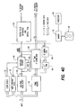
- Fig. 40 is a block diagram of a circuit for receiving an 8-bit gamma corrected video signal and improving the image quality of a display in accordance with the present invention.
- the block diagram describes the data path for one color (i.e., red, green or blue).
- the primary components of the circuit include a maximum pixel value detector 130, a frame memory 140, an inverse-gamma correction and sustain pulse coding read only memory (ROM) 180, and a sustain pulse distribution and subfield total circuit 170.
- the circuit includes a scene detect circuit 110, a high luminance filter 120, a threshold decoder 150, and a hysteresis circuit 152.
- the circuit can be implemented with discrete components or in firmware. Alternatively, it can be implemented in a processor 190, with associated memory 192. While the procedures required to execute the invention hereof are indicated as already loaded into memory 192, they may be configured on a storage media, such as data memory 194 for subsequent loading into memory 192.
- Frame memory 140 is a temporary holding area for the image data.
- Maximum pixel value detector 130 evaluates the image data while it is being written to frame memory 140. Maximum pixel value detector 130 outputs a maximum pixel value for the frame of image data.
- Scene detect circuit 110 determines whether an image has changed from a previous image by a predetermined amount. The scene is regarded as having changed if the absolute difference of the total data content between two frames is greater than a predetermined amount. It produces an output indicating whether the scene has changed.
- This circuit is an embodiment of the scene detect logic described above.
- High luminance filter 120 limits the intensity of pixels associated with a high luminance region that represents less than a small percentage of the total image. This overrides the maximum pixel value detector 130 when the filter conditions are met.
- Hysteresis circuit 152 considers the threshold of the previous frame, and the hysteresis bandwidth to determine whether a difference between a first maximum pixel value and a subsequent maximum pixel value is sufficient to warrant a transition between thresholds.
- Threshold decoder 150 produces a mode control indicating which threshold has been crossed. Table 2 lists the thresholds and corresponding mode control values. Mode Control Bits Threshold Decode Mode Control Bits 2 1 0 Threshold 0 0 0 0 Threshold 1 0 0 1 Threshold 2 0 1 0 Threshold 3 0 1 1 Threshold 4 1 0 0
- the inverse-gamma correction and sustain pulse coding ROM 180 obtains data from frame memory 140 and obtains the mode control from threshold decoder 150.
- the inverse-gamma correction and sustain pulse coding ROM 180 applies inverse gamma correction to the 8-bit image data and produces 12-bit image data that is sent to a subfield data memory.
- Mode 1 which operates to enhance low level resolution, the inverse-gamma correction and sustain pulse coding ROM 180 assign new LSBs to subfields 12, 11, 10, and 9 for TH1, TH2, TH3, and TH4, respectively, as shown in Figs. 13 - 17.
- Mode 2 for MPD reduction, ROM 180 redistributes the 8-bit input data to 12 subfields after inverse-gamma correction.
- the sustain pulse distribution and subfield total circuit 170 receives the mode control from threshold decoder 150.
- the sustain pulse distribution and subfield total circuit 170 generates sustain pulses for each subfield, to match that of the coded 12-bit data produced by the inverse-gamma correction and sustain pulse coding ROM 180, and sends the sustain pulses to a sustain circuit.
- the potential for enhanced grayscaling (9-12 bits) is determined in advance and is largely dependent on how many sustain pulses a given system can generate.
- Sustain pulse distribution and subfield total circuit 170 and inverse-gamma correction and sustain pulse coding ROM 180 work in unison to modify the sustain pulse distribution. This includes the allocation of new pulses to subfields for improved low level resolution, and the redistribution of pulses to reduce MPD. They situate the subfields within the frame, and if possible, they produce new subfields from accumulated dead time.
- threshold decoder 150 When applying Mode 3 to reduce power, threshold decoder 150 utilizes only the input from maximum pixel value detector 130. Driving circuits for the display are turned OFF during unused subfields. Since Mode 3 does not alter the remaining subfields, the scene detect circuit 110, high luminance filter 120, and hysteresis circuit 152 are not required for operation of Mode 3.
- the present invention can also be applied in a system that uses a 10-bit RGB input.
- 10-bit input sources are available in professional digital video formats.
- other analog sources can be converted to 10 bits using a 10-bit analog-to-digital converter.
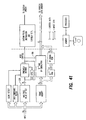
- Fig. 41 is a block diagram of a circuit for receiving a 10-bit gamma corrected video signal. All modes described earlier for the 8-bit circuit in Fig. 40 can be applied using a 10-bit input. The major difference in the hardware is that the inverse-gamma correction and sustain pulse coding read only memory (ROM) 280 for the 10-bit system must be 4 times deeper to accommodate the 2 additional address (input data) bits. For simplicity, the maximum pixel value detector 230 truncates 2 LSBs before determining the maximum pixel value from 8 bits as described above.
- ROM read only memory
Landscapes
- Engineering & Computer Science (AREA)
- Physics & Mathematics (AREA)
- Computer Hardware Design (AREA)
- General Physics & Mathematics (AREA)
- Theoretical Computer Science (AREA)
- Power Engineering (AREA)
- Plasma & Fusion (AREA)
- Control Of Indicators Other Than Cathode Ray Tubes (AREA)
- Transforming Electric Information Into Light Information (AREA)
- Control Of Gas Discharge Display Tubes (AREA)
Applications Claiming Priority (2)
| Application Number | Priority Date | Filing Date | Title |
|---|---|---|---|
| US09/452,970 US6396508B1 (en) | 1999-12-02 | 1999-12-02 | Dynamic low-level enhancement and reduction of moving picture disturbance for a digital display |
| US452970 | 1999-12-02 |
Publications (2)
| Publication Number | Publication Date |
|---|---|
| EP1107219A2 true EP1107219A2 (fr) | 2001-06-13 |
| EP1107219A3 EP1107219A3 (fr) | 2001-09-12 |
Family
ID=23798708
Family Applications (1)
| Application Number | Title | Priority Date | Filing Date |
|---|---|---|---|
| EP00310732A Withdrawn EP1107219A3 (fr) | 1999-12-02 | 2000-12-04 | Amelioration dynamique d'un image de lumiere residuelle pour un panneau d'affichage à plasma |
Country Status (6)
| Country | Link |
|---|---|
| US (1) | US6396508B1 (fr) |
| EP (1) | EP1107219A3 (fr) |
| JP (1) | JP2001222254A (fr) |
| KR (1) | KR20010062092A (fr) |
| CN (1) | CN1214355C (fr) |
| TW (1) | TW501085B (fr) |
Cited By (3)
| Publication number | Priority date | Publication date | Assignee | Title |
|---|---|---|---|---|
| KR20010062092A (ko) * | 1999-12-02 | 2001-07-07 | 모리시타 요이찌 | 디지털 표시를 위한 동적 저-레벨의 향상 및 동화상외란의 감소 |
| EP1587055A3 (fr) * | 2004-04-16 | 2009-04-22 | Hitachi Plasma Display Limited | Dispositif d'affichage à plasma |
| TWI413095B (zh) * | 2008-09-19 | 2013-10-21 | Innolux Corp | 影像強化單元、顯示面板、顯示裝置及影像強化方法 |
Families Citing this family (56)
| Publication number | Priority date | Publication date | Assignee | Title |
|---|---|---|---|---|
| US6674446B2 (en) * | 1999-12-17 | 2004-01-06 | Koninilijke Philips Electronics N.V. | Method of and unit for displaying an image in sub-fields |
| US6639605B2 (en) * | 1999-12-17 | 2003-10-28 | Koninklijke Philips Electronics N.V. | Method of and unit for displaying an image in sub-fields |
| US20010030511A1 (en) * | 2000-04-18 | 2001-10-18 | Shunpei Yamazaki | Display device |
| JP3767791B2 (ja) * | 2000-04-18 | 2006-04-19 | パイオニア株式会社 | ディスプレイパネルの駆動方法 |
| JP2003533715A (ja) * | 2000-05-09 | 2003-11-11 | コーニンクレッカ フィリップス エレクトロニクス エヌ ヴィ | 画像をサブフィールドで表示する方法及びユニット |
| TW512304B (en) * | 2000-06-13 | 2002-12-01 | Semiconductor Energy Lab | Display device |
| JP3556163B2 (ja) * | 2000-09-25 | 2004-08-18 | 富士通日立プラズマディスプレイ株式会社 | 表示装置 |
| US6791516B2 (en) * | 2001-01-18 | 2004-09-14 | Lg Electronics Inc. | Method and apparatus for providing a gray level in a plasma display panel |
| DE10112622A1 (de) * | 2001-03-14 | 2002-09-19 | Grundig Ag | Verfahren und Vorrichtung zur Verbesserung der Grauwertauflösung einer pulsbreitengesteuerten Bildanzeigevorrichtung |
| TW582000B (en) * | 2001-04-20 | 2004-04-01 | Semiconductor Energy Lab | Display device and method of driving a display device |
| JP2002328648A (ja) * | 2001-04-26 | 2002-11-15 | Nec Corp | Ac型プラズマディスプレイパネルの駆動方法および駆動装置 |
| JP4610793B2 (ja) * | 2001-06-08 | 2011-01-12 | パナソニック株式会社 | 表示装置及び方法 |
| JP4507470B2 (ja) * | 2001-07-13 | 2010-07-21 | 株式会社日立製作所 | プラズマディスプレイパネル表示装置 |
| JP4011320B2 (ja) * | 2001-10-01 | 2007-11-21 | 株式会社半導体エネルギー研究所 | 表示装置及びそれを用いた電子機器 |
| WO2003046871A1 (fr) * | 2001-11-21 | 2003-06-05 | Silicon Display Incorporated | Procede et systeme de commande d'un pixel au moyen de chaines d'impulsions simples |
| EP1329869A1 (fr) * | 2002-01-16 | 2003-07-23 | Deutsche Thomson-Brandt Gmbh | Procédé et dispositif de traitement d'images vidéo, |
| KR20040079945A (ko) * | 2002-01-23 | 2004-09-16 | 코닌클리즈케 필립스 일렉트로닉스 엔.브이. | 디스플레이 패널의 셀 어드레싱 방법 및 장치 |
| JP2003271099A (ja) * | 2002-03-13 | 2003-09-25 | Semiconductor Energy Lab Co Ltd | 表示装置および表示装置の駆動方法 |
| JP2004021181A (ja) * | 2002-06-20 | 2004-01-22 | Nec Corp | プラズマディスプレイパネルの駆動方法 |
| US6784898B2 (en) * | 2002-11-07 | 2004-08-31 | Duke University | Mixed mode grayscale method for display system |
| TWI359394B (en) * | 2002-11-14 | 2012-03-01 | Semiconductor Energy Lab | Display device and driving method of the same |
| CN100485462C (zh) * | 2003-06-11 | 2009-05-06 | 友达光电股份有限公司 | 液晶显示器驱动装置及方法 |
| JP4117615B2 (ja) * | 2003-06-30 | 2008-07-16 | ソニー株式会社 | 一時蓄積管理装置、一時蓄積管理方法及び一時蓄積管理プログラム |
| US7580033B2 (en) | 2003-07-16 | 2009-08-25 | Honeywood Technologies, Llc | Spatial-based power savings |
| US7714831B2 (en) * | 2003-07-16 | 2010-05-11 | Honeywood Technologies, Llc | Background plateau manipulation for display device power conservation |
| US7583260B2 (en) * | 2003-07-16 | 2009-09-01 | Honeywood Technologies, Llc | Color preservation for spatially varying power conservation |
| US7786988B2 (en) | 2003-07-16 | 2010-08-31 | Honeywood Technologies, Llc | Window information preservation for spatially varying power conservation |
| US7663597B2 (en) * | 2003-07-16 | 2010-02-16 | Honeywood Technologies, Llc | LCD plateau power conservation |
| US20060020906A1 (en) * | 2003-07-16 | 2006-01-26 | Plut William J | Graphics preservation for spatially varying display device power conversation |
| US7602388B2 (en) * | 2003-07-16 | 2009-10-13 | Honeywood Technologies, Llc | Edge preservation for spatially varying power conservation |
| KR100508937B1 (ko) * | 2003-08-05 | 2005-08-17 | 삼성에스디아이 주식회사 | 고효율 플라즈마 디스플레이 패널에서의 계조 표현 방법및 그 방법을 사용한 플라즈마 디스플레이 패널 구동 장치 |
| KR100599746B1 (ko) * | 2003-10-16 | 2006-07-12 | 삼성에스디아이 주식회사 | 플라즈마 디스플레이 패널의 구동 장치 및 그 계조 표현방법 |
| KR20050049668A (ko) * | 2003-11-22 | 2005-05-27 | 삼성에스디아이 주식회사 | 플라즈마 디스플레이 패널 구동방법 |
| KR100603312B1 (ko) * | 2003-11-24 | 2006-07-20 | 삼성에스디아이 주식회사 | 플라즈마 디스플레이 패널 구동방법 |
| JP2005173387A (ja) * | 2003-12-12 | 2005-06-30 | Nec Corp | 画像処理方法、表示装置の駆動方法及び表示装置 |
| JP4834295B2 (ja) * | 2004-01-09 | 2011-12-14 | 株式会社東芝 | 映像表示装置および映像表示方法 |
| US8194006B2 (en) | 2004-08-23 | 2012-06-05 | Semiconductor Energy Laboratory Co., Ltd. | Display device, driving method of the same, and electronic device comprising monitoring elements |
| JP4563787B2 (ja) * | 2004-12-10 | 2010-10-13 | 日立プラズマディスプレイ株式会社 | プラズマディスプレイ装置及びその制御方法 |
| US7169920B2 (en) * | 2005-04-22 | 2007-01-30 | Xerox Corporation | Photoreceptors |
| EP1720149A3 (fr) * | 2005-05-02 | 2007-06-27 | Semiconductor Energy Laboratory Co., Ltd. | Dispositif d'affichage |
| CN102394049B (zh) * | 2005-05-02 | 2015-04-15 | 株式会社半导体能源研究所 | 显示装置的驱动方法 |
| US7760210B2 (en) * | 2005-05-04 | 2010-07-20 | Honeywood Technologies, Llc | White-based power savings |
| US7602408B2 (en) * | 2005-05-04 | 2009-10-13 | Honeywood Technologies, Llc | Luminance suppression power conservation |
| EP1724751B1 (fr) * | 2005-05-20 | 2013-04-10 | Semiconductor Energy Laboratory Co., Ltd. | Dispositif d'affichage à cristaux liquides et appareil électronique |
| US8059109B2 (en) * | 2005-05-20 | 2011-11-15 | Semiconductor Energy Laboratory Co., Ltd. | Display device and electronic apparatus |
| US7636078B2 (en) * | 2005-05-20 | 2009-12-22 | Semiconductor Energy Laboratory Co., Ltd. | Display device and electronic device |
| KR100705807B1 (ko) * | 2005-06-13 | 2007-04-09 | 엘지전자 주식회사 | 플라즈마 디스플레이 장치 및 그의 구동 방법 |
| TWI272838B (en) * | 2005-06-30 | 2007-02-01 | Sony Taiwan Ltd | Zebra pattern display apparatus |
| JP5013698B2 (ja) * | 2005-10-21 | 2012-08-29 | ローム株式会社 | 2波長型半導体レーザ発光装置及びその製造方法 |
| US20080278412A1 (en) * | 2007-05-09 | 2008-11-13 | Chunghwa Picture Tubes, Ltd. | Circuit and method for adjusting gray scale of plasma display panel |
| EP2006829A1 (fr) * | 2007-06-18 | 2008-12-24 | Deutsche Thomson OHG | Procédé et dispositif pour coder des niveaux vidéo dans un mot de code de sous-trame |
| CN101441849B (zh) * | 2007-11-23 | 2012-02-29 | 四川虹欧显示器件有限公司 | 降低ac-pdp的图像动态伪轮廓的方法及系统 |
| CN101908313B (zh) * | 2010-08-02 | 2012-10-17 | 福州大学 | 多路脉宽调制数字显示系统功率动态均衡的方法及装置 |
| KR20150048394A (ko) * | 2013-10-28 | 2015-05-07 | 삼성디스플레이 주식회사 | 휘도 보정 시스템 |
| KR102509533B1 (ko) | 2014-02-25 | 2023-03-14 | 애플 인크. | 비디오 인코딩 및 디코딩을 위한 적응형 전달 함수 |
| WO2018053007A1 (fr) * | 2016-09-19 | 2018-03-22 | Apple Inc. | Commande de taux d'émission d'afficheurs numériques |
Citations (2)
| Publication number | Priority date | Publication date | Assignee | Title |
|---|---|---|---|---|
| JPH10107573A (ja) | 1996-09-30 | 1998-04-24 | Kyocera Corp | 弾性表面波装置 |
| JPH10153980A (ja) | 1996-11-22 | 1998-06-09 | Matsushita Electric Ind Co Ltd | 画像表示装置 |
Family Cites Families (14)
| Publication number | Priority date | Publication date | Assignee | Title |
|---|---|---|---|---|
| JP3891499B2 (ja) * | 1995-04-14 | 2007-03-14 | パイオニア株式会社 | プラズマディスプレイパネルにおける輝度調整装置 |
| JP3660018B2 (ja) | 1995-05-17 | 2005-06-15 | 株式会社アルバック | 真空装置の異常放電消滅装置 |
| JPH10171403A (ja) * | 1996-12-13 | 1998-06-26 | Victor Co Of Japan Ltd | プラズマディスプレイパネル表示装置の駆動方法 |
| JP3167632B2 (ja) | 1996-12-16 | 2001-05-21 | 大阪瓦斯株式会社 | 温度調整方法 |
| JPH10207426A (ja) * | 1997-01-21 | 1998-08-07 | Victor Co Of Japan Ltd | プラズマディスプレイパネル表示装置の駆動方法及び駆動制御装置 |
| JP3559135B2 (ja) * | 1997-01-30 | 2004-08-25 | パイオニア株式会社 | プラズマディスプレイパネルの駆動方法 |
| JP4023524B2 (ja) * | 1997-04-09 | 2007-12-19 | 株式会社日立プラズマパテントライセンシング | 階調表示方法 |
| JPH1165521A (ja) * | 1997-08-20 | 1999-03-09 | Fujitsu General Ltd | ディスプレイの駆動方式 |
| JP3458996B2 (ja) * | 1997-08-21 | 2003-10-20 | 日本ビクター株式会社 | プラズマディスプレイパネル表示装置及びその駆動方法 |
| FR2769743B1 (fr) | 1997-10-09 | 2000-01-07 | Thomson Multimedia Sa | Procede et dispositif de balayage d'un panneau a plasma |
| JPH11119730A (ja) * | 1997-10-20 | 1999-04-30 | Hitachi Ltd | 映像表示装置 |
| JP2994630B2 (ja) * | 1997-12-10 | 1999-12-27 | 松下電器産業株式会社 | 明るさによるサブフィールド数調整可能な表示装置 |
| JP2994631B2 (ja) * | 1997-12-10 | 1999-12-27 | 松下電器産業株式会社 | Pdp表示の駆動パルス制御装置 |
| US6396508B1 (en) * | 1999-12-02 | 2002-05-28 | Matsushita Electronics Corp. | Dynamic low-level enhancement and reduction of moving picture disturbance for a digital display |
-
1999
- 1999-12-02 US US09/452,970 patent/US6396508B1/en not_active Expired - Lifetime
-
2000
- 2000-12-01 CN CNB001281003A patent/CN1214355C/zh not_active Expired - Fee Related
- 2000-12-01 TW TW089125632A patent/TW501085B/zh not_active IP Right Cessation
- 2000-12-02 KR KR1020000072688A patent/KR20010062092A/ko not_active Ceased
- 2000-12-04 EP EP00310732A patent/EP1107219A3/fr not_active Withdrawn
- 2000-12-04 JP JP2000367910A patent/JP2001222254A/ja active Pending
Patent Citations (2)
| Publication number | Priority date | Publication date | Assignee | Title |
|---|---|---|---|---|
| JPH10107573A (ja) | 1996-09-30 | 1998-04-24 | Kyocera Corp | 弾性表面波装置 |
| JPH10153980A (ja) | 1996-11-22 | 1998-06-09 | Matsushita Electric Ind Co Ltd | 画像表示装置 |
Cited By (3)
| Publication number | Priority date | Publication date | Assignee | Title |
|---|---|---|---|---|
| KR20010062092A (ko) * | 1999-12-02 | 2001-07-07 | 모리시타 요이찌 | 디지털 표시를 위한 동적 저-레벨의 향상 및 동화상외란의 감소 |
| EP1587055A3 (fr) * | 2004-04-16 | 2009-04-22 | Hitachi Plasma Display Limited | Dispositif d'affichage à plasma |
| TWI413095B (zh) * | 2008-09-19 | 2013-10-21 | Innolux Corp | 影像強化單元、顯示面板、顯示裝置及影像強化方法 |
Also Published As
| Publication number | Publication date |
|---|---|
| TW501085B (en) | 2002-09-01 |
| CN1304128A (zh) | 2001-07-18 |
| CN1214355C (zh) | 2005-08-10 |
| JP2001222254A (ja) | 2001-08-17 |
| EP1107219A3 (fr) | 2001-09-12 |
| KR20010062092A (ko) | 2001-07-07 |
| US6396508B1 (en) | 2002-05-28 |
Similar Documents
| Publication | Publication Date | Title |
|---|---|---|
| US6396508B1 (en) | Dynamic low-level enhancement and reduction of moving picture disturbance for a digital display | |
| CN100452851C (zh) | 处理视频图像的方法和装置 | |
| US6100863A (en) | Motion pixel distortion reduction for digital display devices using dynamic programming coding | |
| EP0884717B1 (fr) | Méthode et appareil pour corriger la distorsion d'image d'un panneau d'affichage à plasma utilisant un codage à distance minimale MPD | |
| KR100454786B1 (ko) | 텔레비젼화상신호의계조표시방법및그장치 | |
| EP0811963B1 (fr) | Dispositif d'affichage d'image par plasma et son procédé de commande | |
| KR100898668B1 (ko) | 디스플레이 디바이스를 제어하기 위한 방법 및 장치 | |
| EP1437705A1 (fr) | Procédé pour optimiser la luminosité dans un dispositif d' affichage et dispositif pour la mise en oeuvre de ce procédé | |
| CN1241014A (zh) | 使用脉冲数均衡法减小数字式显示器的运动象素失真 | |
| CN1203461C (zh) | 以子场显示图像的方法和装置 | |
| CN1187728C (zh) | 用于在子场中显示图像的方法和单元 | |
| KR20010102227A (ko) | 서브 필드들에 이미지를 디스플레이하는 방법 및 유니트 | |
| US20080158265A1 (en) | Method and device for multi-grayscale display | |
| KR101077251B1 (ko) | 허위 윤곽선 및 디더링 잡음 보상을 위한 비디오 화상 처리 방법 | |
| JP5146933B2 (ja) | ビデオ映像を処理する方法および装置 | |
| JP2003140605A (ja) | プラズマ表示装置及びその駆動方法 | |
| EP1437706A2 (fr) | Procédé pour optimiser la luminosité dans un dispositif d' affichage et dispositif pour la mise en oeuvre de ce procédé | |
| EP1936590B1 (fr) | Procédé et dispositif de traitement d'images vidéo | |
| JP5101886B2 (ja) | 特定の境界符号化を用いることによってビデオ・データを処理する方法及び装置 | |
| JP4393157B2 (ja) | 色温度変化補償方法、画像表示方法、及びプラズマ表示装置 | |
| EP1335341A2 (fr) | Procédé et appareil pour le traitement d'images vidéo | |
| JP2003157046A (ja) | プラズマ表示装置及びその駆動方法 |
Legal Events
| Date | Code | Title | Description |
|---|---|---|---|
| PUAI | Public reference made under article 153(3) epc to a published international application that has entered the european phase |
Free format text: ORIGINAL CODE: 0009012 |
|
| AK | Designated contracting states |
Kind code of ref document: A2 Designated state(s): DE FR GB Kind code of ref document: A2 Designated state(s): AT BE CH CY DE DK ES FI FR GB GR IE IT LI LU MC NL PT SE TR |
|
| AX | Request for extension of the european patent |
Free format text: AL;LT;LV;MK;RO;SI |
|
| PUAL | Search report despatched |
Free format text: ORIGINAL CODE: 0009013 |
|
| AK | Designated contracting states |
Kind code of ref document: A3 Designated state(s): AT BE CH CY DE DK ES FI FR GB GR IE IT LI LU MC NL PT SE TR |
|
| AX | Request for extension of the european patent |
Free format text: AL;LT;LV;MK;RO;SI |
|
| 17P | Request for examination filed |
Effective date: 20011224 |
|
| AKX | Designation fees paid |
Free format text: DE FR GB |
|
| RAP1 | Party data changed (applicant data changed or rights of an application transferred) |
Owner name: PANASONIC CORPORATION |
|
| STAA | Information on the status of an ep patent application or granted ep patent |
Free format text: STATUS: THE APPLICATION IS DEEMED TO BE WITHDRAWN |
|
| 18D | Application deemed to be withdrawn |
Effective date: 20090317 |