EP1107404A1 - Diode laser stabilisée par un réseau sur une fibre - Google Patents
Diode laser stabilisée par un réseau sur une fibre Download PDFInfo
- Publication number
- EP1107404A1 EP1107404A1 EP01103972A EP01103972A EP1107404A1 EP 1107404 A1 EP1107404 A1 EP 1107404A1 EP 01103972 A EP01103972 A EP 01103972A EP 01103972 A EP01103972 A EP 01103972A EP 1107404 A1 EP1107404 A1 EP 1107404A1
- Authority
- EP
- European Patent Office
- Prior art keywords
- fibre
- grating
- longitudinal
- optical
- bandwidth
- Prior art date
- Legal status (The legal status is an assumption and is not a legal conclusion. Google has not performed a legal analysis and makes no representation as to the accuracy of the status listed.)
- Granted
Links
Images

Classifications
-
- G—PHYSICS
- G02—OPTICS
- G02B—OPTICAL ELEMENTS, SYSTEMS OR APPARATUS
- G02B6/00—Light guides; Structural details of arrangements comprising light guides and other optical elements, e.g. couplings
- G02B6/02—Optical fibres with cladding with or without a coating
- G02B6/02057—Optical fibres with cladding with or without a coating comprising gratings
- G02B6/02076—Refractive index modulation gratings, e.g. Bragg gratings
-
- H—ELECTRICITY
- H01—ELECTRIC ELEMENTS
- H01S—DEVICES USING THE PROCESS OF LIGHT AMPLIFICATION BY STIMULATED EMISSION OF RADIATION [LASER] TO AMPLIFY OR GENERATE LIGHT; DEVICES USING STIMULATED EMISSION OF ELECTROMAGNETIC RADIATION IN WAVE RANGES OTHER THAN OPTICAL
- H01S5/00—Semiconductor lasers
- H01S5/10—Construction or shape of the optical resonator, e.g. extended or external cavity, coupled cavities, bent-guide, varying width, thickness or composition of the active region
- H01S5/14—External cavity lasers
- H01S5/146—External cavity lasers using a fiber as external cavity
-
- G—PHYSICS
- G02—OPTICS
- G02B—OPTICAL ELEMENTS, SYSTEMS OR APPARATUS
- G02B6/00—Light guides; Structural details of arrangements comprising light guides and other optical elements, e.g. couplings
- G02B6/02—Optical fibres with cladding with or without a coating
- G02B6/02057—Optical fibres with cladding with or without a coating comprising gratings
-
- H—ELECTRICITY
- H01—ELECTRIC ELEMENTS
- H01S—DEVICES USING THE PROCESS OF LIGHT AMPLIFICATION BY STIMULATED EMISSION OF RADIATION [LASER] TO AMPLIFY OR GENERATE LIGHT; DEVICES USING STIMULATED EMISSION OF ELECTROMAGNETIC RADIATION IN WAVE RANGES OTHER THAN OPTICAL
- H01S2301/00—Functional characteristics
- H01S2301/02—ASE (amplified spontaneous emission), noise; Reduction thereof
-
- H—ELECTRICITY
- H01—ELECTRIC ELEMENTS
- H01S—DEVICES USING THE PROCESS OF LIGHT AMPLIFICATION BY STIMULATED EMISSION OF RADIATION [LASER] TO AMPLIFY OR GENERATE LIGHT; DEVICES USING STIMULATED EMISSION OF ELECTROMAGNETIC RADIATION IN WAVE RANGES OTHER THAN OPTICAL
- H01S3/00—Lasers, i.e. devices using stimulated emission of electromagnetic radiation in the infrared, visible or ultraviolet wave range
- H01S3/05—Construction or shape of optical resonators; Accommodation of active medium therein; Shape of active medium
- H01S3/08—Construction or shape of optical resonators or components thereof
- H01S3/081—Construction or shape of optical resonators or components thereof comprising three or more reflectors
- H01S3/082—Construction or shape of optical resonators or components thereof comprising three or more reflectors defining a plurality of resonators, e.g. for mode selection or suppression
- H01S3/0823—Construction or shape of optical resonators or components thereof comprising three or more reflectors defining a plurality of resonators, e.g. for mode selection or suppression incorporating a dispersive element, e.g. a prism for wavelength selection
- H01S3/0826—Construction or shape of optical resonators or components thereof comprising three or more reflectors defining a plurality of resonators, e.g. for mode selection or suppression incorporating a dispersive element, e.g. a prism for wavelength selection using a diffraction grating
-
- H—ELECTRICITY
- H01—ELECTRIC ELEMENTS
- H01S—DEVICES USING THE PROCESS OF LIGHT AMPLIFICATION BY STIMULATED EMISSION OF RADIATION [LASER] TO AMPLIFY OR GENERATE LIGHT; DEVICES USING STIMULATED EMISSION OF ELECTROMAGNETIC RADIATION IN WAVE RANGES OTHER THAN OPTICAL
- H01S5/00—Semiconductor lasers
- H01S5/06—Arrangements for controlling the laser output parameters, e.g. by operating on the active medium
- H01S5/065—Mode locking; Mode suppression; Mode selection ; Self pulsating
- H01S5/0656—Seeding, i.e. an additional light input is provided for controlling the laser modes, for example by back-reflecting light from an external optical component
-
- H—ELECTRICITY
- H01—ELECTRIC ELEMENTS
- H01S—DEVICES USING THE PROCESS OF LIGHT AMPLIFICATION BY STIMULATED EMISSION OF RADIATION [LASER] TO AMPLIFY OR GENERATE LIGHT; DEVICES USING STIMULATED EMISSION OF ELECTROMAGNETIC RADIATION IN WAVE RANGES OTHER THAN OPTICAL
- H01S5/00—Semiconductor lasers
- H01S5/06—Arrangements for controlling the laser output parameters, e.g. by operating on the active medium
- H01S5/065—Mode locking; Mode suppression; Mode selection ; Self pulsating
- H01S5/0657—Mode locking, i.e. generation of pulses at a frequency corresponding to a roundtrip in the cavity
-
- H—ELECTRICITY
- H01—ELECTRIC ELEMENTS
- H01S—DEVICES USING THE PROCESS OF LIGHT AMPLIFICATION BY STIMULATED EMISSION OF RADIATION [LASER] TO AMPLIFY OR GENERATE LIGHT; DEVICES USING STIMULATED EMISSION OF ELECTROMAGNETIC RADIATION IN WAVE RANGES OTHER THAN OPTICAL
- H01S5/00—Semiconductor lasers
- H01S5/10—Construction or shape of the optical resonator, e.g. extended or external cavity, coupled cavities, bent-guide, varying width, thickness or composition of the active region
- H01S5/14—External cavity lasers
- H01S5/141—External cavity lasers using a wavelength selective device, e.g. a grating or etalon
-
- H—ELECTRICITY
- H01—ELECTRIC ELEMENTS
- H01S—DEVICES USING THE PROCESS OF LIGHT AMPLIFICATION BY STIMULATED EMISSION OF RADIATION [LASER] TO AMPLIFY OR GENERATE LIGHT; DEVICES USING STIMULATED EMISSION OF ELECTROMAGNETIC RADIATION IN WAVE RANGES OTHER THAN OPTICAL
- H01S5/00—Semiconductor lasers
- H01S5/40—Arrangement of two or more semiconductor lasers, not provided for in groups H01S5/02 - H01S5/30
- H01S5/4025—Array arrangements, e.g. constituted by discrete laser diodes or laser bar
Definitions
- the present invention is a stabilized laser source which provides narrow-bandwidth high-power optical radiation with stable intensity and wavelength suitable, for example, for optically pumping solid-state fibre amplifiers or lasers such as fibre lasers.
- Optical fibre amplifiers and lasers have rapidly become important components of optical communications systems.
- Optical fibre amplifiers are used to intensify optical signals that are attenuated along the fibre-optic communication path. They have replaced cumbersome electrical repeaters in fibre-optic communication links allowing true all-fibre optical communications systems to be realized.
- optical fibre lasers have been proposed to generate an optical carrier for fibre-optic communications systems. These lasers can be externally modulated or mode locked, and in some cases are an alternative to diode lasers as sources of high-power light in fibre optic communications systems.
- the silica glass in the guided-wave portion of the optical fibre is doped with ions of a rare-earth element such as, for example, erbium.
- the energy structure of the erbium ions is such that signal light with wavelength of approximately 1530-1565 nm can be amplified in the fibre if the population of the excited states of the erbium ions is such that rate of stimulated emission exceeds that of spontaneous emission and absorption. In such a circumstance, light within the gain bandwidth entering the optical fibre will experience net gain, and will exit the fibre with greater power.
- the diode lasers are permanently and robustly connected with an optomechanical apparatus to a length of undoped optical fibre which in turn is connected to the doped fibre in the optical amplifier or laser.
- the assembly consisting of the diode laser, optomechanical apparatus and optical fibre is called a pigtailed diode laser.
- many pigtailed diode lasers have undesirable characteristics such as wavelength and intensity instabilities that create noise in the pumped system.
- the most troublesome sources of diode laser noise in 980 nm diode lasers are mode-hopping noise and wavelength fluctuations that are caused by unwanted variable optical feedback into the diode laser or changes in temperature or injection current. The noise is especially detrimental in fibre amplifiers because it increases errors in the amplified optical communication signal and detracts from the practicality of these devices.
- Feedback is usually provided by an external reflector such as a mirror or diffraction grating, and external optical elements such as lenses are required to manipulate and guide the light out of and back into the diode laser cavity.
- an external reflector such as a mirror or diffraction grating
- external optical elements such as lenses are required to manipulate and guide the light out of and back into the diode laser cavity.
- the external optics and reflectors can often be quite compact, it is difficult and expensive to align such a system, and the mechanical and thermal stability can often be inadequate for use in fibre amplifiers and lasers. A more rugged technique for control of diode laser characteristics is required.
- the present invention uses a fibre Bragg grating in a pigtailed diode laser to provide optical feedback into the cavity of a diode laser, thereby locking the frequency of the diode laser to that of the fibre grating, and reducing the longitudinal mode-hopping noise of the laser.
- a fibre Bragg grating is a periodic structure of refractive index variations in or near the guided-mode portion of the optical fibre that can reflect light of a certain wavelength propagating along the fibre. The reflected light propagates in the fibre in a direction opposite to that of the incident light.
- a diode laser is pigtailed to a fibre containing a fibre Bragg grating, and if the centre of the grating bandwidth is within the gain bandwidth of the laser, then the optical spectrum of the diode laser will be affected. The exact effect depends on such parameters as the magnitude and bandwidth of the grating reflectivity, the centre wavelength of the grating relative to the laser, the magnitude of separation between the laser and grating, and the magnitude of injection current into the diode laser. In many cases, the laser characteristics can be improved for a given application.
- the apparatus according to the invention is formed by a diode laser, means for focusing the emission of the laser into a length of optical fibre, and a fibre grating formed in or near the guided wave portion of the optical fibre.
- the invention consists of apparatus for generating a stable laser source having multiple longitudinal modes across a very narrow bandwidth.
- the apparatus comprises a diode laser that emits light in substantially a single spatial mode.
- An optical fibre is provided which is capable of guiding at least one mode of the diode laser in a portion of the fibre.
- Means are provided for directing the emitted light from the diode laser into a polarization-maintaining optical fibre.
- a fibre Bragg grating is formed in the region of the guided mode portion of the optical fibre.
- an apparatus for generating a stable laser source having multiple longitudinal modes comprises: a diode laser that emits light in substantially a single spatial mode and which includes a diode lasing cavity and an output facet defining an end of the diode lasing cavity, and which lases in multiple longitudinal modes within the lasing cavity in the absence of external optical feedback; an optical fibre including a guided wave portion of the fibre which is capable of sustaining at least one mode at the wavelength of the diode laser; means for directing the emitted light from the diode laser into the optical fibre; a fibre Bragg grating in the guided wave portion of the fibre and having a reflection bandwidth; and, said output facet having a reflectivity approximately equal to or greater than that of the fibre Bragg grating, wherein the reflected light from the fibre Bragg grating into the diode lasing cavity limits the bandwidth of lasing to a value less than or equal to the reflection bandwidth of the grating and induces lasing in multiple longitudinal modes of the external cavity formed
- a pigtailed diode laser for producing multiple longitudinal modes comprises: a diode laser that emits light in substantially a single spatial mode and which includes a diode lasing cavity and an output facet defining an end of the diode lasing cavity, and which lases in multiple longitudinal modes within the lasing cavity in the absence of external optical feedback; an optical fibre including a guided wave portion of the fibre which is capable of sustaining at least one mode at the wavelength of the diode laser; means for directing the emitted light from the diode laser into the optical fibre; a fibre Bragg grating in the guided wave portion of the fibre and having a reflection bandwidth; and, said output facet having a reflectivity approximately equal to or greater than that of the fibre Bragg grating, wherein the reflected light from the fibre Bragg grating into the diode lasing cavity limits the bandwidth of lasing to a value less than or equal to the reflection bandwidth of the grating and induces lasing in multiple longitudinal modes of the external cavity
- said means for directing comprises focusing means.
- said focusing means comprises lens means.
- said means for directing comprises positioning the optical fibre in close proximity to the diode laser exit facet such that a substantial portion of the light emitted from the diode laser is collected by the fibre.
- fibre Bragg grating is etched in the region of the guided mode portion of the optical fibre.
- the reflectivity and reflective wavelength of the fibre Bragg grating is selected such that the broadband feedback of the diode laser cavity is greater than the feedback from the fibre Bragg grating.
- the fibre Bragg grating has a maximum reflectivity within 10 nm of the diode laser emission wavelength and the bandwidth of the grating reflectivity is between 0.05 nm and 2 nm.
- the wavelength of maximum reflectivity of the fibre Bragg grating is within the gain bandwidth of the diode laser.
- the optical fibre is low bi-refringent optical fibre;
- the diode laser is a strained layer In-Ga-As multiquantum well diode laser;
- the lens means are anspheric lens; and
- the fibre Bragg grating has a reflection bandwidth of 0.05 nm to 1 nm.
- the diode laser emits substantially coherent light at a wavelength of 960-1160 nm.
- the optical distance between the exit facet of the diode laser and the fibre Bragg grating is more than the coherence length of the optical output of the diode laser.
- an apparatus for generating a stable laser source having single longitudinal mode line width operation comprises: a diode laser that emits light in substantially a single spatial mode and which includes a diode lasing cavity and an output facet defining an end of the diode lasing cavity, and which lases in multiple longitudinal modes within the lasing cavity in the absence of external optical feedback; an optical fibre including a guided wave portion of the fibre which is capable of sustaining at least one mode at the wavelength of the diode laser; means for directing the emitted light from the diode laser into the optical fibre; a fibre Bragg grating in the guided wave portion of the fibre and having a reflection bandwidth; and, said output facet having a reflectivity approximately equal to or greater than that of the fibre Bragg grating, and wherein the optical distance between the exit facet of the diode laser and the fibre Bragg grating is less than the coherence length of the optical output of the diode laser, wherein the reflected light from the fibre Bragg grating into
- the fibre Bragg grating is formed by exposure to ultraviolet light in the region of the guided mode portion of the optical fibre.
- optical fibre is polarization-maintaining optical fibre.
- Fig. 1 represents a fibre amplifier 10 including a pigtailed diode laser according to the prior art.
- Optical fibre 14 is doped with erbium (indicated by numerals 16) to provide amplifying effect and is coupled to undoped fibre 13.
- the amplifying effect may be achieved by exciting the erbium atoms with light at about 980 nm. This is achieved by coupling a 980 nm light source to the transmission light (at 1550 nm) from the transmission fibre 5 by means of an optoelectronic coupler 18.
- the 980 nm light source is provided in the prior art by a pigtailed laser diode 20 consisting of a laser diode 22 coupled by lens 23 to undoped fibre 24.
- a pigtailed laser diode 20 consisting of a laser diode 22 coupled by lens 23 to undoped fibre 24.
- the limitations of prior art pigtailed laser diodes have been discussed above.
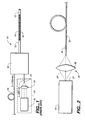
- Fig. 2 illustrates a pigtailed laser diode according to the preferred embodiment of the invention.
- Diode laser 26 emits radiation in a single-spatial mode, and is typically fabricated with a quantum well epitaxial structure or index guided structure from InGaAs semiconductor material. The diode laser is most conveniently pumped by current injection. Diode lasers with the necessary characteristics are commercially available.
- the diode laser 26 is configured to emit radiation primarily from the front facet 27.
- the divergent laser emission 28 is directed with focusing system 30 into the guided-mode portion of a length of optical fibre 32, containing an intra-core fibre Bragg grating 34.
- the focusing system of the preferred embodiment consists of a lensing system represented as numeral 36 to focus the laser diode output into the fibre 32.
- the fibre can be placed in such proximity to the diode laser that a substantial fraction of the emitted light is collected by the fibre.
- the optical fibre 32 is typically fabricated from silica glass containing trace dopants to improve the light guiding characteristics of the fibre.
- the fibre grating 34 that provides optical feedback to the diode laser can be etched near the guided-mode portion of the fibre 34 using lithography techniques, or more commonly, can be created by exposing the fibre to a pattern of periodic intensity variation of high fluence ultraviolet light. If the latter technique is employed to fabricate the grating, it is convenient if the fibre core has a concentration of germanium to render the core sensitive to the ultraviolet light that forms the grating.
- the fibre 34 may be one that sustain a single or multiple spatial modes at the wavelength of emission of the diode laser.
- the fibre grating 34 is selected to have maximum reflectivity within 10 nm of the diode laser emission wavelength, and the reflectivity is similar to that of the exit facet of the diode laser.
- the bandwidth of the grating reflectivity is typically 0.05 nm to 1 nm, but can be up to 2 nm.
- the system can operate successfully when the grating 34 and the laser diode 26 are separated by a few hundred micrometers to several kilometres provided the amount of optical feedback into the laser remains greater than a certain magnitude. Using such a configuration, the diode laser has substantially improved characteristics suitable for pumping solid-state amplifiers or lasers.
- the light captured by the fibre 34 would normally propagate down a length of the fibre indefinitely, limited only by the fibre loss characteristics.
- the fibre Bragg grating 34 is fabricated within the guided mode portion or core of this length of fibre.
- the grating is fabricated such that the wavelength of its maximum reflection is within the gain bandwidth of the diode laser. This grating reflects a fraction of the diode laser emission light back through the fibre and the focusing system into the diode laser. The remainder of the light output passes through the fibre grating and down the remaining length of fibre.
- the effect of the fibre grating on the characteristics of the diode laser optical output is explained by considering the wavelength-dependent loss in the coupled cavity formed by the fibre grating.
- the optical feedback from the fibre grating effectively reduces the loss from the laser cavity of light within the bandwidth of the fibre grating.
- the laser can operate preferentially near the wavelength of lowest loss, hence the wavelength of the diode laser can be shifted from its free running value to the wavelength of the fibre grating. This can occur if the wavelength of the fibre grating is within the gain bandwidth of the diode laser, provided the magnitude of reflectivity from the grating is sufficient.
- the behaviour of the diode laser under conditions of optical feedback is complicated by the effect of the diode laser cavity itself, which is formed by the end facets of the semiconductor chip.
- the reflectivity of the grating as well as its wavelength are selected such that the broadband feedback from the diode laser cavity is greater than the feedback from the fibre grating.
- the feedback from the fibre grating acts as a perturbation of the coherent electric field formed in the diode laser cavity. This perturbation acts to break the coherence of the diode laser emission, thus broadening the bandwidth of the emission by several orders of magnitude, resulting in a spectral distribution as shown in curve A of Fig. 3.
- the fibre Bragg grating effectively locks the diode cavity output to the fixed wavelength of the grating and centres the external cavity multi-longitudinal modes around that wavelength.
- the presence of the multi-longitudinal modes reduces the magnitude of mode-hopping noise in the diode laser. This is termed coherence collapse of the diode laser.
- the centre wavelength of emission remains near the wavelength of maximum reflection from the fibre grating.
- the diode laser is thus constrained to operate within the grating bandwidth, so that large fluctuations in wavelength of the diode laser caused by changes in temperature or current are eliminated. Additionally, the laser is not perturbed by extraneous optical feedback from reflective components located beyond the fibre grating, provided the extraneous feedback is less than that provided by the fibre grating.
- a diode laser in accordance with the present invention does not undergo transitions of single longitudinal laser cavity modes as are observed in free-running diode laser. Such transitions cause large intensity fluctuations in the diode laser output caused by competition between two modes during the transition. These mode transitions are caused by changes in laser injection current or temperature, for example, and are detrimental to the operation of an optical amplifier or fibre laser.
- the optical output of the invention consists of twenty or more longitudinal modes of the external cavity. Although the partitioning of optical power between the modes may change, there is much less fluctuation in laser intensity compared to that of a single mode, free-running diode laser.
- the output power from the end of the fibre of the diode laser system is only slightly affected by the presence of the grating in the fibre.
- the output power from the fibre is reduced approximately by (1-R g ), where R g is the maximum reflectivity of the grating.
- the injection current at laser threshold is slightly reduced by the presence of the grating. This effect increases the output power from the fibre and counteracts the aforementioned reduction of power.
- the scope of the invention comprises a system in which the fibre grating is an arbitrary length from the diode laser.
- the magnitude of this length affects the operation of the diode laser.
- the fibre grating is located at a sufficient optical distance from the front facet of the diode laser. This distance must be much longer than the coherence length of the diode laser under the prescribed conditions of optical feedback, so that optical feedback from the fibre grating remains incoherent, thus assuring the laser remains in a state of coherence collapse.
- the feedback from the fibre grating may be coherent with the electric field inside the laser cavity, and very narrow linewidth operation of the diode laser will result.
- Such emission is very useful for some applications but is much less stable for the application of pumping fibre amplifiers or lasers because of the onset of laser cavity-mode transition noise when the laser operating characteristics change.
- there are still transitions from coherent to incoherent operation of the diode laser which cause intensity fluctuations which are detrimental to the operation of optical fibre amplifiers and lasers.
- optical fibre that can maintain the state of polarization of light propagating down the fibre.
- Such fibre has a relatively large amount of controlled, stress-induced birefringence produced near the guided-mode portion upon manufacture. This high-birefringence, or polarization-maintaining optical fibre, is commercially available.
- fibre gratings have been fabricated in several commercially available polarization-maintaining optical fibres and such fibre is easily incorporated into the pigtailed diode laser.
- PandaTM fibre from Fujikura Ltd. was used for fibre 14.
- a Bragg fibre grating was formed in the Panda fibre and was used with good results.
- a strained-layer InGaAs multi-quantum well diode laser is coupled to the optical fibre with an aspheric lens systems with efficiency of 60%.
- the laser emits light at 965-1160 nm, typically.
- the wavelength of the grating reflectivity nominally lies within 10 nm of the wavelength of the diode laser.
- the grating is 1-2 mm in length.
- the fibre grating is located at least 50 cm from the front facet of the diode laser. If it is desirable to maintain the coherence of the laser system, the fibre grating should be located as close as possible to the exit facet of the diode laser, and certainly not more than a few centimetres away.
- the output power from the optical fibre in the preferred embodiment is at most reduced by a few percent.
- the output power from the fibre may exceed 90 Mw which is similar to that from a fibre with no grating, within experimental uncertainty.
- Fig. 3 illustrates the optical output spectrum of the present invention.
- curve B is the output spectrum of a 980 nm InGaAs pigtailed diode laser without a fibre grating. There is approximately 0.5% feedback into the diode laser from a broadband external reflector, which causes destabilization of the laser wavelength.
- the diode laser operates under the same conditions, but there is a fibre grating with a peak reflectivity of 3% and a bandwidth of 0.3 nm.
- the improvement of the output spectrum is clear.
- the output of the invention is stable even when the injection current or temperature of the laser diode are significantly altered. Accordingly, no control of the laser diode temperature is required in some instances, which eliminates the need for a laser cooler and the associated control electronics. The power requirement to control the laser temperature is also suitably reduced.
- the present invention provides a highly stabilized source of high-power optical radiation that will improve the characteristics and stability of optical amplifiers and lasers that must be pumped with such a source.
Landscapes
- Physics & Mathematics (AREA)
- General Physics & Mathematics (AREA)
- Optics & Photonics (AREA)
- Condensed Matter Physics & Semiconductors (AREA)
- Electromagnetism (AREA)
- Semiconductor Lasers (AREA)
- Lasers (AREA)
- Optical Couplings Of Light Guides (AREA)
Applications Claiming Priority (5)
| Application Number | Priority Date | Filing Date | Title |
|---|---|---|---|
| US267785 | 1994-06-28 | ||
| US08/267,785 US5485481A (en) | 1994-06-28 | 1994-06-28 | Fibre-grating-stabilized diode laser |
| US408002 | 1995-03-21 | ||
| US08/408,002 US5659559A (en) | 1994-06-28 | 1995-03-21 | Apparatus for generating a stabilized laser source |
| EP95923153A EP0767979B1 (fr) | 1994-06-28 | 1995-06-28 | Diode laser stabilisee par un reseau sur une fibre |
Related Parent Applications (1)
| Application Number | Title | Priority Date | Filing Date |
|---|---|---|---|
| EP95923153A Division EP0767979B1 (fr) | 1994-06-28 | 1995-06-28 | Diode laser stabilisee par un reseau sur une fibre |
Publications (2)
| Publication Number | Publication Date |
|---|---|
| EP1107404A1 true EP1107404A1 (fr) | 2001-06-13 |
| EP1107404B1 EP1107404B1 (fr) | 2007-12-26 |
Family
ID=26952637
Family Applications (2)
| Application Number | Title | Priority Date | Filing Date |
|---|---|---|---|
| EP95923153A Expired - Lifetime EP0767979B1 (fr) | 1994-06-28 | 1995-06-28 | Diode laser stabilisee par un reseau sur une fibre |
| EP01103972A Expired - Lifetime EP1107404B1 (fr) | 1994-06-28 | 1995-06-28 | Diode laser stabilisée par un réseau sur une fibre |
Family Applications Before (1)
| Application Number | Title | Priority Date | Filing Date |
|---|---|---|---|
| EP95923153A Expired - Lifetime EP0767979B1 (fr) | 1994-06-28 | 1995-06-28 | Diode laser stabilisee par un reseau sur une fibre |
Country Status (7)
| Country | Link |
|---|---|
| US (1) | US5659559A (fr) |
| EP (2) | EP0767979B1 (fr) |
| JP (1) | JP3296562B2 (fr) |
| AU (1) | AU2782795A (fr) |
| CA (1) | CA2191190C (fr) |
| DE (2) | DE69535675T2 (fr) |
| WO (1) | WO1996000997A1 (fr) |
Cited By (1)
| Publication number | Priority date | Publication date | Assignee | Title |
|---|---|---|---|---|
| WO2007132182A3 (fr) * | 2006-05-11 | 2009-05-14 | Spi Lasers Uk Ltd | Appareil de rayonnement optique |
Families Citing this family (38)
| Publication number | Priority date | Publication date | Assignee | Title |
|---|---|---|---|---|
| US5724377A (en) * | 1996-02-29 | 1998-03-03 | Lucent Technologies Inc. | Method and apparatus for improving the instability of a laser |
| US6058128A (en) * | 1996-03-25 | 2000-05-02 | Sdl, Inc. | Apparatus for providing a stabilized laser source |
| JP3120828B2 (ja) * | 1996-04-08 | 2000-12-25 | 住友電気工業株式会社 | 半導体レーザモジュール |
| US5761226A (en) * | 1996-05-29 | 1998-06-02 | Eastman Kodak Company | Frequency conversion laser devices |
| US6052393A (en) | 1996-12-23 | 2000-04-18 | The Regents Of The University Of Michigan | Broadband Sagnac Raman amplifiers and cascade lasers |
| GB9700417D0 (en) * | 1997-01-10 | 1997-02-26 | Renishaw Plc | Low frequency bandwidth laser diode |
| US6374006B1 (en) | 1998-03-20 | 2002-04-16 | Xtera Communications, Inc. | Chirped period gratings for raman amplification in circulator loop cavities |
| US6600592B2 (en) | 1998-03-24 | 2003-07-29 | Xtera Communications, Inc. | S+ band nonlinear polarization amplifiers |
| US6356384B1 (en) * | 1998-03-24 | 2002-03-12 | Xtera Communications Inc. | Broadband amplifier and communication system |
| US6760148B2 (en) | 1998-03-24 | 2004-07-06 | Xtera Communications, Inc. | Nonlinear polarization amplifiers in nonzero dispersion shifted fiber |
| US6574037B2 (en) | 1998-06-16 | 2003-06-03 | Xtera Communications, Inc. | All band amplifier |
| US6335820B1 (en) | 1999-12-23 | 2002-01-01 | Xtera Communications, Inc. | Multi-stage optical amplifier and broadband communication system |
| US6885498B2 (en) | 1998-06-16 | 2005-04-26 | Xtera Communications, Inc. | Multi-stage optical amplifier and broadband communication system |
| DE69942932D1 (de) | 1998-06-16 | 2010-12-23 | Xtera Comm Inc | Dispersionskompensierendes und verstärkendes optisches element |
| US6359725B1 (en) | 1998-06-16 | 2002-03-19 | Xtera Communications, Inc. | Multi-stage optical amplifier and broadband communication system |
| JP2937196B1 (ja) | 1998-08-27 | 1999-08-23 | 住友電気工業株式会社 | ファイバグレーティング半導体レーザ |
| US6567430B1 (en) | 1998-09-21 | 2003-05-20 | Xtera Communications, Inc. | Raman oscillator including an intracavity filter and amplifiers utilizing same |
| US6222860B1 (en) | 1999-01-07 | 2001-04-24 | Hewlett-Packard Company | Laser system tolerating disturbances using multiple modes |
| US6525872B1 (en) * | 1999-02-11 | 2003-02-25 | Jds Uniphase Corporation | Fiber grating-stabilized, semiconductor pump source |
| US6381065B1 (en) | 1999-03-26 | 2002-04-30 | Tycom (Us) Inc. | Optical pump unit for an optical amplifier |
| US6246816B1 (en) * | 1999-07-30 | 2001-06-12 | Litton Systems, Inc. | Wavelength stabilized laser light source |
| JP3857868B2 (ja) | 1999-09-16 | 2006-12-13 | 古河電気工業株式会社 | 半導体レーザモジュール |
| EP1087477B1 (fr) * | 1999-09-24 | 2006-08-23 | The Furukawa Electric Co., Ltd. | Module laser à semi-conducteur |
| WO2001052372A1 (fr) | 2000-01-12 | 2001-07-19 | Xtera Communications, Inc. | Amplificateur raman a pompage bidirectionnel |
| AU2001264548A1 (en) | 2000-02-14 | 2001-10-23 | Xtera Communications, Inc. | Nonlinear optical loop mirror |
| US6625182B1 (en) * | 2000-04-20 | 2003-09-23 | Corning Incorporated | Semiconductor or solid-state laser having an external fiber cavity |
| GB2364167B (en) * | 2000-06-28 | 2002-08-14 | Univ St Andrews | Laser system |
| EP1241499A1 (fr) * | 2001-03-13 | 2002-09-18 | JDS Uniphase Inc. | Laser avec dépolariseur |
| US6603593B2 (en) | 2001-03-13 | 2003-08-05 | Jds Uniphase Corporation | Optical transmission link including raman amplifier |
| DE60222450T2 (de) | 2001-09-28 | 2008-06-12 | The Furukawa Electric Co., Ltd. | Halbleiterlaserelement und lasermodul mit diesem element |
| JP3898042B2 (ja) * | 2001-11-30 | 2007-03-28 | 三菱電機株式会社 | 半導体レーザ装置および光増幅装置 |
| US20030161379A1 (en) * | 2001-12-26 | 2003-08-28 | Jds Uniphase Corporation | Laser package |
| EP1502338A1 (fr) * | 2002-04-24 | 2005-02-02 | Alfalight, Inc. | Laser multimodal stabilise par retroaction et procede de stabilisation d'un laser multimodal |
| US6940877B2 (en) * | 2003-05-30 | 2005-09-06 | Np Photonics, Inc. | High-power narrow-linewidth single-frequency laser |
| US20090310634A1 (en) * | 2004-04-27 | 2009-12-17 | Oclaro | Stabilized laser source with very high relative feedback and narrow bandwidth |
| US7366210B2 (en) * | 2005-11-18 | 2008-04-29 | Jds Uniphase Corporation | Single spatial mode output multi-mode interference laser diode with external cavity |
| US8564783B2 (en) | 2008-05-15 | 2013-10-22 | Axsun Technologies, Inc. | Optical coherence tomography laser with integrated clock |
| US9031366B2 (en) | 2012-09-13 | 2015-05-12 | Northrop Grumman Guidance And Electronic Company, Inc. | Stabilized pump laser output system and method |
Citations (3)
| Publication number | Priority date | Publication date | Assignee | Title |
|---|---|---|---|---|
| US4639922A (en) * | 1984-09-28 | 1987-01-27 | Bell Communications Research, Inc. | Single mode injection laser structure |
| US4963832A (en) * | 1989-08-08 | 1990-10-16 | At&T Bell Laboratories | Erbium-doped fiber amplifier coupling device |
| US5563732A (en) * | 1994-01-06 | 1996-10-08 | At&T Corp. | Laser pumping of erbium amplifier |
Family Cites Families (5)
| Publication number | Priority date | Publication date | Assignee | Title |
|---|---|---|---|---|
| US4786132A (en) * | 1987-03-31 | 1988-11-22 | Lytel Corporation | Hybrid distributed bragg reflector laser |
| US5185752A (en) * | 1992-02-18 | 1993-02-09 | Spectra Diode Laboratories, Inc. | Coupling arrangements for frequency-doubled diode lasers |
| US5309260A (en) * | 1992-12-23 | 1994-05-03 | At&T Bell Laboratories | Method for forming distributed bragg reflectors in optical media |
| US5321718A (en) * | 1993-01-28 | 1994-06-14 | Sdl, Inc. | Frequency converted laser diode and lens system therefor |
| US5450427A (en) * | 1994-10-21 | 1995-09-12 | Imra America, Inc. | Technique for the generation of optical pulses in modelocked lasers by dispersive control of the oscillation pulse width |
-
1995
- 1995-03-21 US US08/408,002 patent/US5659559A/en not_active Expired - Lifetime
- 1995-06-28 AU AU27827/95A patent/AU2782795A/en not_active Abandoned
- 1995-06-28 CA CA002191190A patent/CA2191190C/fr not_active Expired - Lifetime
- 1995-06-28 EP EP95923153A patent/EP0767979B1/fr not_active Expired - Lifetime
- 1995-06-28 EP EP01103972A patent/EP1107404B1/fr not_active Expired - Lifetime
- 1995-06-28 DE DE69535675T patent/DE69535675T2/de not_active Expired - Lifetime
- 1995-06-28 WO PCT/CA1995/000391 patent/WO1996000997A1/fr not_active Ceased
- 1995-06-28 DE DE69523922T patent/DE69523922T2/de not_active Expired - Lifetime
- 1995-06-28 JP JP50268296A patent/JP3296562B2/ja not_active Expired - Lifetime
Patent Citations (3)
| Publication number | Priority date | Publication date | Assignee | Title |
|---|---|---|---|---|
| US4639922A (en) * | 1984-09-28 | 1987-01-27 | Bell Communications Research, Inc. | Single mode injection laser structure |
| US4963832A (en) * | 1989-08-08 | 1990-10-16 | At&T Bell Laboratories | Erbium-doped fiber amplifier coupling device |
| US5563732A (en) * | 1994-01-06 | 1996-10-08 | At&T Corp. | Laser pumping of erbium amplifier |
Non-Patent Citations (5)
| Title |
|---|
| E.BRINKMEYER ET AL.: "Fibre Bragg reflector for mode selection and line-narrowing of injection lasers", ELECTRONICS LETTERS, vol. 22, no. 3, 30 January 1986 (1986-01-30), STEVENAGE, GB, pages 134 - 135, XP002033196 * |
| K.-Y.LIOU ET AL.: "Narrow-linewidth fibre-external-cavity injection lasers", ELECTRONICS LETTERS, vol. 21, no. 20, STEVENAGE, GB, pages 933 - 934, XP000709952 * |
| M.OJIMA ET AL.: "Diode laser noise at video frequencies in optical videodisc players", APPLIED OPTICS, vol. 25, no. 9, 1 May 1986 (1986-05-01), NEW YORK, US, pages 1404 - 1410, XP002163936 * |
| R.W.TKACH, A.R.CHRAPLYVY: "Regimes of feedback effects in 1.5-um distributed feedback lasers", JOURNAL OF LIGHTWAVE TECHNOLOGY, vol. 4, no. 11, NEW YORK, US, pages 1655 - 1661, XP002031558 * |
| T.IKEGAMI ET AL.: "Optical fiber amplifiers", PROCEEDINGS OF THE SPIE, vol. 1362, BELLINGHAM, US, pages 350 - 360, XP000236396 * |
Cited By (2)
| Publication number | Priority date | Publication date | Assignee | Title |
|---|---|---|---|---|
| WO2007132182A3 (fr) * | 2006-05-11 | 2009-05-14 | Spi Lasers Uk Ltd | Appareil de rayonnement optique |
| US7936796B2 (en) | 2006-05-11 | 2011-05-03 | Spi Lasers Uk Ltd | Apparatus for providing optical radiation |
Also Published As
| Publication number | Publication date |
|---|---|
| DE69523922T2 (de) | 2002-04-11 |
| EP1107404B1 (fr) | 2007-12-26 |
| DE69523922D1 (de) | 2001-12-20 |
| WO1996000997A1 (fr) | 1996-01-11 |
| JPH10502215A (ja) | 1998-02-24 |
| AU2782795A (en) | 1996-01-25 |
| US5659559A (en) | 1997-08-19 |
| DE69535675D1 (de) | 2008-02-07 |
| EP0767979B1 (fr) | 2001-11-14 |
| JP3296562B2 (ja) | 2002-07-02 |
| DE69535675T2 (de) | 2008-05-21 |
| CA2191190C (fr) | 2001-01-23 |
| CA2191190A1 (fr) | 1996-01-11 |
| EP0767979A1 (fr) | 1997-04-16 |
Similar Documents
| Publication | Publication Date | Title |
|---|---|---|
| EP1107404B1 (fr) | Diode laser stabilisée par un réseau sur une fibre | |
| CA2308228C (fr) | Diode laser stabilisee par un reseau sur une fibre | |
| US6041072A (en) | Apparatus for stabilizing multiple laser sources and their application | |
| US5589684A (en) | Multiple diode lasers stabilized with a fiber grating | |
| JP3833708B2 (ja) | 偏光ファイバレーザ源 | |
| US5305335A (en) | Single longitudinal mode pumped optical waveguide laser arrangement | |
| US6525872B1 (en) | Fiber grating-stabilized, semiconductor pump source | |
| US6188712B1 (en) | Asymmetrical distributed feedback fiber laser | |
| US8526103B2 (en) | Laser system with highly linear output | |
| US20090074014A1 (en) | Mode selection for single frequency fiber laser | |
| US6337939B1 (en) | Optical amplifier monitor using a blazed grating | |
| EP0723715B1 (fr) | Laser monomode a fibres optiques pompe par diode a emission continue sur 976 nm | |
| JP2002141607A (ja) | 半導体レーザモジュールとそれを用いた光増幅器 | |
| JP2002280668A (ja) | 高パワー、キンクフリー、単一モードレーザーダイオード | |
| JP3380749B2 (ja) | ファイバ回折格子安定化ダイオードレーザ | |
| JP2002374037A (ja) | 半導体レーザモジュール、それを用いたファイバ増幅器と光通信システム | |
| CA2388737A1 (fr) | Laser en anneau | |
| JPWO2000045482A1 (ja) | 半導体レーザモジュール |
Legal Events
| Date | Code | Title | Description |
|---|---|---|---|
| PUAI | Public reference made under article 153(3) epc to a published international application that has entered the european phase |
Free format text: ORIGINAL CODE: 0009012 |
|
| 17P | Request for examination filed |
Effective date: 20010219 |
|
| AC | Divisional application: reference to earlier application |
Ref document number: 767979 Country of ref document: EP |
|
| AK | Designated contracting states |
Kind code of ref document: A1 Designated state(s): DE FR GB IT NL |
|
| AKX | Designation fees paid |
Free format text: DE FR GB IT NL |
|
| RAP1 | Party data changed (applicant data changed or rights of an application transferred) |
Owner name: JDS UNIPHASE CORPORATION |
|
| 17Q | First examination report despatched |
Effective date: 20061116 |
|
| GRAP | Despatch of communication of intention to grant a patent |
Free format text: ORIGINAL CODE: EPIDOSNIGR1 |
|
| RIN1 | Information on inventor provided before grant (corrected) |
Inventor name: VENTRUDO, BRAIN F. Inventor name: GRANT, ROGERS |
|
| GRAS | Grant fee paid |
Free format text: ORIGINAL CODE: EPIDOSNIGR3 |
|
| GRAA | (expected) grant |
Free format text: ORIGINAL CODE: 0009210 |
|
| AC | Divisional application: reference to earlier application |
Ref document number: 0767979 Country of ref document: EP Kind code of ref document: P |
|
| AK | Designated contracting states |
Kind code of ref document: B1 Designated state(s): DE FR GB IT NL |
|
| REG | Reference to a national code |
Ref country code: GB Ref legal event code: FG4D |
|
| REF | Corresponds to: |
Ref document number: 69535675 Country of ref document: DE Date of ref document: 20080207 Kind code of ref document: P |
|
| PG25 | Lapsed in a contracting state [announced via postgrant information from national office to epo] |
Ref country code: NL Free format text: LAPSE BECAUSE OF FAILURE TO SUBMIT A TRANSLATION OF THE DESCRIPTION OR TO PAY THE FEE WITHIN THE PRESCRIBED TIME-LIMIT Effective date: 20071226 |
|
| NLV1 | Nl: lapsed or annulled due to failure to fulfill the requirements of art. 29p and 29m of the patents act | ||
| ET | Fr: translation filed | ||
| PLBE | No opposition filed within time limit |
Free format text: ORIGINAL CODE: 0009261 |
|
| 26N | No opposition filed |
Effective date: 20080929 |
|
| PGFP | Annual fee paid to national office [announced via postgrant information from national office to epo] |
Ref country code: GB Payment date: 20140627 Year of fee payment: 20 |
|
| PGFP | Annual fee paid to national office [announced via postgrant information from national office to epo] |
Ref country code: IT Payment date: 20140625 Year of fee payment: 20 |
|
| PGFP | Annual fee paid to national office [announced via postgrant information from national office to epo] |
Ref country code: DE Payment date: 20140627 Year of fee payment: 20 |
|
| PGFP | Annual fee paid to national office [announced via postgrant information from national office to epo] |
Ref country code: FR Payment date: 20140617 Year of fee payment: 20 |
|
| REG | Reference to a national code |
Ref country code: DE Ref legal event code: R071 Ref document number: 69535675 Country of ref document: DE |
|
| REG | Reference to a national code |
Ref country code: GB Ref legal event code: PE20 Expiry date: 20150627 |
|
| PG25 | Lapsed in a contracting state [announced via postgrant information from national office to epo] |
Ref country code: GB Free format text: LAPSE BECAUSE OF EXPIRATION OF PROTECTION Effective date: 20150627 |
|
| REG | Reference to a national code |
Ref country code: GB Ref legal event code: 732E Free format text: REGISTERED BETWEEN 20150910 AND 20150916 |