EP1107425B1 - Wechselstromgenerator für Fahrzeuge - Google Patents
Wechselstromgenerator für FahrzeugeInfo
- Publication number
- EP1107425B1 EP1107425B1 EP00110928A EP00110928A EP1107425B1 EP 1107425 B1 EP1107425 B1 EP 1107425B1 EP 00110928 A EP00110928 A EP 00110928A EP 00110928 A EP00110928 A EP 00110928A EP 1107425 B1 EP1107425 B1 EP 1107425B1
- Authority
- EP
- European Patent Office
- Prior art keywords
- coil
- slot
- slots
- outermost place
- pair
- Prior art date
- Legal status (The legal status is an assumption and is not a legal conclusion. Google has not performed a legal analysis and makes no representation as to the accuracy of the status listed.)
- Expired - Lifetime
Links
Images





Classifications
-
- H—ELECTRICITY
- H02—GENERATION; CONVERSION OR DISTRIBUTION OF ELECTRIC POWER
- H02K—DYNAMO-ELECTRIC MACHINES
- H02K7/00—Arrangements for handling mechanical energy structurally associated with dynamo-electric machines, e.g. structural association with mechanical driving motors or auxiliary dynamo-electric machines
- H02K7/18—Structural association of electric generators with mechanical driving motors, e.g. with turbines
-
- H—ELECTRICITY
- H02—GENERATION; CONVERSION OR DISTRIBUTION OF ELECTRIC POWER
- H02K—DYNAMO-ELECTRIC MACHINES
- H02K3/00—Details of windings
- H02K3/04—Windings characterised by the conductor shape, form or construction, e.g. with bar conductors
- H02K3/28—Layout of windings or of connections between windings
-
- H—ELECTRICITY
- H02—GENERATION; CONVERSION OR DISTRIBUTION OF ELECTRIC POWER
- H02K—DYNAMO-ELECTRIC MACHINES
- H02K3/00—Details of windings
- H02K3/04—Windings characterised by the conductor shape, form or construction, e.g. with bar conductors
- H02K3/12—Windings characterised by the conductor shape, form or construction, e.g. with bar conductors arranged in slots
Definitions
- This invention relates to a vehicular AC generator adapted to prevent cooling ability from being deteriorated by crossover connection portions of each of turns of phase windings of a stator coil, the generator having a coil winding structure for decreasing or omitting crossover connection portions of each of turns of phase windings of a stator coil.
- FIG. 8 is sectional diagram showing the configuration of a conventional vehicularAC generator.
- the conventional vehicular AC generator is configured so that a Lundell-type rotor 7 is rotatably mounted within a case 3 consisting of an aluminum front bracket 1 and an aluminum rear bracket 2 by means of a shaft 6, and that a stator 8 is fixed to the inner wall of the case 3 in such a manner as to cover the outer periphery of the rotor 7.
- the shaft 6 is rotatably supported by the front bracket 1 and the rear bracket 2.
- a pulley 4 is fixed to one end of this shaft 6, so that the rotating torque of an engine can be transmitted to the shaft 6 by means of a belt (not shown).
- Slip rings 9 for supplying electric current to the rotor 7 are fixed to the other end of the shaft 6.
- Apair of brushes 10 are accommodated in a brush holder 11, which is disposed in the case 3, in such a way as to slide in contact with the slip rings 9.
- a regulator 19 for regulating the output voltage of the stator 8 is attached to a heat sink 17 fitted on the brush holder 11.
- a rectifier 12 electrically connected to the stator 8 and adapted to rectify an alternating current generated in the coil the stator 8 to a direct current is mounted within the case 3.
- the rotor 7 comprises a rotor coil 13 which generates magnetic flux when an electric current flows therein, and a pair of pole cores 20 and 21 disposed so as to cover the rotor coil 13 in which magnetic poles are formed by the magnetic flux generated by the rotor coil 13.
- the pole cores 20 and 21 are made of iron, each has a plurality of claw-like magnetic pole pieces 22 and 23 circumferentially provided along the outer circumferential edge thereof at an equiangular pitch in such a way as to protrude therefrom.
- the pole cores 20 and 21 are fixed to the shaft 6 in such a manner as to face each other so that the magnetic pole pieces 22 and 23 engage with each other.
- fans 5 are fixed to both axial ends of the rotor 7.
- the stator 8 comprises a stator core 15 and a stator coil 16 composed of wires wound around this stator core 15 in which an alternating current is generated by alternating the magnetic flux of the rotor 7 owing to the rotation of the rotor 7.
- an electric current is supplied from a battery (not shown) to the rotor coil 13 by means of the brushes 10 and the slip rings 9, so that the magnetic flux is generated.
- the claw-like magnetic poles 22 of the pole core 20 are magnetized to N polarities by this magnetic flux.
- the claw-like magnetic poles 23 of the pole core 21 are magnetized to S polarities by this magnetic flux.
- the rotatinal torque of the engine is transmitted to the shaft 6 by means of the belt and the pulley 4, so that the rotor 7 is rotated.
- a rotating magnetic field is given to the stator coil 16.
- an electromotive force is generated in the stator coil 16.
- This AC electromotive force is transmitted to and rectified by the rectifier 12 to a direct current, its voltage is regulated by the regulator 18. Then, the battery is recharged.
- the rotor coil 13, the stator coil 16, the rectifier 12 and the regulator 18 emit heat at all times during power generation.
- the heating values of these elements are 60W, 50W, 120W and 6W, respectively, at a high-temperature rotation point in the case of an AC generator of the class that has a rated output current of 100 A.
- intake openings 1a and 2a and exhaust openings 1b and 2b are provided in the front bracket 1 and the rear bracket 2 so as to cool heat generated by power generation.
- outside air is sucked by the rotation of the fans 5 from the intake openings 2a respectively provided in such a way as to face a heat sink 19 of the rectifier 12 and the heat sink 17 of the regulator 18 and flows along the axis of the shaft 6. Consequently, the air cools the rectifier 12 and the regulator 18. Thereafter, each of the flows of the air is turned by the corresponding fan 5 to a centrifugal direction.
- the air cools the rear-side coil end of the stator coil 16.
- FIG. 9 is a rear elevation illustrating the coil connection employed in the conventional stator.
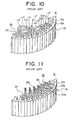
- FIG. 10 is a perspective view of a primary part of the conventional stator, viewed from the rear side thereof.
- FIG. 11 is a perspective view of the primary part of the conventional stator, viewed from the front side thereof.
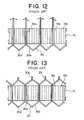
- FIGS. 12 and 13 are schematic diagrams illustrating a method of winding the conventional stator coils.
- the stator core 15 is formed like a cylinder and has a plurality of teeth 15a (each having a rectangular section) provided along the circumference thereof at an equiangular pitch in such a manner as to inwardly radially project therefrom.
- a slot 15b for accommodating the coil therein is formed between each pair of adjacent teeth 15a.
- Each of the slots 15b extends in parallel with the axial direction and is opened to the inner circumference of the stator core 15.
- the rotor 7 has 12 magnetic pole pieces, and the stator 8 has 36 slots 15b.
- the number of slots per magnetic pole and per phase is 1.
- Each of the stator coils 16 is constituted by (nearly U-shaped) coil pieces 30 as follows.
- Each of the coil pieces 30 has a pair of leg portions 30a connected by a nearly V-shaped connecting portion 30b.
- the leg portions 30a of each of the coil pieces 30 are inserted into two slots 15b, whose slot numbers are different from each other by three, from the rear side of the stator core 15.
- open-end portions 30c extending toward the front side of the stator core 15 are joined together.
- the stator coils 16 are constructed.
- a coil conductor is constructed by connecting and integrating the coil pieces 30.
- Two coil pieces 30 are inserted into each set of the two slots 15b, whose slot numbers are by 3, from the rear side of the stator core 15, as shown in FIG. 12.
- 4 leg portions 30a are accommodated in each of the slots 15b in such a manner as to be radially arranged in a line, as illustrated in FIG. 9.
- the leg portions 30a of the outer-circumference-side coil piece 30 are inserted into a first place, which is closest to the outer circumference, in one of the slots 15b, whose slot numbers differ from each other by 3, and into the second place closest to the outer circumference, in the other slot 15b.
- leg portions 30a of the inner-circumference-side coil piece 30 are inserted into a third place, which is the third closest place to the outer circumference, in one of the slots 15b, whose slot numbers differ from each other by 3, and into a fourth place, which is the fourth closest place to the outer circumference, in the other slot 15b.
- the open-end portions 30a of each of the coil pieces 30 are bent in such a way as to outwardly open (that is, bent outwardly circumferentially). Furthermore, the open-end portion 30c of the coil piece 30 extending to the front side of the stator core 15 from the second outmost place in the corresponding slot 15b is made to overlap with the open-end portion 30c of another coil piece 30 extending to the front side from the first outmost place in another slot 15b, whose slot number differs from that of the former slot 15b by 3, as illustrated in FIGS. 11 and 13.
- this inner-circumference-side coil is joined with an end portion u4 of the other outer-circumference-side coil.
- a four-turn coil corresponding to one phase is obtained.
- the end portion u1 of the former inner-circumference-side coil is connected to the rectifier 12 as a lead wire.
- the end portion u4' of the latter outer-circumference-side coil is connected to a neutral point in a star three-phase connection among this coil and coils respectively corresponding to other two phases.
- each of the u1'-u2 connection portion, the u2'-u3 connection portion and the u3'-u4 connection portion is not constituted by the connecting portion of the coil piece. Instead, these connection portions are formed outside the coil end portions, as crossover connection portions, as illustrated in FIG. 10. Incidentally, although three crossover connection portions are shown in FIG. 10, the stator actually has coils respectively corresponding to three phases. Thus, the stator has nine crossover connection portions.
- the coil pieces 30 are inserted into the slots 15b from the rear side thereof. Moreover, the open-end portions 30c extending to the front side thereof are connected to each other as described above. Thus, the coil pieces 30 have almost the same shape. This results in increase in productivity of stators and easiness in being shaped after the fabrication thereof. Consequently, this reduces time and effort to perform the step of shaping the coil after the coil pieces are inserted into slots and connected to each other.
- connection portions for connecting the open-end portions 30c of the coil pieces 30 are concentrated at the front side of the stator. This enhances the workability in a process of connecting the open-end portions.
- each of the nearly U-shaped coil pieces 30 is folded back nearly at the center of the corresponding connecting portion 30b.
- Both leg portions 30a of each of the coil pieces 30 are deviated from the folded-back portion in such a way as to suitably be accommodated in the slots 15b.
- each of the coil pieces 30 is inserted at a predetermined angle with respect to the circumference of the stator 8.
- the longitudinal direction of each of the coil pieces 30 is a radial direction of the stator 8 at the folded-back portion thereof.
- one of the leg portions 30a is placed along a radius extending from the center of the stator core 15, while the other leg portion 30a is placed along a different radius of the stator core 15.
- FIG. 14 is a rear elevation illustrating the coil connection of an improved stator applied to a conventional vehicular AC generator.
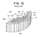
- FIG. 15 is a perspective view of a primary part of the improved stator applied to the conventional vehicular AC generator viewed from the rear side thereof.
- two coil pieces 30 are inserted from the rear side of the stator core 15 into each of the slots 15b whose slot numbers differ by three from each other.
- four leg portions 30a are axially arranged in a line and accommodated in each of the slots 15b.
- two leg portions 30a of each of the coil pieces 30 are sequentially inserted into the second outermost place in a slot 15b and the third outermost place in another slot 15b, which is the third slot from the former slot 15b in the clockwise circumferential direction in FIG. 14.
- two leg portions 30a of another coil piece 30 are serially inserted into the first outermost place in a slot 15b and into the fourth outermost place in another slot 15b, which is the third slot from the former slot 15b in the clockwise circumferential direction in FIG. 14, in such a manner as to stride over the connecting portion 30c of the coil piece 30 having leg portions precedingly inserted into the second outermost place in a slot 15b and into the third outermost place in another slot 15b, which is the third slot from the former slot 15b.
- the rear-side coil end portion is configured by stacking the connecting portions 30c of the coil pieces 30 as two layers as shown in FIG. 15.
- each coil piece 30 having leg portions respectively inserted into the second outermost place in a slot 15b and into the third outermost place in another slot 15b the open-end portions thereof extending from the slot 15b toward the front side of the stator core 15 are bent in such a way as to outwardly open, that is, bent outwardly.
- the open-end portions thereof extending from the slot 15b toward the front side of the stator core 15 are bent inwardly.
- the open-end portion 30c of the coil piece 30 extending to the front side of the stator core 15 from the second outmost place in the corresponding slot 15b, as indicated by dotted lines in FIG. 14, is made to overlap with the open-end portion 30c of another coil piece 30 extending to the front side from the first outmost place in another slot 15b, whose slot number differs from that of the former slot 15b by 3 in the counterclockwise circumferentially, as illustrated in FIG. 14. Then, these open-end portions 30c are crimped with a clip. Subsequently, these open-end portions 30c are soldered to each other.
- the open-end portion 30c of the coil piece 30 extending to the front side of the stator core 15 from the third outmost place in the corresponding slot 15b, as indicated by dotted lines in FIG. 14, is made to overlap with the open-end portion 30c of another coil piece 30 extending to the front side from the fourth outmost place in another slot 15b, whose slot number differs from that of the former slot 15b by 3 in the clockwise circumferentially, as illustrated in FIG. 14.
- these open-end portions 30c are crimped with a clip. Subsequently, these open-end portions 30c are soldered to each other.
- the connecting portion 30b (thus, the rear-side coil end portions) is cut off from the coil piece 30 having leg portions respectively inserted into the second outermost place in one slot of the one set of the slots 15b, whose slot number differs from each other by three, and into the third outermost place in another slot 15b. Furthermore, the connecting portion 30b (thus, the rear-side coil end portions) is cut off from the coil piece 30 having leg portions respectively inserted into the first outermost place in one slot of the one set of the slots 15b, whose slot number differs from each other by three, and into the fourth outermost place in another slot 15b.
- the end portion u1 acts as a lead wire, and the end portion u4' is connected to a neutral point.
- stator has coils respectively corresponding to three phases.
- stator has three crossover connection portions.
- each of constituent phase coils of the stator coils 16 of the stator 8 is constituted by a four-turn coil.
- the crossover connection portion of each turn is provided at the side opposite to the part connecting the open-end portions 30c. Moreover, the crossover connection portion of each turn protrudes outwardly axially from the coil end portion.
- the height of the coil end portion at the side of the connecting portion 30b of each of the coil pieces 30 (namely, the dimension of a part projecting from the end surface of the stator core 15) can be reduced, the crossover connection portion of each turn outwardly axially protrudes from the aligned coil end portions, so that the wind resistance at the discharge side of each of the fans increases. Consequently, the total air quantity of the fans decreases, and the cooling ability of the generator is degraded.
- the axial height of the rear-side coil end portion is large, the ability to cool rear-side internal fittings, such as the rectifier 12 and the regulator 18, is adversely affected.
- the conventional vehicular AC generator has a problem in that higher-order discomfort interference noises are generated between the coil end portion and the fan 5 or the coil end portion and the shoulder of each of the claw-like magnetic pole piece 23 of the pole core 21 and that thus, wind noises are loud.
- the conventional vehicular AC generator has another problem in that it is necessary for connecting 4-turn coils to cut, bend and draw the coil pieces 30 and that thus, the workability thereof is extremely deteriorated.
- the conventional vehicular AC generator has another problem in that, owing to vibrations thereof, a break is liable to occur in the crossover connection portions and that thus, the risk of power-generation failure is increased.
- stator coil 16A of the improved stator 8A the number of the crossover connection portion between four-turn coil constituting each of constituent phase coils is reduced to one.
- the work load of cutting, bending and drawing the coil pieces 30 so as to form the crossover connection portion is alleviated. Consequently, the workability in winding the stator coil is considerably enhanced.
- apex portions 30d of the connecting portions 30b of the coil pieces 30 are axially stacked as two layers and are circumferentially arranged, so that the height of the coil end portion is large and the wind resistance at the discharge side of each of the fans increases. Consequently, the total air quantity of the fans decreases, and the cooling ability of the generator is degraded.
- the apex portions 30d of the connecting portions 30b are axially stacked as two layers, so that inner connecting portions 30b are covered by outer connecting portions 30b.
- an object of the present invention is to provide a vehicular AC generator, which enhances the workability in winding the stator coil and prevents deterioration in ability to cool devices and increase in wind noises due to the projection of crossover connection portions from coil end portions by devising a coil winding structure so as to reduce and omit the crossover connection portions of turns of each constituent phase coil and to expose apex portions of connecting portions of coil pieces.
- a vehicular AC generator comprising the features of claim 1.
- the number of the crossover connection portions of the first and second coils corresponding to the phases is reduced to 1.
- the number of axial projections provided on the aligned coil end portions is decreased.
- the wind resistance at the discharge side of the fan is reduced. Consequently, the cooling ability of the generator is enhanced.
- the discomfort higher-order interference noises generated between the coil end portion and the rotor or the coil end portion and the fan are reduced.
- the wind noises are decreased.
- the number of crossover connection portions formed by connecting the end portions of the second coil piece is reduced. Consequently, an occurrence of power generation failure due to a break in the crossover connection portions, which is caused by vibrations, is prevented.
- the second coil pieces are constructed by which U-shaped coil pieces respectively are inserted from the axial side into the two sets of two of the separated slots so that the U-shaped coil pieces are respectively positioned at a first outermost place in one slot of each of the two sets and at a fourth outermost place in the other slot of each of the two sets, and each of the U-shaped coil pieces is cut off at each connecting portion thereof after inserted into the slots.
- the work of cutting, bending and drawing the second coil piece is reduced.
- a process of assembling the stator coil is simplified. The assemblability of the stator is enhanced.
- each of the first coil pieces is formed by being folded at a connecting portion thereof, and wherein a direction, in which the first coil pieces respectively inserted into a first outermost place in one slot of each set of two of the separated slots and into a second outermost place in the other slot is folded at the connecting portion thereof, is the same with a direction, in which the first coil pieces respectively inserted into a third outermost place in one slot of each set of two of the separated slots and into a fourth outermost place in the other slot is folded at the connecting portion thereof, and is opposite to a direction, in which the first coil pieces respectively inserted into a third outermost place in one slot of each set of two of the separated slots and into a second outermost place in the other slot is folded at the connecting portion thereof.
- the interference between the crossover connection portion and the first coil is suppressed. Consequently, the size of the coil end portions is reduced.
- the crossover connection portion is formed in such a manner as to have a height which is less than that of a coil end portion constructed by a connecting portion of each of the first coil pieces.
- a height which is less than that of a coil end portion constructed by a connecting portion of each of the first coil pieces.
- a vehicular AC generator which comprises the features of claim 5.
- the connecting portion of the first coil pieces which are positioned at the first outermost place in one slot of one set of two of the separated slots and at the third outermost place in the other slot of the one set, is substituted for the crossover connection portions of the phase coils. Consequently, there is no axial projection in the aligned coil end portions. Thus, the wind resistance at the discharge side of the fan is decreased. The cooling ability of the generator is improved. Moreover, the higher-order discomfort interference noises generated between the coil end portion and the rotor or the coil end portion and the fan are reduced. Furthermore, the work of connecting the crossover connection portion, namely, the work of cutting, bending and drawing the coil pieces is omitted. Thus, the assemblability of the stator is enhanced.
- the connecting portions of the first coil pieces constituting the coil end portion are arranged in the circumferential direction by setting heights of apex portion of the connecting portion at an equal value, enabling cooling ability of the AC generator to be enhanced.
- the second coil pieces are constructed by which a nearly U-shaped coil piece is inserted from the axial side into the one set of two of the separated slots so that the U-shaped coil piece is respectively positioned at a second outermost place in one slot of the one set and at a fourth outermost place in the other slot of the one set, and the U-shaped coil piece is cut off at a connecting portion thereof after inserted into the slots.
- the process of producing the stator coil is simplified. Consequently, the workability is enhanced.
- the connecting portion of the first coil pieces which are positioned at the first outermost place in one slot of one set of two of the separated slots and at the fourth outermost place in the other slot of the one set, is substituted for the crossover connection portions of the phase coils. Consequently, the aligned coil end portion has no axial projections formed on the crossover connection portion. Therefore, the wind resistance at the discharge side of the fan is reduced. Moreover, the cooling ability of the generator is enhanced. Furthermore, the higher-order discomfort interference noises generated between the coil end portion and the rotor or the coil end portion and the fan are reduced. The wind noises are decreased. Additionally, the work of connecting the crossover connection portion, that is, the work of cutting, bending and drawing the coil pieces is omitted.
- the assemblability of the stator is enhanced. Furthermore, the crossover connection portions formed by connecting end portions of coil pieces are omitted. Consequently, an occurrence of power generation failure owing to a break in the crossover connection portion, which is caused y vibrations, is prevented.
- the second coil pieces are constructed by which a U-shaped coil piece is inserted from the axial side into the one set of two of the separated slots so that the U-shaped coil piece is respectively positioned at a second outermost place in one slot of the one set and at a third outermost place in the other slot of the one set, and the U-shaped coil piece is cut off at a connecting portion thereof after inserted into the slots.
- two leg portions of one coil piece are respectively inserted from an axial side into a set of slots, whose slot numbers differ from each other by a predetermined number, and then the inserted coil piece is cut off at the connecting portion thereof. Consequently, the process of producing the stator coil is simplified. The workability is enhanced.
- a coil end portion constituted by a connecting portion of the first coil piece is placed at a rear side.
- the height of the rear-side coil end portion is reduced. Consequently, the internal devices, such as the rectifier and the regulator, to be cooled are effectively cooled.
- an axial height of a rear-side coil end portion in a axial direction is lower than that of a front-side coil end portion and an axial lap amount between the front-side coil end portion and the fan is larger than that between the rear-side coil end portion and the fan.
- gaps between the apex portion of the rear-side coil end portion and the internal fittings and between the apex portion of the rear-side coil end portion and an apex-facing surface of the bracket facing to the apex of the rear-side coil end portion are uniformly formed in a circumferential direction.
- the apex portions of the connecting portions of the first coil pieces are exposed in an axial direction.
- the open-end portions of the first and second coil pieces are of the same uniform height by chucking the stator core and holding the connecting portions thereof in the jointing process before the open-end portions are jointed. Consequently, the open-end portions are jointed in a stable condition and the workability in jointing between the open-end portions is enhanced.
- the fan is fixed to a rear-side axial end of the rotor.
- the rear-side cooling air path in which-the cooling air flows is formed, enabling temperature increases in the internal fittings to be suppressed.
- the fans are fixed to both axial end of the rotor.
- the rear-side and front-side cooling air path in which the cooling air flows are formed, enabling cooling ability in the AC generator to be enhanced.
- front-side exhaust wind volume is larger than rear-side exhaust wind volume.
- front-side exhaust wind volume having a low wind resistance increases compared with the rear-side exhaust wind volume having a high wind resistance, preventing wind noise from being deteriorated.
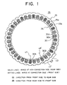
- FIG. 1 is a rear elevation illustrating the coil connection of a stator applied to a vehicular AC generator, which is the first embodiment of the present invention.
- FIG. 2 is a perspective view of a primary part of the stator applied to the vehicular AC generator, which is the first embodiment of the present invention, viewed from the rear side thereof.
- a stator 35 of the first embodiment consists of a stator core 15 and a stator coil 36.
- the stator coil 36 is constituted by (nearly U-shaped) coil pieces 30 as follows.
- Each of the coil pieces 30 has a pair of leg portions 30a connected by a nearly V-shaped connecting portion 30b.
- the leg portions 30a of each of the coil pieces 30 are inserted into two slots 15b, whose slot numbers are different from each other by three, from the rear side of the stator core 15.
- open-end portions 30c extending toward the front side of the stator core 15 are joined together.
- the number of crossover connection portions of each phase coil is reduced to 1 by devising a coil wiring method.
- stator 35 Next, the structure of the stator 35 will be described hereinbelow with reference to FIGS. 1 and 2.
- Two coil pieces 30 are inserted from the rear side of the stator core 15 into each set of the slots 15b whose slot numbers differ by three from each other. At that time, four leg portions 30a are radially arranged in a line and accommodated in each of the slots 15b. Further, two leg portions 30a of each of the outer-circumference-side coil piece 30 are respectively inserted into the first outermost place in a slot 15b and the second outermost place in another slot 15b, which is the third slot from the former slot 15b in the clockwise circumferential direction in FIG. 1.
- a rear-side coil end portion 36r is configured by arranging in the circumferential direction the apex portions (return portion) of the connecting portions 30b of the coil pieces 30 aligned in two rows in the radial direction as shown in FIG. 2.
- the slot inserting positions, into which leg portions of a coil piece 30 are inserted, in each of adjacent two sets of the slots 15b, whose slot numbers differ from each other by three, are set to differ from those in other sets of such two slots 15b.
- the leg portions of one coil piece 30 are respectively inserted into the first outermost place in one of these two slots 15b from the outer-circumference and into the fourth outermost place in the other slot 15b, whose slot number differs from that of the former slot 15b by three in the clockwise circumference direction in FIG. 1.
- leg portions of another coil piece 30 are respectively inserted into the third outermost place in one of these two slots 15b and into the second outermost place in the other slot 15b, whose slot number differs from that of the former slot 15b by three in the clockwise circumferential direction in FIG. 1.
- the former coil piece 30 corresponds to a second coil piece, which has leg portions respectively inserted into the first outermost place in one of these two slots 15b from the outer-circumference and into the fourth outermost place in the other slot 15b, whose slot number differs from that of the former slot 15b by three in the clockwise circumference direction in FIG. 1.
- the other coil piece 30 corresponds to a first coil piece.
- each of the coil pieces 30 is folded back at the apex portion 30d of the connecting portion 30b so that a pair of leg portions 30a thereof are deviated from each other in the radial direction in FIG. 1.
- each of coil pieces 30A and 30B which has leg portions respectively inserted into the third outermost place in one of two slots 15b and into the second outermost place in the other slot 15b whose slot number differs from that of the former slot 15b by three in the clockwise circumferential direction, is adapted so that the direction, in which the leg portions thereof are folded back at the apex portion 30d of the connecting portion 30b, is opposite to such a direction in the case of other coil pieces 30 so as to suppress the interference from those coil pieces 30.
- the rear-side coil end portion 36r is configured by arranging in the circumferential direction the apex portions (return portion) of the connecting portions 30b of the coil pieces 30 aligned in two rows in the radial direction as shown in FIGS. 1 and 2.
- the open-end sides extending toward the front side are outwardly bent.
- the open-end portion 30c of the coil piece 30, which extends to the front side from the second outermost place of a slot 15b is made to overlap with the open-end portion 30c of another coil piece 30 extending to the front side from the first outmost place in another slot 15b, whose slot number differs from that of the former slot 15b by three. Then, these open-end portions 30c are crimped with a clip. Subsequently, these open-end portions 30c are soldered to each other.
- two-turn outer-circumference-side coil (namely, a first coil), which consists of twelve connected outer-circumference-side coil pieces 30, are produced.
- the open-end portion 30c of the coil piece 30 extending to the front side of the stator core 15 from the fourth outmost place in the corresponding slot 15b is made to overlap with the open-end portion 30c of another coil piece 30 extending to the front side from the third outmost place in another slot 15b, whose slot number differs from that of the former slot 15b by 3, as indicated by dotted lines in FIG. 1.
- these open-end portions 30c are crimped with a clip.
- these open-end portions 30c are soldered to each other. Consequently, two-turn inner-circumference-side coil (namely, a second coil), which consists of twelve connected inner-circumference-side coil pieces 30, are produced.
- the connecting portions 30b are cut off from each coil piece 30 having leg portions respectively inserted into the first outermost place in one slot of two sets of the slots 15b and into the fourth outermost place in another slot 15b, whose slot number differs by three from that of the former slot 15b in the clockwise circumferential direction in FIG. 1.
- end portions u2' and u3 of each coil piece 30, which are cut off and extend from the first outermost place in the slot 15b, are made to overlap with each other and joined together.
- a four-turn coil corresponding to a phase is produced.
- end portions u1 and u4' of each of the cut coil pieces 30 extend from the fourth outermost place in the slot 15b to the rear side of the stator core 15, as shown in FIG. 2.
- coils corresponding to other two phases are similarly produced. Furthermore, the end portion u1 of the cut coil piece 30 is connected to the rectifier 12 as a lead wire. Moreover, the end portion u4' of another coil piece 30 is connected to a neutral point in a star three-phase connection among this coil and coils respectively corresponding to other two phases.
- each of the u1'-u2 connection portion and the u3'-u4 connection portion, which are necessary for the conventional stator coil 16, are replaced with the coil pieces 30A and 30B, each of which has leg portions respectively inserted into the third outermost place in one of the slots 15b and into the second outermost place in another slot 15b, whose slot number differs from that of the former slot 15b by three in the circumferential direction.
- the stator actually has coils respectively corresponding to three phases, the stator has three crossover connection portions.
- the coil pieces 30 are inserted into the slots 15b from the rear side thereof, similarly as in the conventional generator. Moreover, the open-end portions 30c extending to the front side thereof are connected to each other as described above. Thus, stator coils 36 are produced. Consequently, the coil pieces 30 have almost the same shape. This results in increase in productivity of stators and easiness in being shaped after the fabrication thereof. Consequently, this reduces time and effort to perform the step of shaping the coil after the coil pieces are inserted into slots and connected to each other. Furthermore, connection portions for connecting the open-end portions 30c of the coil pieces 30 are concentrated at the front side of the stator. This enhances the workability in a process of connecting the open-end portions.
- the number of the crossover connection portions between 4-turn coils constituting constituent phase coil of the stator coil 36 is reduced to 1.
- the work load of cutting, bending and drawing the coil pieces 30 so as to form the crossover connection portion is alleviated. Consequently, the workability thereof is considerably enhanced.
- the risk of a break in the crossover connection portion due to vibrations of the vehicular AC generator is reduced. Consequently, an occurrence of power-generation failure owing to the break in the crossover connection portion is prevented.
- the crossover connection portion u2'-u3 is configured by overlapping and connecting the end portions u2' and u3 of each coil piece 30, which extend toward the rear side thereof from the first outermost place in the slots 15b after cut off at the connecting portions.
- this crossover connection portion is placed at the outer-diameter-side of the coil end portion and positioned between the coil end portion and the bracket. Therefore, neither the height of the coil end portion nor the wind resistance at the discharge side of the fan 5 is increased by forming the crossover connection portion. Consequently, the total air quantity of the fans is restrained from decreasing, so that the temperature of each part of the generator is prevented from rising.
- the connecting portion 30b of the coil piece 30, which serves to reduce the height of the coil end portion, is placed at the rear side of the stator.
- the wind resistance decreases at the discharge side of the rear-side fan. Consequently, the rear-side internal fittings, such as the rectifier 12 and the regulator 18, are efficiently cooled.
- the rear-side coil end portions have no axial projections due to the crossover connection portion. This prevents the generation of higher-order discomfort interference noises between the coil end portion and the fan 5 or the coil end portion and the shoulder of the claw-like magnetic pole 23 of the pole core 21. Consequently, wind noises are reduced.
- the crossover connection portion is placed at the outside-diameter side of the coil end portion, so that the coils are prevented from being damaged and that high quality output and performance are achieved.
- the apex portions 30d of the connecting portions 30b of coil pieces 30 constituting the stator coil 36 are aligned as two rows in the radial direction and are arranged in the circumferential direction, so that the height of the coil end portion is small and the wind resistance at the discharge side of each of the fans decreases. Consequently, the total air quantity of the fans increases, and the cooling ability of the generator is enhanced.
- the apex portions 30d of the connecting portions 30b are exposed in the axial direction, so that the open-end portions 30c thereof are of the same uniform height by chucking the stator core 15 and holding a plane jig to the apex portions 30d of the connecting portions 30b of all coil pieces 30 in the jointing process of the open-end portions of the coil pieces 30 before the open-end portions 30c are jointed.
- the open-end portions 30c are jointed, the height of the open-end portions 30c are maintained uniformly, so that the open-end portions 30c are jointed in such a stable condition and the workability in jointing between the open-end portions 30c is enhanced.
- the height of the coil end portion constituted by the connecting portions 30b of the coil pieces 30 in the axial direction is smaller than that of the coil end portion constituted by jointing the open-end portions 30c thereof.
- the coil end portion constituted by the connecting portions 30b of the coil pieces 30 is disposed at the rear side.
- the height of the rear-side coin end portion 36r is lower than that of a front-side coil end portion 36f so that the wind resistance at the rear side decreases, that is, the air quantity at the rear side increases. Consequently, the rear-side internal fittings, such as the rectifier 12 and the regulator 18, are efficiently cooled.
- a front-side cooling air path in which the outer air is sucked in from the intake openings 1a cools the front-side coil end portion of the stator coil 36 and then is discharged to the outside from the exhaust opening 1b and a rear-side cooling air path in which the outer air is sucked in from the intake openings 2a, respectively, cooling the rectifier 12 and the regulator 18, cools the rear-side coil end portion of the stator coil 36 and then is discharged to the outside from the exhaust opening 2b are formed, realizing the good cooling ability.
- the rear-side cooling air path has a high wind resistance as the rectifier 12 and the regulator 18 are disposed in the rear-side cooling air path.
- the front-side cooling air path has a low wind resistance as there is no internal fittings in the front-side cooling air path.
- the wind resistance of the front-side cooling air path is not particularly increased even if the axial lap amount between the front-side coil end portion and the fan 5 is increased, because the front-side cooling air path has a low wind resistance due to no internal fittings. Further, since there is no internal fittings in the front-side cooling air path, it is possible to suppress temperature increases in the cooling air flowing through the front-side cooling air path and the area of the front-side coil end portion on which the cooling air hits is increased. Thus, the large area of the front-side coil end portion is exposed to the cooling air, enabling temperature increases in the stator coil to be efficiently suppressed.
- the cooling air paths constituted by the apex portion of the coil end portion and the opposite plane of the rear bracket 2, and by the apex portion of the coil end portion and the rectifier 12 and the regulator 18 are formed so as to have a uniform gap in the circumferential direction, respectively.
- the front-side exhaust wind volume is larger than the rear-side exhaust wind volume. Accordingly, the front-side exhaust air which is possible to cool the coil end portion efficiently increases in wind volume compared with the rear-side exhaust air, enabling. Consequently, the stator coil is efficiently cooled, enabling temperature increases in the rectifier 12 and the regulator 18 to be suppressed. Furthermore, the front-side exhaust wind volume having a low wind resistance increases compared with the rear-side exhaust wind volume having a high wind resistance, preventing wind noise from being deteriorated.
- the leg portions of the nearly U-shaped coil pieces are inserted into the first outermost place in one of two slots 15b, whose slot numbers differ from each other by three, and into the fourth outermost place in the other slot 15b, whose slot number differs from that of the former one 15b in the clockwise circumferential direction in FIG. 1, and that the connecting portions 30b (namely, the rear-side coil end portions) of the coil pieces 30 are, thereafter, cut off.
- the present invention is not limited to this generator.
- the generator according to be present invention may be adapted so that rod-like coil pieces are inserted into the first outermost place in one of two slots 15b, whose slot numbers differ from each other by three, and into the fourth outermost place in the other slot 15b, whose slot number differs from that of the former one 15b in the clockwise circumferential direction in FIG. 1 in such a way as to axially extend to both sides thereof. This obviates the necessity of cutting off the connecting portions 30b of the coil pieces 30.
- the crossover connection portion u2'-u3 is configured by overlapping and connecting the end portions u2' and u3 of each coil piece 30, which extend toward the rear side thereof from the first outermost place in the slots 15b after cut off at the connecting portions.
- the crossover connection portion u2'-u3 may be configured by overlapping and connecting the end portions u1 and u4' of each coil piece 30, which extend toward the rear side thereof from the fourth outermost place in the slots 15b after cut off at the connecting portions.
- each coil piece 30 which extend toward the rear side thereof from the first outermost place in the slots 15b after cut off at the connecting portions, are connected to the rectifier 12 as a lead wire and to a neutral point in a star three-phase connection among this coil and coils respectively corresponding to other two phases, respectively.
- the apex portions 30d of the connecting portions of the coil pieces 30 constituting the stator coil 36 are radially aligned in two rows and are arranged in the circumferential direction.
- the apex portions 30d may be arranged in a single row in the circumferential direction, enabling the same effects to be achieved.
- the fans 5 are fixed to both axial ends of the rotor 7.
- the fans 5 are not necessarily disposed at both axial ends of the rotor 7.
- the fan 5 may be fixed to the only rear-side axial end of the rotor 7. In this case, though cooling efficiency in the front-side coil end portion is reduced, a flow of the cooling air is formed by the rotation of the fan 5 at the rear side, cooling the rectifier 12 and the regulator 18 and then cooling the rear-side coil end portion, enabling temperature increases in the stator coil to be suppressed. Further, the fan 5 is disposed at only the rear side of the rotor 7, enabling costs to be lowered.
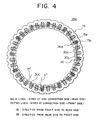
- FIG. 4 is a rear elevation illustrating the coil connection of a stator applied to a vehicular AC generator, which is the second embodiment of the present invention.
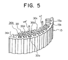
- FIG. 5 is a perspective view of a primary part of the stator applied to the vehicular AC generator, which is the second embodiment of the present invention, viewed from the rear side thereof.
- two coil pieces 30 are inserted from the rear side of the stator core 15 into each of the slots 15b whose slot numbers differ by three from each other.
- four leg portions 30a are radially arranged in a line and accommodated in each of the slots 15b.
- two leg portions 30a of each of the coil pieces 30 are sequentially inserted into the second outermost place in a slot 15b and the third outermost place in another slot 15b, which is the third slot from the former slot 15b in the clockwise circumferential direction in FIG. 4.
- two leg portions 30a of another coil piece 30 are serially inserted into the first outermost place in a slot 15b and into the fourth outermost place in another slot I5b, which is the third slot from the former slot 15b in the clockwise circumferential direction in FIG. 4, in such a manner as to get the apex portion (return portion) of the connecting portion 30b thereof between the apex portions of the connecting portions 30b of the coil pieces 30 having leg portions precedingly inserted into the second outermost place in a slot 15b and into the third outermost place in another slot 15b, which is the third slot from the former slot 15b.
- the rear-side coil end portion is configured by arranging the apex portions of the connecting portions 30b of the coil pieces 30 in a single row in the circumferential direction as shown in FIG. 5.
- the slot inserting positions, into which leg portions of a coil piece 30 are inserted, in one set of the slots 15b, whose slot numbers differ from each other by three, are set to differ from those in other sets of such two slots 15b.
- the leg portions of one coil piece 30 are respectively inserted into the first outermost place in one of the two slots 15b from the outer-circumference and into the third outermost place in the other slot 15b, whose slot number differs from that of the former slot 15b by three in the clockwise circumference direction in FIG. 4.
- leg portions of the other coil piece 30 are respectively inserted into the second outermost place in one of the two slots 15b and into the fourth outermost place in the other slot 15b, whose slot number differs from that of the former slot 15b by three in the clockwise circumferential direction in FIG. 4.
- the coil piece 30 corresponds to a second coil piece, which has leg portions respectively inserted into the second outermost place in one of these two slots 15b from the outer-circumference and into the fourth outermost place in the other slot 15b, whose slot number differs from that of the former slot 15b by three in the clockwise circumference direction in FIG. 4.
- the other coil piece 30 corresponds to a first coil piece.
- each coil piece 30 having leg portions respectively inserted into the second outermost place in a slot 15b and into the third outermost place in another slot 15b the open-end portions thereof extending from the slot 15b toward the front side of the stator core 15 are bent in such a way as to outwardly open, that is, bent outwardly.
- the open-end portions thereof extending from the slot 15b toward the front side of the stator core 15 are bent inwardly.
- each coil piece 30 having leg portions respectively inserted into the first outermost place in a slot 15b and into the third outermost place in another slot 15b, the open-end portion thereof extending from the first outermost place in the slot 15b toward the front side of the stator core 15 is bent inwardly, and the open-end portion thereof extending from the third outermost place in the slot 15b toward the front side of the stator core 15 is bent outwardly.
- each coil piece 30 having leg portions respectively inserted into the second outermost place in a slot 15b and into the fourth outermost place in another slot 15b, the open-end portion thereof extending from the second outermost place in the slot 15b toward the front side of the stator core 15 is bent outwardly, and the open-end portion thereof extending from the fourth outermost place in the slot 15b toward the front side of the stator core 15 is bent inwardly.
- the open-end portion 30c of the coil piece 30 extending to the front side of the stator core 15 from the second outmost place in the corresponding slot 15b is made to overlap with the open-end portion 30c of another coil piece 30 extending to the front side from the first outmost place in another slot 15b, whose slot number differs from that of the former slot 15b by 3 in the counterclockwise circumferentially, as illustrated in FIG. 4. Then, these open-end portions 30c are crimped with a clip. Subsequently, these open-end portions 30c are soldered to each other.
- the open-end portion 30c of the coil piece 30 extending to the front side of the stator core 15 from the third outmost place in the corresponding slot 15b, as indicated by dotted lines in FIG. 4, is made to overlap with the open-end portion 30c of another coil piece 30 extending to the front side from the fourth outmost place in another slot 15b, whose slot number differs from that of the former slot 15b by 3 in the clockwise circumferentially, as illustrated in FIG. 4.
- these open-end portions 30c are crimped with a clip. Subsequently, these open-end portions 30c are soldered to each other.
- a first two-turn coil and a second two-turn coil each consisting of twelve connected coil pieces 30 are connected at the connecting portion 30b of the coil piece 30C having leg portions respectively inserted into the first outermost place in one slot 15b and into the third outermost place in another slot 15b, whose slot number differs from that of the former slot 15b.
- a four-turn coil constituted by connecting 24 coil pieces 30 is obtained.
- the connecting portion 30b (thus, the rear-side coil end portions) is cut off from the coil piece 30 having leg portions respectively inserted into the second outermost place in one slot of the one set of the slots 15b, whose slot number differs from each other by three, and into the fourth outermost place in another slot 15b.
- the end portion u1 acts as a lead wire, and the end portion u4' is connected to a neutral point.
- the u2'-u3 connection portion is necessary for the stator coil 36 of the aforementioned first embodiment.
- the connecting portion 30b of the coil piece 30C corresponds to the u2'-u3 connecting portion.
- the coil piece 30C has leg portions respectively inserted into the first outermost place in one of the slots 15b and into the third outermost place in the other slot 15b, whose slot number differs from that of the former slot 15b by three in the circumferential direction.
- the second embodiment obviates the crossover connection portion.
- the connecting portion 30b of the stator coil 30C is substituted for the crossover connection portion between the four-turn coils constituting each constituent phase coil of the stator coil 36A. Consequently, the second embodiment obviates the crossover connection portion.
- the second embodiment obviates the work of cutting, bending and drawing the coil pieces so as to form the crossover connection portion. Consequently, the workability thereof is considerably enhanced.
- the crossover connection portion is eliminated, the height of the coil end portion is reduced.
- the wind resistance at the discharge side of the fan 5 is decreased. Consequently, the total air quantity of the fans is restrained from decreasing, so that the temperature of each part of the generator is prevented from rising.
- the rear-side internal fittings, such as the rectifier 12 and the regulator 18, are efficiently cooled.
- the coil end portions have no axial projections due to the crossover connection portion. This prevents the generation of higher-order discomfort interference noises between the coil end portion and the fan 5 or the coil end portion and the shoulder of the claw-like magnetic pole 23 of the pole core 21. Consequently, wind noises are reduced.
- crossover connection portion is placed between the coil end portion and the bracket, similarly as in the aforementioned first embodiment, an insulation failure between the crossover connection portion and the bracket may occur. However, such an insulation failure does not occur in the second embodiment.
- the second embodiment eliminates the risk of damage to the coils due to the mixed condition of the crossover connection portion and the coil of the coil end portion. Consequently, the second embodiment achieves high quality output and high performance.
- the apex portions of the connecting portions 30b of the coil pieces 30 constituting the stator coil 36A are arranged in a single row in the circumferential direction, the height of the coil end portion is reduced and the wind resistance at the discharge side of the fan is reduced. As a result, the total air quantity of the fans is increased, enabling cooling ability in the AC generator to be enhanced.
- the open-end portions 30c of the coil pieces 30 are soldered to each other in such a stable condition that the stator core 15 is chucked and the connecting portions 30b of the coil pieces 30 are held, enabling the workability in soldering between the open-end portions 30c to be enhanced.
- the leg portions of the nearly U-shaped coil pieces are inserted into the second outermost place in one of two slots 15b, whose slot numbers differ from each other by three, and into the fourth outermost place in the other slot 15b, whose slot number differs from that of the former one 15b in the clockwise circumferential direction in FIG. 4, and that the connecting portion 30b (namely, the rear-side coil end portion) of the coil pieces 30 is, thereafter, cut off.
- the present invention is not limited to this generator.
- the generator according to be present invention may be adapted so that rod-like coil pieces are inserted into the second outermost place in one of two slots 15b, whose slot numbers differ from each other by three, and into the fourth outermost place in the other slot 15b, whose slot number differs from that of the former one 15b in the clockwise circumferential direction in FIG. 4 in such a way as to axially extend to both sides thereof. This obviates the necessity of cutting off the connecting portion 30b of the coil piece 30.
- the end portions u1 and u4' of the coil piece 30, which respectively extend toward the rear side thereof from the second and fourth outermost places in the slots 15b after cut off therefrom, serve as a lead wire connected to the rectifier 12 and a wire connected to a neutral point among this coil and coils respectively corresponding to other two phases.
- the end portions u1 and u4' may be respectively used as a wire connected to the neutral point and a lead wire connected to the rectifier 12.
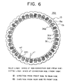
- FIG. 6 is a rear elevation illustrating the coil connection of a stator applied to a vehicular AC generator, which is the third embodiment of the present invention.
- FIG. 7 is a perspective view of a primary part of the stator applied to the vehicular AC generator, which is the third embodiment of the present invention, viewed from the rear side thereof.
- two coil pieces 30 are inserted from the rear side of the stator core 15 into each set of the slots 15b whose slot numbers differ by three from each other.
- four leg portions 30a are radially arranged in a line and accommodated in each of the slots 15b.
- two leg portions 30a of each of the coil piece 30 are sequentially inserted into the first outermost place in a slot 15b and the third outermost place in another slot 15b, which is the third slot from the former slot 15b in the clockwise circumferential direction in FIG. 6.
- two leg portions 30a of another coil piece 30 are serially inserted into the second outermost place in a slot 15b and into the fourth outermost place in another slot 15b, which is the third slot from the former slot 15b in the clockwise circumferential direction in FIG. 6.
- the apex portions of the connecting portions 30b of the coil pieces 30 are aligned in two rows in the radial direction and are arranged in the circumferential direction as shown in FIG. 7.
- the slot inserting positions, into which leg portions of a coil piece 30 are inserted, in one set of the slots 15b, whose slot numbers differ from each other by three, are changed to those in the other sets of such two slots 15b.
- the leg portions of one coil piece 30 (30D) are respectively inserted into the first outermost place in one of these two slots 15b from the outer-circumference and into the fourth outermost place in the other slot 15b, whose slot number differs from that of the former slot 15b by three in the clockwise circumference direction in FIG. 6.
- leg portions of the other coil piece 30 are respectively inserted into the second outermost place in one of the two slots 15b and into the third outermost place in the other slot 15b, whose slot number differs from that of the former slot 15b by three in the clockwise circumferential direction in FIG. 6.
- the coil piece 30 corresponds to a second coil piece, which has leg portions respectively inserted into the second outermost place in one of these two slots 15b from the outer-circumference and into the third outermost place in the other slot 15b, whose slot number differs from that of the former slot 15b by three in the clockwise circumference direction in FIG. 6.
- the other coil piece 30 corresponds to a first coil piece.
- each coil piece 30 having leg portions respectively inserted into the first outermost place in a slot 15b and into the third outermost place in another slot 15b the open-end portions thereof extending from the slot 15b toward the front side of the stator core 15 are bent inwardly. Furthermore, in the case of each coil piece 30 having leg portions respectively inserted into the second outermost place in a slot 15b and into the fourth outermost place in another slot 15b, the open-end portions thereof extending from the slot 15b toward the front side of the stator core 15 are bent in such a way as to outwardly open.
- the open-end portion thereof extending from the first outermost place in the slot 15b toward the front side of the stator core 15 are bent inwardly, and the open-end portion thereof extending from the fourth outermost place in the slot 15b toward the front side of the stator core 15 are bent outwardly.
- the open-end portion thereof extending from the second outermost place in the slot 15b toward the front side of the stator core 15 are bent outwardly, and the open-end portion thereof extending from the third outermost place in the slot 15b toward the front side of the stator core 15 are bent inwardly.
- the open-end portion 30c of the coil piece 30 extending to the front side of the stator core 15 from the first outmost place in the corresponding slot 15b, as indicated by dotted lines in FIG. 6, is made to overlap with the open-end portion 30c of the coil piece 30 extending to the front side from the second outmost place in another slot 15b, whose slot number differs from that of the former slot 15b by three in the counterclockwise circumferentially, as illustrated in FIG. 6. Then, these open-end portions 30c are crimped with a clip. Subsequently, these open-end portions 30c are soldered to each other.
- the open-end portion 30c of the coil piece 30 extending to the front side of the stator core 15 from the third outmost place in the corresponding slot 15b, as indicated by dotted lines in FIG. 6, is made to overlap with the open-end portion 30c of the coil piece 30 extending to the front side from the fourth outmost place in another slot 15b, whose slot number differs from that of the former slot 15b by three in the counterclockwise circumferentially, as illustrated in FIG. 6. Then, these open-end portions 30c are crimped with a clip. Subsequently, these open-end portions 30c are soldered to each other.
- a first two-turn coil and a second two-turn coil consisting of twelve connected coil pieces 30 are connected at the connecting portion 30b of the coil piece 30D having leg portions respectively inserted into the first outermost place in one slot 15b and into the fourth outermost place in another slot 15b, whose slot number differs from that of the former slot 15b.
- a four-turn coil constituted by connecting 24 coil pieces 30 is obtained.
- the connecting portion 30b (thus, the rear-side coil end portion) is cut off from the coil piece 30 having leg portions respectively inserted into the second outermost place in one slot of a set of the slots 15b and into the third outermost place in another slot 15b, whose slot number differs by three from that of the former slot 15b.
- end portions u1 and u4' of the coil piece 30, which are cut off therefrom and respectively extend from the second and third places in the slots 15b to the rear side of the stator core 15, as illustrated in FIG. 6.
- the end portion u1 acts as a lead wire, and the end portion u4' is connected to a neutral point.
- the end portion u1 of the cut coil piece 30 is connected to the rectifier 12 as a lead wire. Moreover, the end portion u4' of this coil piece 30 is connected to a neutral point in a star three-phase connection among this coil and coils respectively corresponding to other two phases. Thus, a stator 35B is obtained.
- the u2'-u3 connection portion is necessary for the stator coil 36 of the aforementioned first embodiment.
- the connecting portion 30b of the coil piece 30D corresponds to the u2'-u3 connection portion.
- the coil piece 30D has leg portions respectively inserted into the first outermost place in one of the slots 15b and into the fourth outermost place in another slot 15b, whose slot number differs from that of the former slot 15b by three in the circumferential direction.
- the third embodiment obviates the crossover connection portion.
- the connecting portion 30b of the stator coil 30D is substituted for the crossover connection portion between the four-turn coils constituting each constituent phase coil of the stator coil 36B. Consequently, the third embodiment obviates the crossover connection portion.
- the third embodiment obviates the work of cutting, bending and drawing the coil pieces so as to form the crossover connection portion. Consequently, the workability thereof is considerably enhanced.
- the crossover connection portion is eliminated, the height of the coil end portion is reduced.
- the wind resistance at the discharge side of the fan 5 is decreased. Consequently, the total air quantity of the fans is restrained from decreasing, so that the temperature of each part of the generator is prevented from rising.
- the rear-side internal fittings are efficiently cooled.
- the coil end portions have no axial projections due to the crossover connection portion. This prevents the generation of higher-order discomfort interference noises between the coil end portion and the fan 5 or the coil end portion and the shoulder of the claw-like magnetic pole 23 of the pole core 21. Consequently, wind noises are reduced.
- crossover connection portion is placed between the coil end portion and the bracket, similarly as in the aforementioned first embodiment, an insulation failure between the crossover connection portion and the bracket may occur. However, such an insulation failure does not occur in the third embodiment.
- the third embodiment eliminates the risk of damage to the coils due to the mixed condition of the crossover connection portion and the coil of the coil end portion. Consequently, the third embodiment achieves high quality output and high performance.
- the coil pieces 30 of each phase coil is configured by having nearly the same shape. Thus, there is little overlap between the coil pieces. Consequently, the height of the coil end portion is reduced to a small value. Moreover, the damage to the coil is reduced.
- the apex portions of the connecting portions 30b of the coil pieces 30 constituting the stator coil 36B are arranged in a single row in the circumferential direction, the height of the coil end portion is reduced and the wind resistance at the discharge side of the fan is reduced. As a result, the total air quantity of the fans is increased, enabling cooling ability in the AC generator to be enhanced.
- the open-end portions 30c of the coil pieces 30 are soldered to each other in such a stable condition that the stator core 15 is chucked and the connecting portions 30b of the coil pieces 30 are held, enabling the workability in soldering between the open-end portions 30c to be enhanced.
- the leg portions of the nearly U-shaped coil pieces 30 are inserted into the second outermost place in one of two slots 15b, whose slot numbers differ from each other by three, and into the third outermost place in the other slot 15b, whose slot number differs from that of the former one 15b in the clockwise circumferential direction in FIG. 6, and that the connecting portions 30b (namely, the rear-side coil end portions) of the coil pieces 30 are, thereafter, cut off.
- the present invention is not limited to this generator.
- the generator according to be present invention may be adapted so that the rod-like coil pieces are inserted into the second outermost place in one of two slots 15b, whose slot numbers differ from each other by three, and into the third outermost place in the other slot 15b, whose slot number differs from that of the former one 15b in the clockwise circumferential direction in FIG. 6 in such a way as to axially extend to both sides thereof. This obviates the necessity of cutting off the connecting portions 30b of the coil pieces 30.
- the end portions u1 and u4' may be respectively used as a wire connected to the neutral point and a lead wire connected to the rectifier 12.
- the three phase AC generators having the slots, of which the number corresponding to each phase and to each pole is 1 have been described.
- the present invention can be applied to a three phase AC generator having slots of which the number corresponding to each phase and to each pole is 2 or more, and to other multi-phase AC generators, such as a six phase AC generator.
- the number of slots corresponding to each phase and to each pole and the number of phases increase, the number of crossover connections increases, so that the advantageous effects of the present invention are brought into the fore.
- each of the aforementioned embodiments uses a round coil having a circular section as the coil piece 30.
- a flat coil having a rectangular section may be used as the coil piece 30.
- the open-end portions 30c of the coil pieces 30 are made to overlap with each other, and then crimped by using the a clip, and subsequently, soldered to each other.
- the coil pieces are connected to each other by soldering.
- means for connecting the open-end portions 30c of the coil pieces 30 is not limited to soldering.
- the open-end portions 30c may be connected to each other by welding.
- the after-treatment of the coil end portion is described nowhere.
- the coil end portion may be impregnated with any insulating resin.
- insulating ability in the connected portions is enhanced.
- the crossover connection portion is integrally fixed to the coil end portion, the risk of a brake in the crossover connection portion due to vibration of the vehicular AC generator is reduced.
Landscapes
- Engineering & Computer Science (AREA)
- Power Engineering (AREA)
- Windings For Motors And Generators (AREA)
- Synchronous Machinery (AREA)
Claims (10)
- Fahrzeug-Wechselstromgenerator mit:einer Welle (6), die in zwei Gehäusehälften (1, 2) drehbar gelagert ist;einem Rotor (7), der an der Welle angebracht und in den zwei Gehäusehälften angeordnet ist;einem Ständer (35), der an einer Außenumfangsseite des Rotors angeordnet und an den zwei Gehäusehälften befestigt ist;internen Anschlussstücken (12, 18), die an der Rückseite des Rotors angeordnet sind; undeinem Lüfter, der von einer Rotation der Welle angetrieben wird und eine Strömung von Kühlluft, die entlang einer Achse der Welle fließt, schafft,bei dem der Ständereinen Ständerkern (15), in dem eine Mehrzahl von Schlitzen (15a), deren Nuten sich in eine axiale Richtung erstrecken, in Umfangsrichtung in einer gleichwinkligen Teilung derart vorgesehen sind, dass sie sich zu einer inneren Umfangsseite öffnen; undeine Ständerspule (36) aufweist, die durch das Einsetzen von Spulendrähten in die Schlitze, die voneinander durch ein vorgegebenes Intervall von 3n Schlitzen, wobei n ganzzahlig ist, getrennt sind, ausgestaltet ist, wobei die Spulendrähte zu viert in einer Linie in einer radialen Richtung angeordnet sind,in dem die Spulendrähte Spulenteile (30) aufweisen, und zwarU-förmige erste Spulenteile, die von einer axialen Seite in zwei benachbarte Paare von Schlitzen eingesetzt sind, wobei die Schlitze eines jeden Paares 3n Schlitze getrennt voneinander liegen, sodass die ersten Spulenteile jeweils auf einem drittäußersten Platz in einem Schlitz von jedem der zwei nebeneinander liegenden Paare und auf einem zweitäußersten Platz in dem anderen Schlitz von jedem der zwei nebeneinander liegenden Paare positioniert sind, und dass die verbleibenden ersten Spulenteile von einer axialen Seite in die verbleibenden Paare von Schlitzen jeweils 3n Schlitze entfernt, eingesetzt sind, sodass eines der verbleibenden ersten Spulenteile jeweils auf einem ersten äußersten Platz in einem Schlitz von jedem der verbleibenden Paare und auf einem zweitäußersten Platz in dem anderen Schlitz von jedem der verbleibenden Paare positioniert ist und dass ein weiteres verbleibendes erstes Spulenteil jeweils an einem drittäußersten Platz in dem einen Schlitz von jedem der verbleibenden Paare und in einem viertäußersten Platz in dem anderen Schlitz von jedem der verbleibenden Paare positioniert ist; undzweite Spulenteile, die in die zwei nebeneinander liegenden Paare der Schlitze jeweils 3n Schlitze entfernt eingesetzt sind, so dass die zweiten Spulenteile jeweils auf einem ersten äußersten Platz in einem Schlitz von jedem der zwei Paare und auf einem viertäußersten Platz des anderen Schlitzes von jedem der zwei Paare positioniert sind, und dass Endabschnitte des zweiten Spulenteils sich von jedem Schlitz der zwei Paare in beide axiale Richtungen erstrecken;bei dem eine erste Spule mit zwei Windungen durch Verbinden eines Endabschnitts von jedem der ersten Spulenteile, welcher sich von dem zweitäußersten Platz in jedem der Schlitze zu einer axial gegenüberliegenden Seite erstreckt und welcher in Umfangsrichtung nach außen gebogen ist, mit einem entsprechenden Endabschnitt der ersten und zweiten Spulenteile, die sich von dem äußersten Platz des Schlitzes, dessen Schlitznummer sich hiervon durch das vorgegebene Schlitzintervall unterscheidet, zu der axial gegenüberliegenden Seite erstrecken und welche in Umfangsrichtung nach außen gebogen sind, gebildet wird;eine zweite Spule mit zwei Windungen durch Verbinden eines Endabschnitts von jedem der ersten und zweiten Spulenteile, welche sich von dem viertäußersten Platz in den Schlitzen zu der axial gegenüberliegenden Seite erstrecken und in Umfangsrichtung nach außen gebogen sind, mit einem entsprechenden Endabschnitt des ersten Spulenteils, welcher sich von dem drittäußersten Platz in dem Schlitz, dessen Schlitznummer sich hiervon durch das vorgegebene Schlitzintervall unterscheidet, zu der axial gegenüberliegenden Seite erstreckt und in Umfangsrichtung nach außen gebogen ist, gebildet ist; undein Überkreuzverbindungsabschnitt zwischen den ersten und zweiten Spulen durch Verbinden von einem der ersten und zweiten Sets von Endabschnitten der zweiten Spulenteile gebildet ist, wobei sich das erste Set von Endabschnitten (u2', u3) des zweiten Spulenteils von dem ersten äußersten Platz in den Schlitz von jedem der zwei nebeneinander liegenden Paare zu der axialen Seite erstreckt, und das zweite Set von Endabschnitten (u1, u4') des zweiten Spulenteils sich vom viertäußersten Platz in den anderen Schlitz von jedem der zwei nebeneinander liegenden Paare zu der axialen Seite erstreckt, wobei das andere Set von Endabschnitten als Verbindungsdraht und als ein Draht, der mit einem neutralen Punkt, der zwischen den Phasenspulen gebildet wird, genutzt wird.
- Fahrzeug-Wechselstromgenerator nach Anspruch 1, in dem die zweiten Spulenteile (30) dadurch dass diese U-förmigen Spulenteile jeweils von der axialen Seite in die zwei nebeneinander liegenden Paare von Schlitzen eingesetzt sind, so dass die U-förmigen Spulenteile jeweils auf einem ersten äußersten Platz in einem Schlitz von jedem der zwei Paare von Schlitzen und auf einem viertäußersten Platz in dem anderen Schlitz von jedem der zwei Paare von Schlitzen, positioniert sind, und jedes der U-förmigen Spulenteile an jedem Verbindungsabschnitt (30b) nachdem es in die Schlitze eingesetzt ist abgeschnitten wird, ausgebildet sind.
- Fahrzeug-Wechselstromgenerator nach Anspruch 1 oder 2, bei dem jedes der ersten Spulenteile (30, 30A, 30B) durch Falten an einem Verbindungsabschnitt (30b) ausgestaltet ist, und bei dem eine Richtung, in die das erste Spulenteil (30), das jeweils in einen ersten äußersten Platz in einem Schlitz von jedem nebeneinander liegenden Paar von Schlitzen und in einen zweitäußersten Platz in dem anderen Schlitz eingesetzt ist, an dem Verbindungsabschnitt gefaltet ist, die Gleiche ist wie eine Richtung, in die das erste Spulenteil (30), das jeweils in einen drittäußersten Platz in einen Schlitz von jedem Paar von Schlitzen und in einen viertäußersten Platz in dem anderen Schlitz eingesetzt ist, an dem Verbindungsabschnitt gefaltet ist, und entgegengesetzt zu einer Richtung ist, in welcher das erste Spulenteil (30A, 30B), das jeweils in einen drittäußersten Platz in einen Schlitz von jedem der Schlitzpaare und in einen zweitäußersten Platz in den anderen Schlitz eingesetzt ist, an dem Verbindungsabschnitt desselben gefaltet ist.
- Fahrzeug-Wechselstromgenerator nach einem der Ansprüche 1 bis 3, in dem der Überkreuzverbindungsabschnitt so ausgeformt ist, dass er eine Höhe hat, die geringer ist als die von einem Spulenendabschnitt, das durch einen Verbindungsabschnitt von jedem der ersten Spulenteile ausgebildet ist.
- Fahrzeug-Wechselstromgenerator mit:einer Welle (6), die in zwei Gehäusehälften (1, 2) drehbar gelagert ist;einem Rotor (7), der an der Welle angebracht und in den zwei Gehäusehälften angeordnet ist;einem Ständer (35A), der an einer Außenumfangsseite des Rotors angeordnet und an den zwei Gehäusehälften befestigt ist;internen Anschlussstücken (12, 18), die an der Rückseite des Rotors angeordnet sind; undeinem Lüfter, der von einer Rotation der Welle angetrieben wird und eine Strömung von Kühlluft, die entlang einer Achse der Welle fließt, schafft,bei dem der Ständereinen Ständerkern (15), in dem eine Mehrzahl von Schlitzen (15a), deren Nuten sich in eine axiale Richtung erstrecken, in Umfangsrichtung in einer gleichwinkligen Teilung derart vorgesehen sind, dass sie sich zu einer inneren Umfangsseite öffnen; undeine Ständerspule (36A) aufweist, die durch das Einsetzen von Spulendrähten in die Schlitze, die voneinander durch ein vorgegebenes Intervall von 3n Schlitzen, wobei n ganzzahlig ist, getrennt sind, ausgestaltet ist, wobei die Spulendrähte zu viert in einer Linie in einer radialen Richtung angeordnet sind,und in dem jeder der Spulendrähteeines von U-förmigen ersten Spulenteilen (30, 30C), die von einer axialen Seite in das eine Paar der getrennten Schlitze so eingesetzt sind, dass das erste Spulenteil (30C) jeweils auf dem ersten äußersten Platz in einem Schlitz des einen Paares und auf dem drittäußersten Platz in dem anderen Schlitz des einen Paares positioniert ist, und verbleibende erste Spulenteile (30) von einer axialen Seite in die verbleibenden Paare der getrennten Schlitze jeweils eingesetzt sind, so dass eines der verbleibenden ersten Spulenteile jeweils auf dem ersten äußersten Platz in einem Schlitz von jedem der verbleibenden Paare und auf einem viertäußersten Platz in dem anderen Schlitz von jedem der verbleibenden Paare positioniert ist, und dass ein weiteres von den verbleibenden ersten Spulenteilen jeweils auf einem zweitäußersten Platz in dem Schlitz von jedem der verbleibenden Paare und auf dem drittäußersten Platz in dem anderen Schlitz von jedem der verbleibenden Paare positioniert ist; undzweite Spulenteile (30) aufweist, welche die Spulendrähte bilden, und in das Paar von Schlitzen so eingesetzt sind dass die zweiten Spulenteile jeweils auf dem zweitäußersten Platz in dem Schlitz des einen Paares und auf einem viertäußersten Platz des anderen Schlitzes des einen Paares positioniert sind und dass die Endabschnitte des zweiten Spulenteils sich von jedem Schlitz des einen Paares in beide axiale Richtungen erstrecken,bei dem eines der verbleibenden ersten Spulenteile (30), die jeweils von der axialen Seite in den ersten äußersten Platz in einen Schlitz von jedem der verbleibenden Paare und auf den viertäußersten Platz in den anderen Schlitz von jedem der verbleibenden Paare eingesetzt sind, jeweils in jeder Lücke, die zwischen einem weiteren der verbleibenden ersten Spulenteile (30) geformt wird, die jeweils von der axialen Seite auf den zweitäußersten Platz in einen Schlitz von jedem der verbleibenden Paare und auf den drittäußersten Platz in den anderen Schlitz von jedem der verbleibenden Paare, auf dem Verbindungsabschnitt (30b) durch Einstellen von Höhen eines Scheitelabschnitts des Verbindungsabschnitts auf einen gleichen Wert angeordnet ist,bei dem eine Spule mit vier Windungen durch Verbinden eines Endabschnitts von jedem der ersten und zweiten Spulenteile, die sich von dem zweitäußersten Platz in jedem der Schlitze zu einer axial gegenüberliegenden Seite erstrecken und in Umfangsrichtung nach außen gebogen sind, mit einem entsprechenden Endabschnitt der ersten Spulenteile, die sich von dem ersten äußersten Platz des Schlitzes, dessen Schlitznummer sich voneinander durch das vorgegebene Schlitzintervall unterscheidet, zu der axial gegenüberliegenden Seite erstrecken und in Umfangsrichtung nach innen gebogen sind und ein Endabschnitt von jedem der ersten und zweiten Spulenteile, die sich von dem viertäußersten Platz in die Schlitze zu der axial gegenüberliegenden Seite erstrecken und in Umfangsrichtung nach innen gebogen sind, ist mit einem entsprechenden Endabschnitt der ersten Spulenteile, die sich von dem drittäußersten Platz in die Schlitze, deren Schlitznummer sich voneinander durch das vorgegebene Schlitzintervall unterscheiden, zu der axial gegenüberliegenden Seite erstrecken und in Umfangsrichtung nach außen gebogen sind, verbunden, ausgestaltet wird,und bei dem ein Endabschnitt (u1) des zweiten Spulenteils (30), der sich von dem zweitäußersten Platz in dem einen Schlitz des einen Paares zu der axialen Seite erstreckt, und ein Endabschnitt (u4') des zweiten Spulenteils, der sich von dem viertäußersten Platz in dem anderen Schlitz des einen Paares zu der axialen Seite erstreckt, als ein Verbindungsdraht und ein Draht, der mit einem neutralen Punkt, der zwischen den Phasenspulen ausgebildet ist, verbunden ist, genutzt wird.
- Fahrzeug-Wechselstromgenerator nach Anspruch 5, bei dem die zweiten Spulenteile (30) dadurch dass ein U-förmiges Spulenteil von der axialen Seite in das eine Paar von Schlitzen so eingesetzt wird, dass das U-förmige Spulenteil jeweils auf dem zweitäußersten Platz in einem Schlitz des einen Paares und auf einem viertäußersten Platz in dem anderen Schlitz des einen Paares, positioniert ist, und das U-förmige Spulenteil an einem Verbindungsabschnitt (30b) nach dem Einsetzen in die Schlitze abgeschnitten ist, gebildet werden.
- Fahrzeug-Wechselstromgenerator mit:einer Welle (6), die in zwei Gehäusehälften (1, 2) drehbar gelagert ist;einem Rotor (7), der an der Welle angebracht und in den zwei Gehäusehälften angeordnet ist;einem Ständer (35B), der an einer Außenumfangsseite des Rotors angeordnet und an den zwei Gehäusehälften befestigt ist;internen Anschlussstücken (12, 18), die an der Rückseite des Rotors angeordnet sind; undeinem Lüfter, der von einer Rotation der Welle angetrieben wird und eine Strömung von-Kühlluft, die entlang einer Achse der Welle fließt, schafft,bei dem der Ständereinen Ständerkern (15), in dem eine Mehrzahl von Schlitzen, deren Nuten sich in eine axiale Richtung erstrecken, in Umfangsrichtung in einer gleichwinkligen Teilung derart vorgesehen sind, dass sie sich zu einer inneren Umfangsseite öffnen; undeine Ständerspule (36B) aufweist, die durch das fortlaufende Einsetzen von Spulendrähten in die Schlitze, die voneinander durch ein vorgegebenes Intervall von 3n Schlitzen, wobei n ganzzahlig ist, getrennt sind, ausgestaltet ist, wobei die Spulendrähte zu viert in einer Linie in einer radialen Richtung angeordnet sind,und in dem jeder der Spulendrähteeines von U-förmigen ersten Spulenteilen (30, 30D), die von einer axialen Seite in das eine Paar der Schlitze so eingesetzt sind, dass das erste Spulenteil jeweils auf dem ersten äußersten Platz in einem Schlitz des einen Paares und auf dem viertäußersten Platz in dem anderen Schlitz des einen Paares positioniert ist, und verbleibende erste Spulenteile (30) von einer axialen Seite in die verbleibenden Paare der Schlitze jeweils eingesetzt sind, so dass eines der verbleibenden ersten Spulenteile jeweils auf dem ersten äußersten Platz in einem Schlitz von jedem der verbleibenden Paare und auf einem drittäußersten Platz in dem anderen Schlitz von einem der verbleibenden Paare positioniert ist, und dass ein weiteres von den verbleibenden ersten Spulenteilen jeweils auf einem zweitäußersten Platz in dem Schlitz von jedem der verbleibenden Paare und auf dem viertäußersten Platz in dem anderen Schlitz von jedem der verbleibenden Paare positioniert ist; undzweite Spulenteile (30) aufweist, die in das Paar von Schlitzen so eingesetzt ist dass die zweiten Spulenteile jeweils auf dem zweitäußersten Platz in dem Schlitz des einen Paares und auf einem drittäußersten Platz des anderen Schlitzes des einen Paares positioniert sind und dass die Endabschnitte des zweiten Spulenteils sich von jedem Schlitz des einen Paares in beide axiale Richtungen erstrecken,bei dem eine Spule mit vier Windungen durch Verbinden eines Endabschnitts von jedem der ersten und zweiten Spulenteile, die sich von dem zweitäußersten Platz in jedem der Schlitze zu einer axial gegenüberliegenden Seite erstrecken und in Umfangsrichtung nach außen gebogen sind, mit einem entsprechenden Endabschnitt der ersten Spulenteile, die sich von dem ersten äußersten Platz des Schlitzes, dessen Schlitznummer sich voneinander durch das vorgegebene Schlitzintervall unterscheidet zu der axial gegenüberliegenden Seite erstrecken und in Umfangsrichtung nach innen gebogen sind und ein Endabschnitt von jedem der ersten Spulenteile, die sich von dem viertäußersten Platz in die Schlitze zu der axial gegenüberliegenden Seite erstrecken und in Umfangsrichtung nach außen gebogen sind, ist mit einem entsprechenden Endabschnitt der ersten und zweiten Spulenteile, die sich von dem drittäußersten Platz in die Schlitze, deren Schlitznummer sich voneinander durch das vorgegebene Schlitzintervall unterscheiden, zu der axial gegenüberliegenden Seite erstrecken und in Umfangsrichtung nach innen gebogen sind, verbunden, ausgestaltet wird,und bei dem Endabschnitte (u1, u4') des zweiten Spulenteils (30), die sich von dem zweitäußersten Platz in dem einen Schlitz des einen Paares zu der axialen Seite erstrecken, und von dem drittäußersten Platz in dem anderen Schlitz des einen Paares zu der axialen Seite erstrecken, als ein Verbindungsdraht und ein Draht, der mit einem neutralen Punkt, der zwischen den Phasenspulen ausgebildet ist, verbunden sind, genutzt wird.
- Fahrzeug-Wechselstromgenerator nach Anspruch 7, bei dem die zweiten Spulenteile (30) dadurch dass ein U-förmiges Spulenteil von der axialen Seite in das eine Paar von Schlitzen so eingesetzt wird, dass das U-förmige Spulenteil jeweils auf dem zweitäußersten Platz in einem Schlitz des einen Paares und auf einem drittäußersten Platz in dem anderen Schlitz des einen Paares, positioniert ist, und das U-förmige Spulenteil an einem Verbindungsabschnitt (30b) nach dem Einsetzen in die Schlitze abgeschnitten ist, gebildet werden.
- Fahrzeug-Wechselstromgenerator nach einem der Ansprüche 1 bis 8, bei dem ein Spulenendabschnitt, der aus den Verbindungsabschnitten (30b) des ersten Spulenteils gebildet wird, auf der Rückseite angebracht ist.
- Fahrzeug-Wechselstromgenerator nach Anspruch 9, bei dem eine axiale Höhe eines rückseitigen Spulenendabschnitts in einer axialen Richtung geringer als die des vorderseitigen Spulenendabschnitts ist und ein axialer Überlappungsbetrag zwischen dem vorderseitigen Spulenendabschnitt und dem Lüfter größer als der zwischen dem rückseitigen Spulenendabschnitt und dem Lüfter ist.
Applications Claiming Priority (2)
| Application Number | Priority Date | Filing Date | Title |
|---|---|---|---|
| JP34642999 | 1999-12-06 | ||
| JP34642999A JP3419721B2 (ja) | 1999-12-06 | 1999-12-06 | 車両用交流発電機 |
Publications (3)
| Publication Number | Publication Date |
|---|---|
| EP1107425A2 EP1107425A2 (de) | 2001-06-13 |
| EP1107425A3 EP1107425A3 (de) | 2003-07-30 |
| EP1107425B1 true EP1107425B1 (de) | 2006-08-16 |
Family
ID=18383370
Family Applications (1)
| Application Number | Title | Priority Date | Filing Date |
|---|---|---|---|
| EP00110928A Expired - Lifetime EP1107425B1 (de) | 1999-12-06 | 2000-05-25 | Wechselstromgenerator für Fahrzeuge |
Country Status (5)
| Country | Link |
|---|---|
| US (2) | US6285105B1 (de) |
| EP (1) | EP1107425B1 (de) |
| JP (1) | JP3419721B2 (de) |
| KR (1) | KR100353145B1 (de) |
| DE (1) | DE60030073T2 (de) |
Cited By (2)
| Publication number | Priority date | Publication date | Assignee | Title |
|---|---|---|---|---|
| DE102018218731A1 (de) * | 2018-10-31 | 2020-04-30 | Thyssenkrupp Ag | Stator für eine elektrische Maschine, sowie elektrische Maschine |
| EP3729608A1 (de) * | 2017-12-20 | 2020-10-28 | Valeo Equipements Electriques Moteur | Stator für eine elektrische drehmaschine |
Families Citing this family (45)
| Publication number | Priority date | Publication date | Assignee | Title |
|---|---|---|---|---|
| JP3155534B1 (ja) * | 2000-01-20 | 2001-04-09 | 三菱電機株式会社 | 交流発電機の固定子 |
| JP2001286082A (ja) * | 2000-04-03 | 2001-10-12 | Mitsubishi Electric Corp | 交流発電機の固定子 |
| JP3621635B2 (ja) * | 2000-08-10 | 2005-02-16 | 三菱電機株式会社 | 回転電機 |
| EP1235331B1 (de) * | 2000-09-26 | 2011-11-16 | Mitsubishi Denki Kabushiki Kaisha | Wechselstromgenerator für kraftfahrzeuge |
| US6894415B2 (en) * | 2000-11-06 | 2005-05-17 | Denso Corporation | Stator arrangement of rotary electric machine |
| FR2819117B1 (fr) * | 2000-12-21 | 2004-10-29 | Valeo Equip Electr Moteur | Alternateur a elements conducteurs en epingle pour vehicule automobile |
| JP3566665B2 (ja) * | 2001-04-06 | 2004-09-15 | 三菱電機株式会社 | 回転電機の固定子 |
| JP3740421B2 (ja) * | 2002-01-10 | 2006-02-01 | 株式会社日立製作所 | 回転電機と固定子導線の接続方法 |
| US6750581B2 (en) | 2002-01-24 | 2004-06-15 | Visteon Global Technologies, Inc. | Automotive alternator stator assembly with rectangular continuous wire |
| US6930426B2 (en) * | 2003-11-26 | 2005-08-16 | Visteon Global Technologies, Inc. | Alternator stator having a multiple filar construction to improve convective cooling |
| US7170211B2 (en) * | 2002-01-24 | 2007-01-30 | Visteon Global Technologies, Inc. | Stator winding having transitions |
| GB2389717B (en) * | 2002-01-24 | 2004-07-28 | Visteon Global Tech Inc | Automotive alternator stator assembly and winding method |
| US6882077B2 (en) * | 2002-12-19 | 2005-04-19 | Visteon Global Technologies, Inc. | Stator winding having cascaded end loops |
| US7129612B2 (en) * | 2002-01-24 | 2006-10-31 | Visteon Global Technologies, Inc. | Stator assembly with cascaded winding and method of making same |
| US6794785B2 (en) * | 2002-06-26 | 2004-09-21 | Denso Corporation | Alternator for vehicles |
| DE10342755B4 (de) | 2002-09-17 | 2018-06-14 | Denso Corporation | Rotierende Hochspannungselektromaschine |
| US20040119359A1 (en) * | 2002-12-19 | 2004-06-24 | Visteon Global Technologies, Inc. | Automotive alternator stator assembly with odd number of electrical turns |
| US6949857B2 (en) * | 2003-03-14 | 2005-09-27 | Visteon Global Technologies, Inc. | Stator of a rotary electric machine having stacked core teeth |
| JP4252360B2 (ja) * | 2003-05-21 | 2009-04-08 | 三菱電機株式会社 | 回転電機の固定子 |
| US7081697B2 (en) * | 2004-06-16 | 2006-07-25 | Visteon Global Technologies, Inc. | Dynamoelectric machine stator core with mini caps |
| US7386931B2 (en) * | 2004-07-21 | 2008-06-17 | Visteon Global Technologies, Inc. | Method of forming cascaded stator winding |
| US7269888B2 (en) * | 2004-08-10 | 2007-09-18 | Visteon Global Technologies, Inc. | Method of making cascaded multilayer stator winding with interleaved transitions |
| JP2007037280A (ja) * | 2005-07-27 | 2007-02-08 | Mitsubishi Electric Corp | インバータ一体型回転電機 |
| US7622843B2 (en) * | 2006-06-12 | 2009-11-24 | Rerry International, Inc. | Terminals and connections between multi-set segmented hairpin windings |
| JP5180297B2 (ja) * | 2008-05-30 | 2013-04-10 | パナソニック株式会社 | 同期電動機駆動システム |
| US8040007B2 (en) * | 2008-07-28 | 2011-10-18 | Direct Drive Systems, Inc. | Rotor for electric machine having a sleeve with segmented layers |
| JP5131561B2 (ja) * | 2009-03-13 | 2013-01-30 | アイシン・エィ・ダブリュ株式会社 | コイル製造方法、コイル製造装置、及びコイル |
| US8357726B2 (en) * | 2010-01-20 | 2013-01-22 | Vertex L.L.C. | Devulcanization of rubber and other elastomers |
| US8470897B2 (en) | 2010-01-20 | 2013-06-25 | Vertex L.L.C. | Devulcanization of rubber and other elastomers |
| CA2840973C (en) * | 2011-07-07 | 2018-01-30 | Tecnomatic S.P.A. | Stator for an electric machine |
| DE102012108943B4 (de) * | 2011-09-24 | 2026-01-22 | Denso Corporation | Rotierende elektrische Maschine |
| JP5469687B2 (ja) * | 2011-09-24 | 2014-04-16 | 株式会社日本自動車部品総合研究所 | 回転電機 |
| US9467010B2 (en) | 2011-11-17 | 2016-10-11 | Remy Technologies, L.L.C. | Method of winding a stator core with a continuous conductor having a rectangular cross-section and a stator core |
| US8789259B2 (en) | 2011-11-17 | 2014-07-29 | Remy Technologies, L.L.C. | Method of winding a stator core with a continuous conductor having a rectangular cross-section and a stator core |
| US20130127286A1 (en) * | 2011-11-17 | 2013-05-23 | Remy Technologies, L.L.C. | Continuous stator winding having a rectangular cross-section and method |
| US8745847B2 (en) | 2011-11-17 | 2014-06-10 | Remy Technologies, L.L.C. | Method of P-forming a continuous conductor having a rectangular cross section and a stator including a stator winding formed from a P-formed conductor having a rectangular cross-section |
| JP6022896B2 (ja) * | 2012-10-29 | 2016-11-09 | 日立オートモティブシステムズ株式会社 | 回転電機 |
| JP5804095B2 (ja) * | 2013-01-22 | 2015-11-04 | トヨタ自動車株式会社 | ステータ及びステータの製造方法 |
| JP6135535B2 (ja) * | 2014-02-07 | 2017-05-31 | 株式会社デンソー | 回転電機の固定子 |
| EP3285369B1 (de) | 2015-04-15 | 2022-06-15 | Mitsubishi Electric Corporation | Stator und elektromotorische maschine |
| DE102017129134A1 (de) | 2017-12-07 | 2019-06-13 | Aumann AG | Verfahren zum Herstellen einer Anordnung für eine Steckspule einer elektrischen Maschine und Anordnung |
| JP7434716B2 (ja) * | 2019-03-11 | 2024-02-21 | 株式会社デンソー | 電動駆動装置 |
| JP2020150609A (ja) * | 2019-03-11 | 2020-09-17 | 株式会社デンソー | 電動駆動装置 |
| JP6873219B1 (ja) * | 2019-12-13 | 2021-05-19 | 三菱電機株式会社 | 回転電機 |
| EP4087096A4 (de) * | 2019-12-31 | 2023-09-06 | SAIC MOTOR Corporation Limited | Statorwicklungsstruktur und diese enthaltender motor |
Family Cites Families (18)
| Publication number | Priority date | Publication date | Assignee | Title |
|---|---|---|---|---|
| DE2921114A1 (de) * | 1979-05-25 | 1980-12-04 | Bosch Gmbh Robert | Wickelverfahren fuer einen elektrischen generator und danach hergestellter drehstromgenerator |
| DE3008212C2 (de) * | 1980-03-04 | 1985-06-27 | Robert Bosch Gmbh, 7000 Stuttgart | Verfahren zur Herstellung von Statorwicklungen für Dreiphasen-Drehstromgeneratoren |
| JPH03284147A (ja) * | 1990-03-28 | 1991-12-13 | Mitsubishi Electric Corp | 車両用交流発電機 |
| JP2924112B2 (ja) * | 1990-07-18 | 1999-07-26 | 株式会社デンソー | 三相交流回転電機 |
| JP3041884B2 (ja) * | 1990-05-17 | 2000-05-15 | 株式会社デンソー | 車両用交流発電機 |
| JPH0757077B2 (ja) * | 1990-10-17 | 1995-06-14 | 株式会社東芝 | 三相電機子巻線 |
| KR940001176B1 (ko) * | 1990-07-19 | 1994-02-16 | 가부시끼가이샤 도시바 | 3상 전기자 권선 |
| DE9017835U1 (de) | 1990-10-04 | 1992-03-12 | Robert Bosch Gmbh, 7000 Stuttgart | Ständer für elektrische Maschinen |
| US5691590A (en) * | 1992-10-23 | 1997-11-25 | Nippondenso Co., Ltd. | Alternator with magnetic noise reduction mechanism |
| US5343613A (en) * | 1993-01-27 | 1994-09-06 | Sundstrand Corporation | Method of installing thermal protection for an electric motor stator |
| US5714824A (en) * | 1994-06-23 | 1998-02-03 | Hydro-Quebec | Conductor section for a stator frame of a polyphase dynamoelectric machine |
| US6124660A (en) * | 1997-05-26 | 2000-09-26 | Denso Corporation | AC generator for vehicles |
| WO1998054822A1 (fr) * | 1997-05-26 | 1998-12-03 | Denso Corporation | Alternateur pour vehicule |
| JP3303773B2 (ja) * | 1997-05-26 | 2002-07-22 | 株式会社デンソー | 車両用交流発電機の固定子 |
| US6137201A (en) * | 1997-05-26 | 2000-10-24 | Denso Corporation | AC generator for vehicles |
| JP3285534B2 (ja) * | 1998-04-08 | 2002-05-27 | 三菱電機株式会社 | 車両用交流発電機の固定子 |
| JP3155532B1 (ja) | 1999-12-01 | 2001-04-09 | 三菱電機株式会社 | 車両用交流発電機の固定子 |
| JP3347115B2 (ja) * | 1999-12-20 | 2002-11-20 | 三菱電機株式会社 | 交流発電機 |
-
1999
- 1999-12-06 JP JP34642999A patent/JP3419721B2/ja not_active Expired - Fee Related
-
2000
- 2000-05-01 US US09/561,969 patent/US6285105B1/en not_active Expired - Lifetime
- 2000-05-25 DE DE60030073T patent/DE60030073T2/de not_active Expired - Lifetime
- 2000-05-25 EP EP00110928A patent/EP1107425B1/de not_active Expired - Lifetime
- 2000-08-24 KR KR1020000049225A patent/KR100353145B1/ko not_active Expired - Fee Related
-
2001
- 2001-06-13 US US09/879,131 patent/US6507137B2/en not_active Expired - Lifetime
Cited By (2)
| Publication number | Priority date | Publication date | Assignee | Title |
|---|---|---|---|---|
| EP3729608A1 (de) * | 2017-12-20 | 2020-10-28 | Valeo Equipements Electriques Moteur | Stator für eine elektrische drehmaschine |
| DE102018218731A1 (de) * | 2018-10-31 | 2020-04-30 | Thyssenkrupp Ag | Stator für eine elektrische Maschine, sowie elektrische Maschine |
Also Published As
| Publication number | Publication date |
|---|---|
| JP3419721B2 (ja) | 2003-06-23 |
| KR100353145B1 (ko) | 2002-09-18 |
| EP1107425A3 (de) | 2003-07-30 |
| DE60030073D1 (de) | 2006-09-28 |
| JP2001169491A (ja) | 2001-06-22 |
| US6507137B2 (en) | 2003-01-14 |
| DE60030073T2 (de) | 2007-03-08 |
| US20020047450A1 (en) | 2002-04-25 |
| KR20010067104A (ko) | 2001-07-12 |
| EP1107425A2 (de) | 2001-06-13 |
| US6285105B1 (en) | 2001-09-04 |
Similar Documents
| Publication | Publication Date | Title |
|---|---|---|
| EP1107425B1 (de) | Wechselstromgenerator für Fahrzeuge | |
| US6552463B2 (en) | Dynamo-electric machine having winding phase groups of series-connected windings connected in parallel | |
| US6326715B1 (en) | Stator for an automotive alternator | |
| US6268678B1 (en) | Alternator | |
| EP1211781B1 (de) | Wechselstromgenerator für Fahrzeuge | |
| JP3347116B2 (ja) | 交流発電機 | |
| JP3593009B2 (ja) | 回転電機 | |
| US6348750B1 (en) | Alternator | |
| EP1365495A2 (de) | Dynamoelektrische Wechselstrom-Maschine für Kraftfahrzeuge | |
| US6501204B1 (en) | Stator for an alternator | |
| JP3668938B2 (ja) | 回転電機 | |
| US20110109178A1 (en) | Automotive dynamoelectric stator | |
| JP3484412B2 (ja) | 車両用交流発電機およびその固定子の製造方法 | |
| JP2003348780A (ja) | 回転電機の固定子 | |
| US20020093254A1 (en) | Automotive alternator | |
| US6424071B1 (en) | Automotive alternator | |
| JP2002315246A (ja) | 回転電機の固定子 | |
| US6441526B1 (en) | Alternator | |
| CN100365917C (zh) | 交流发电机 | |
| US7342340B2 (en) | Alternator with identical conductor segments | |
| EP1109295A2 (de) | Wickelkopf der Statorwicklung eines Generators | |
| EP1109290B1 (de) | Statorwicklungen eines Wechselstromgenerators |
Legal Events
| Date | Code | Title | Description |
|---|---|---|---|
| PUAI | Public reference made under article 153(3) epc to a published international application that has entered the european phase |
Free format text: ORIGINAL CODE: 0009012 |
|
| AK | Designated contracting states |
Kind code of ref document: A2 Designated state(s): AT BE CH CY DE DK ES FI FR GB GR IE IT LI LU MC NL PT SE |
|
| AX | Request for extension of the european patent |
Free format text: AL;LT;LV;MK;RO;SI |
|
| PUAL | Search report despatched |
Free format text: ORIGINAL CODE: 0009013 |
|
| AK | Designated contracting states |
Designated state(s): AT BE CH CY DE DK ES FI FR GB GR IE IT LI LU MC NL PT SE |
|
| AX | Request for extension of the european patent |
Extension state: AL LT LV MK RO SI |
|
| 17P | Request for examination filed |
Effective date: 20030730 |
|
| 17Q | First examination report despatched |
Effective date: 20040105 |
|
| AKX | Designation fees paid |
Designated state(s): DE FR GB |
|
| GRAP | Despatch of communication of intention to grant a patent |
Free format text: ORIGINAL CODE: EPIDOSNIGR1 |
|
| RAP1 | Party data changed (applicant data changed or rights of an application transferred) |
Owner name: MITSUBISHI DENKI KABUSHIKI KAISHA |
|
| GRAS | Grant fee paid |
Free format text: ORIGINAL CODE: EPIDOSNIGR3 |
|
| GRAA | (expected) grant |
Free format text: ORIGINAL CODE: 0009210 |
|
| AK | Designated contracting states |
Kind code of ref document: B1 Designated state(s): DE FR GB |
|
| REG | Reference to a national code |
Ref country code: GB Ref legal event code: FG4D |
|
| REF | Corresponds to: |
Ref document number: 60030073 Country of ref document: DE Date of ref document: 20060928 Kind code of ref document: P |
|
| REG | Reference to a national code |
Ref country code: GB Ref legal event code: 727 |
|
| ET | Fr: translation filed | ||
| PLBE | No opposition filed within time limit |
Free format text: ORIGINAL CODE: 0009261 |
|
| STAA | Information on the status of an ep patent application or granted ep patent |
Free format text: STATUS: NO OPPOSITION FILED WITHIN TIME LIMIT |
|
| 26N | No opposition filed |
Effective date: 20070518 |
|
| REG | Reference to a national code |
Ref country code: GB Ref legal event code: 727A |
|
| PGFP | Annual fee paid to national office [announced via postgrant information from national office to epo] |
Ref country code: GB Payment date: 20070523 Year of fee payment: 8 |
|
| REG | Reference to a national code |
Ref country code: GB Ref legal event code: 727B |
|
| GBPC | Gb: european patent ceased through non-payment of renewal fee |
Effective date: 20080525 |
|
| PG25 | Lapsed in a contracting state [announced via postgrant information from national office to epo] |
Ref country code: GB Free format text: LAPSE BECAUSE OF NON-PAYMENT OF DUE FEES Effective date: 20080525 |
|
| PGFP | Annual fee paid to national office [announced via postgrant information from national office to epo] |
Ref country code: DE Payment date: 20140521 Year of fee payment: 15 Ref country code: FR Payment date: 20140509 Year of fee payment: 15 |
|
| REG | Reference to a national code |
Ref country code: DE Ref legal event code: R119 Ref document number: 60030073 Country of ref document: DE |
|
| REG | Reference to a national code |
Ref country code: FR Ref legal event code: ST Effective date: 20160129 |
|
| PG25 | Lapsed in a contracting state [announced via postgrant information from national office to epo] |
Ref country code: DE Free format text: LAPSE BECAUSE OF NON-PAYMENT OF DUE FEES Effective date: 20151201 |
|
| PG25 | Lapsed in a contracting state [announced via postgrant information from national office to epo] |
Ref country code: FR Free format text: LAPSE BECAUSE OF NON-PAYMENT OF DUE FEES Effective date: 20150601 |