EP1107564A2 - Guidage automatique de feuilles vers des passages spécifiques à l'aide d'un rouleau cranté - Google Patents
Guidage automatique de feuilles vers des passages spécifiques à l'aide d'un rouleau cranté Download PDFInfo
- Publication number
- EP1107564A2 EP1107564A2 EP00125439A EP00125439A EP1107564A2 EP 1107564 A2 EP1107564 A2 EP 1107564A2 EP 00125439 A EP00125439 A EP 00125439A EP 00125439 A EP00125439 A EP 00125439A EP 1107564 A2 EP1107564 A2 EP 1107564A2
- Authority
- EP
- European Patent Office
- Prior art keywords
- sheet
- roller assembly
- leading edge
- media
- transport roller
- Prior art date
- Legal status (The legal status is an assumption and is not a legal conclusion. Google has not performed a legal analysis and makes no representation as to the accuracy of the status listed.)
- Withdrawn
Links
Images


Classifications
-
- H—ELECTRICITY
- H04—ELECTRIC COMMUNICATION TECHNIQUE
- H04N—PICTORIAL COMMUNICATION, e.g. TELEVISION
- H04N1/00—Scanning, transmission or reproduction of documents or the like, e.g. facsimile transmission; Details thereof
- H04N1/00567—Handling of original or reproduction media, e.g. cutting, separating, stacking
- H04N1/0057—Conveying sheets before or after scanning
- H04N1/00572—Conveying sheets before or after scanning with refeeding for double-sided scanning, e.g. using one scanning head for both sides of a sheet
-
- H—ELECTRICITY
- H04—ELECTRIC COMMUNICATION TECHNIQUE
- H04N—PICTORIAL COMMUNICATION, e.g. TELEVISION
- H04N1/00—Scanning, transmission or reproduction of documents or the like, e.g. facsimile transmission; Details thereof
- H04N1/00567—Handling of original or reproduction media, e.g. cutting, separating, stacking
- H04N1/0057—Conveying sheets before or after scanning
- H04N1/00599—Using specific components
- H04N1/00602—Feed rollers
-
- H—ELECTRICITY
- H04—ELECTRIC COMMUNICATION TECHNIQUE
- H04N—PICTORIAL COMMUNICATION, e.g. TELEVISION
- H04N1/00—Scanning, transmission or reproduction of documents or the like, e.g. facsimile transmission; Details thereof
- H04N1/00567—Handling of original or reproduction media, e.g. cutting, separating, stacking
- H04N1/0057—Conveying sheets before or after scanning
- H04N1/00599—Using specific components
- H04N1/00612—Path switches
Definitions
- the present invention relates to the transport of individual cut sheets of flat flexible media such as paper, vellum, transparencies or the like through a transport path which may have various branches for the delivery of sheets such as printed sheets of media from an input location to a desired location.
- a transport path which may have various branches for the delivery of sheets such as printed sheets of media from an input location to a desired location.
- the invention will be described in the context of a document scanning apparatus having a sheet transport path which extends from a stack of document sheets to be scanned to and through a scanning location to a scanned document location where the scanned sheets are stacked.
- the invention is concerned with the guiding and movement of sheets in a scanning apparatus or printer capable of duplex scanning or printing wherein one side of a media sheet is first scanned or printed and then, if desired, the individual sheets may then be turned over and routed back to the scanning or printing region for scanning or printing the other side of the sheet.
- the teachings of the invention are applicable generally to any office or business machine in which flexible media sheets must be moved to selected paths.
- sheet processing apparatus is therefore intended to broadly include, but not necessarily be limited to, printers, stand alone document copiers, facsimile machines, document scanning machines and combinations of such units.
- the present invention provides a method of processing sheet media in a sheet processing apparatus comprising the steps of:
- the present invention comprises a sheet media processing apparatus including a sheet media input location, a sheet media processing location, a processed sheet media location and sheet guides defining a media transport path extending from said input location through said processing location to said processed sheet location, sheet transport means for moving individual media sheets along said path, said media transport path including a sheet routing space between a sheet input path and first and second sheet output paths, said sheet transport means including a rotatably driven sheet transport roller assembly in said routing space having a peripheral sheet guide surface arranged and configured to engage a leading edge of said sheet and move said leading edge to one or the other of said output paths, and a power drive for rotating said transport roller assembly in opposite directions to move said leading edge of said sheet into a selected output path and toward said output location.
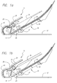
- Figures 1a - 1d are side elevation views sequentially showing the progress of a media sheet through a document scanning apparatus which incorporates the teachings of the present invention.
- Figure 2 is an enlarged side elevation view of a media sheet routing space and a reversible transport roller assembly.
- Figure 3 is a perspective view of the transport roller assembly comprised of a series of spaced coaxially arranged crenellated rollers and drive rollers used in the scanning device of Fig. 1.
- FIGS 1a - 1d are identical schematic side elevation views of a document scanning apparatus 10 showing the passage of an individual document sheet therethrough.
- the apparatus 10 includes a generally flat horizontally extending glass table or platen surface 12 for single sheet scanning and a region 14 at one end thereof through which a moving document to be scanned can be viewed by the scanning components of the device as is conventional.
- An inclined frame 20 supports a document input or feed tray 22 for holding a stack 24 of documents to be fed to the scanning components.
- An inclined surface or guide 26 on the frame 20 and a plurality of stationary media sheet guides 27, 28, 29 on the frame together define a sheet media path extending from the media stack 24 to the scan region 14 and thence past a scanning roller 40 and document output sheet transport roller assembly 50 to a scanned document output location at which a tray 34 is provided for receiving a stack of scanned documents.
- the apparatus for feeding individual sheets from the stack 24 to the scan region 14 includes the inclined media support or feed tray 22, upper and lower media pick rollers 30, 32 and a suitable drive mechanism for moving the rollers 30, 32 in the same forward direction of rotation (e.g., clockwise) for uppermost sheet picking and in the same reverse direction (e.g., counterclockwise) for lowermost sheet picking as described in commonly owned co-pending application Serial No. (HP Docket 10991829-1).
- FIGs 2 and 3 respectively show an end elevation and perspective view of a transport roller assembly 50 comprised of a rotatable shaft 52 having a plurality of rollers 54 affixed thereto at axially spaced locations along the shaft 52.
- Each of the rollers 54 is preferably identical to the other rollers 54 and has a crenellated surface comprised of a cylindrical surface on which generally radially extending projections 56 are formed.
- the projections 56 are preferably equally circumferentially spaced and thus define axially extending spaces or grooves 58 between the projections 56.
- Each of the crenellated rollers 54 is mounted on the shaft 52 for rotation with the shaft 52 and with longitudinal alignment of the projections so that the grooves 58 between the projections also align with each other along the length of the shaft 52.
- the term "crenellated surface” means any suitably roughened surface on a roller or belt wrapped around a roller which defines generally axially extending grooves thereon of width and depth suitable for engaging and moving the leading edge of a sheet of paper or other material engaged in a groove in the direction of rotation of the roller.
- the grooves may be defined for example by axially extending spaced continuous ridges on the roller or belt surface or by axially extending rows of spaced dimple projections on the roller or belt surface or by grooves cut into the cylindrical roller surface or belt.
- roller is intended to include a single elongated roller and the mechanical equivalent of two or more axially spaced rollers on a common shaft or axis.
- two spaced drive rollers 60 are also mounted on the shaft at spaced locations for engaging a sheet of paper or other media inwardly of the marginal edges of the sheet.
- the transport roller assembly may preferably also include a plurality of elongated ribs 70 and circumferential rings 72 to provide support as necessary to the media sheet.
- pinch rollers 62 and 64 respectively positioned above and below the transport roller assembly 50 tangentially engage the drive rollers 60 to provide nips and media sheet delivery paths above and below the transport roller assembly 50.
- the upper pinch rollers 62 are shown in the perspective view of Figure 3 but the lower rollers 64 are seen only in Fig. 3.
- lower pinch rollers 64 are provided in engagement with each of the drive rollers 60.
- the pinch rollers 62, 64 are spaced on diametrically opposite sides of the transport roller assembly 50 although it is not essential to do so.
- the diameter of the drive rollers 60 is preferably slightly less than the diameter of the crenellated rollers 54.
- a suitable power drive is provided for rotating the transport roller assembly including the crenellated surface rollers 54 and drive rollers 60 in either the clockwise or the counterclockwise direction as desired.
- the cylindrical surfaces of the crenellated rollers 54 need not be specially designed for transversely engaging the face of a sheet of media since the drive rollers 60 are primarily used for transporting the sheet of media through nips defined between the drive rollers 60 and the opposed pinch rollers 62, 64. Accordingly, the drive rollers 60 and pinch rollers 62, 64 will be provided with traction surfaces for gripping and transporting media sheets through the nips as is conventional.
- the pinch rollers 62, 64 are spring biased into engagement with the drive rollers 60 and comprise idlers which are only rotatable when the transport roller assembly 50 and drive rollers 60 thereon are rotated.
- the spaced rollers 54, 60 need not be identical since some rollers 54 on a common axis may have a crenellated surface while other rollers 60 may comprise sheet drive rollers having a friction surface, not necessarily crenellated, suitable for engagement with the pinch rollers 62, 64 to define a nip through which media sheets may be driven. It is contemplated that the crenellated rollers may, if desired, have pinch rollers in engagement therewith whereby the crenellated rollers both guide the leading edge of a media sheet toward a nip and then move the sheet through the nips between the crenellated rollers and associated pinch rollers.
- rollers in surface contact define media sheet transport nips therebetween as is well known therefore the term "roller” is intended and specifically defined to include mechanical substitutes having opposed surfaces which define nips such as opposed continuous belts trained around rollers or an opposed roller and belt which together define a nip.
- Figure 1a shows the initial movement of a sheet of paper or other media from the top or bottom of the stack 24 by the opposed pick rollers 30, 32.
- the leading edge of the paper has progressed and has been driven by the document drive roller 40 through the sheet processing location 14, the leading edge of the sheet having reached a location in the sheet transport path defined between the stationary guides 28, 29.
- a timing circuit actuates the power drive to cause rotation of the transport roller assembly 50 in the counterclockwise direction as seen in Figure 1a.
- the document drive roller 40 continues to rotate in the clockwise direction thus again moving the sheet through the sheet processing region 40 until the leading edge of the sheet (previously the trailing edge) comes into contact with the crenellated surfaces of rollers 54 whereby the projections 56 and grooves 58 engage the leading edge of the sheet and lift and thus guide it toward the upper nip defined between the drive rollers 60 and upper pinch rollers 62 so that the document sheet, now having been duplex scanned or printed, may be passed over the transport roller assembly 50 through the upper nip between the drive rollers 60 and upper pinch rollers 62.
- the invention involves the use of a rollers or belts 54 having a crenellated surface to engage the leading edge of a moving media sheet to transport it to one of two output paths such, in the arrangement shown, are above and below the transport roller assembly 50.
- a rollers or belts 54 having a crenellated surface to engage the leading edge of a moving media sheet to transport it to one of two output paths such, in the arrangement shown, are above and below the transport roller assembly 50.
- these teachings need be limited to a horizontally oriented transport roller assembly 50 since the principles of the invention will clearly be applicable to the handling of sheet media moving with its flat surfaces in a non-horizontal path provided that appropriate minor modifications are made.
- separate drive rollers 60 and associated pinch rollers 62, 64 transport the sheet past the transport roller assembly 50 on the selected upper or lower side depending upon the direction of rotation of the transport roller assembly 50.
- pinch rollers 62, 64 can be dispensed with altogether in which instance the pinch rollers 62, 64 would be aligned with and disposed on preferably diametrically opposite sides of the individual crenellated surface rollers 54. Further, it is contemplated that pinch rollers 62, 64 may not be essential in all instances.
- the generally radially extending projections 56 on the crenellated surface rollers can be sized and configured as necessary for slidably engaging the stationary guides 27, 29 to define nips between the projections and stationary guides through which the media sheets may pass depending upon the direction of rotation of the transport roller assembly 50.
- the stationary guides themselves, while primarily being stationary, may have resiliently biased portions tangent to the projections 56 to pinch the moving sheet media therebetween. It will be understood that the resilient biasing results in slight movement of the guides 27, 29 which are essentially otherwise considered stationary guides.
- a single crenellated surface roller 54 having continuous grooves 58 which extend from side to side of the media path can be construed to fulfill such a function.
- the transport roller assembly 50 can be molded or otherwise fabricated of plastics or other light weight materials and that the projections 56 and grooves 58 can be integrally formed in the mold of suitable size to perform their intended function of guiding the leading edge of the paper to the desired nip on opposite sides of the transport roller assembly.
- the details of a suitable drive arrangement for rotating the roller assembly 50 in the desired directions of rotation at the desired time is well within the skill of persons skilled in the art and is therefore not described herein.
Landscapes
- Engineering & Computer Science (AREA)
- Multimedia (AREA)
- Signal Processing (AREA)
- Delivering By Means Of Belts And Rollers (AREA)
- Separation, Sorting, Adjustment, Or Bending Of Sheets To Be Conveyed (AREA)
- Conveyance By Endless Belt Conveyors (AREA)
- Exposure Or Original Feeding In Electrophotography (AREA)
Applications Claiming Priority (2)
| Application Number | Priority Date | Filing Date | Title |
|---|---|---|---|
| US452832 | 1999-12-01 | ||
| US09/452,832 US6241236B1 (en) | 1999-12-01 | 1999-12-01 | Automated sheet delivery to selected paths using reversible crenellated roller |
Publications (2)
| Publication Number | Publication Date |
|---|---|
| EP1107564A2 true EP1107564A2 (fr) | 2001-06-13 |
| EP1107564A3 EP1107564A3 (fr) | 2002-01-16 |
Family
ID=23798123
Family Applications (1)
| Application Number | Title | Priority Date | Filing Date |
|---|---|---|---|
| EP00125439A Withdrawn EP1107564A3 (fr) | 1999-12-01 | 2000-11-20 | Guidage automatique de feuilles vers des passages spécifiques à l'aide d'un rouleau cranté |
Country Status (4)
| Country | Link |
|---|---|
| US (1) | US6241236B1 (fr) |
| EP (1) | EP1107564A3 (fr) |
| JP (1) | JP2001220043A (fr) |
| TW (1) | TW510864B (fr) |
Families Citing this family (3)
| Publication number | Priority date | Publication date | Assignee | Title |
|---|---|---|---|---|
| US6443446B1 (en) * | 2000-07-18 | 2002-09-03 | Eastman Kodak Company | Media transport mechanism for information transfer devices |
| US7766325B2 (en) * | 2004-06-16 | 2010-08-03 | Hewlett-Packard Indigo B.V. | Paper rotation method and apparatus |
| JP2009130722A (ja) * | 2007-11-26 | 2009-06-11 | Oki Data Corp | 画像読取装置及び画像形成装置 |
Family Cites Families (14)
| Publication number | Priority date | Publication date | Assignee | Title |
|---|---|---|---|---|
| US4553828A (en) * | 1983-07-01 | 1985-11-19 | Xerox Corporation | Recirculative document inverter |
| JPS6217741A (ja) | 1985-07-16 | 1987-01-26 | Sharp Corp | 原稿送り装置 |
| US4660963A (en) | 1985-12-30 | 1987-04-28 | Xerox Corporation | Auto duplex reproduction machine |
| US4884097A (en) * | 1987-12-24 | 1989-11-28 | Eastman Kodak Company | Duplex document handler |
| US5016061A (en) | 1988-04-21 | 1991-05-14 | Sharp Kabushiki Kaisha | Recirculating automatic document feeder |
| JP2946112B2 (ja) * | 1990-07-28 | 1999-09-06 | ニスカ株式会社 | 原稿搬送装置 |
| US5181714A (en) * | 1990-11-26 | 1993-01-26 | Sharp Kabushiki Kaisha | Document feeder with adjustable length document reversing transport path |
| US5131649A (en) | 1991-01-03 | 1992-07-21 | Xerox Corporation | Multiple output sheet inverter |
| US5201517A (en) | 1992-06-24 | 1993-04-13 | Xerox Corporation | Orbiting nip plural mode sheet output with faceup or facedown stacking |
| US5215298A (en) | 1992-06-24 | 1993-06-01 | Xerox Corporation | Orbiting nip sheet output with faceup or facedown stacking and integral gate |
| US5430536A (en) | 1993-10-12 | 1995-07-04 | Xerox Corporation | Automatic duplex and simplex document handler for electronic input |
| US5784680A (en) | 1995-10-11 | 1998-07-21 | Ricoh Company, Ltd. | Compact auto-document feeder for an image forming apparatus |
| US5887865A (en) * | 1996-06-10 | 1999-03-30 | Konica Corporation | Document feeder for image-forming apparatus and image-forming apparatus, using the same |
| US5915157A (en) * | 1997-03-26 | 1999-06-22 | Ricoh Company, Ltd. | Sheet transport system and apparatus for an image-forming apparatus with crossing sheet transport paths |
-
1999
- 1999-12-01 US US09/452,832 patent/US6241236B1/en not_active Expired - Fee Related
-
2000
- 2000-08-21 TW TW089116923A patent/TW510864B/zh not_active IP Right Cessation
- 2000-11-20 EP EP00125439A patent/EP1107564A3/fr not_active Withdrawn
- 2000-12-01 JP JP2000366524A patent/JP2001220043A/ja active Pending
Also Published As
| Publication number | Publication date |
|---|---|
| US6241236B1 (en) | 2001-06-05 |
| JP2001220043A (ja) | 2001-08-14 |
| EP1107564A3 (fr) | 2002-01-16 |
| TW510864B (en) | 2002-11-21 |
Similar Documents
| Publication | Publication Date | Title |
|---|---|---|
| CN1325349C (zh) | 在图像阅读设备中的给纸器 | |
| EP1058159B1 (fr) | Duplication recto verso dans un dispositif automatique d'alimentation de documents avec une route plus courte que la longueur du document à copier | |
| JP5372190B2 (ja) | シート分離搬送機構及びそれを備えたシート搬送装置並びに画像形成装置 | |
| JP3249721B2 (ja) | シート材給送装置及び画像形成装置 | |
| US5441249A (en) | Method and device for separating lifts from a stack of sheets | |
| US6241236B1 (en) | Automated sheet delivery to selected paths using reversible crenellated roller | |
| US6305684B1 (en) | Feed rollers with reversing clutch | |
| JPH0676148B2 (ja) | シ−ト材給送装置 | |
| US6293542B1 (en) | Automated sheet delivery to selected paths using active gate and drag clutch | |
| JP2004299871A (ja) | シート排出装置 | |
| US20080265485A1 (en) | Sheet Discharge Roller Assembly For An Automatic Document Feeding Apparatus | |
| US6203005B1 (en) | Feeder apparatus for documents and the like | |
| JPH075071Y2 (ja) | シート搬送装置 | |
| JP2723883B2 (ja) | 給紙装置 | |
| US7540372B2 (en) | Belt driven and roller assisted media transport | |
| JPH0527397Y2 (fr) | ||
| KR20080004357U (ko) | 복사기의 화상형성장치 | |
| JP2831453B2 (ja) | 給紙装置 | |
| JP3623466B2 (ja) | 給紙装置 | |
| JP2592172B2 (ja) | 給紙装置 | |
| JPH10305932A (ja) | シート材給送装置及び画像読取装置並びに画像形成装置 | |
| JPH03124639A (ja) | 給紙装置 | |
| JPH05186077A (ja) | 画像形成装置の給紙機構 | |
| JPH08208065A (ja) | 給紙装置 | |
| JPH06263272A (ja) | シート自動給送装置及び記録装置 |
Legal Events
| Date | Code | Title | Description |
|---|---|---|---|
| PUAI | Public reference made under article 153(3) epc to a published international application that has entered the european phase |
Free format text: ORIGINAL CODE: 0009012 |
|
| AK | Designated contracting states |
Kind code of ref document: A2 Designated state(s): AT BE CH CY DE DK ES FI FR GB GR IE IT LI LU MC NL PT SE TR Kind code of ref document: A2 Designated state(s): DE FR GB |
|
| AX | Request for extension of the european patent |
Free format text: AL;LT;LV;MK;RO;SI |
|
| PUAL | Search report despatched |
Free format text: ORIGINAL CODE: 0009013 |
|
| AK | Designated contracting states |
Kind code of ref document: A3 Designated state(s): AT BE CH CY DE DK ES FI FR GB GR IE IT LI LU MC NL PT SE TR |
|
| AX | Request for extension of the european patent |
Free format text: AL;LT;LV;MK;RO;SI |
|
| 17P | Request for examination filed |
Effective date: 20020716 |
|
| AKX | Designation fees paid |
Free format text: DE FR GB |
|
| GRAP | Despatch of communication of intention to grant a patent |
Free format text: ORIGINAL CODE: EPIDOSNIGR1 |
|
| STAA | Information on the status of an ep patent application or granted ep patent |
Free format text: STATUS: THE APPLICATION IS DEEMED TO BE WITHDRAWN |
|
| 18D | Application deemed to be withdrawn |
Effective date: 20061018 |