EP1107805B1 - Protection des aiguilles lors d'intraveineuses - Google Patents
Protection des aiguilles lors d'intraveineuses Download PDFInfo
- Publication number
- EP1107805B1 EP1107805B1 EP99932558A EP99932558A EP1107805B1 EP 1107805 B1 EP1107805 B1 EP 1107805B1 EP 99932558 A EP99932558 A EP 99932558A EP 99932558 A EP99932558 A EP 99932558A EP 1107805 B1 EP1107805 B1 EP 1107805B1
- Authority
- EP
- European Patent Office
- Prior art keywords
- port
- needle
- guard
- sampling port
- sampling
- Prior art date
- Legal status (The legal status is an assumption and is not a legal conclusion. Google has not performed a legal analysis and makes no representation as to the accuracy of the status listed.)
- Expired - Lifetime
Links
- 238000000034 method Methods 0.000 title claims abstract description 22
- 238000005070 sampling Methods 0.000 claims abstract description 130
- 239000008280 blood Substances 0.000 claims description 42
- 210000004369 blood Anatomy 0.000 claims description 42
- 238000001990 intravenous administration Methods 0.000 claims description 31
- 239000007788 liquid Substances 0.000 claims description 14
- 239000000463 material Substances 0.000 claims description 14
- 238000003780 insertion Methods 0.000 claims description 11
- 230000037431 insertion Effects 0.000 claims description 11
- 239000003463 adsorbent Substances 0.000 claims description 9
- 230000000116 mitigating effect Effects 0.000 claims description 9
- 208000012266 Needlestick injury Diseases 0.000 claims description 7
- 238000000926 separation method Methods 0.000 claims description 5
- 238000011109 contamination Methods 0.000 claims description 4
- 206010053567 Coagulopathies Diseases 0.000 claims description 3
- 230000035602 clotting Effects 0.000 claims description 3
- 239000012530 fluid Substances 0.000 claims description 3
- 229910010293 ceramic material Inorganic materials 0.000 claims description 2
- 230000000717 retained effect Effects 0.000 abstract description 3
- 230000035515 penetration Effects 0.000 description 5
- GWEVSGVZZGPLCZ-UHFFFAOYSA-N Titan oxide Chemical compound O=[Ti]=O GWEVSGVZZGPLCZ-UHFFFAOYSA-N 0.000 description 4
- 238000010586 diagram Methods 0.000 description 4
- 230000000712 assembly Effects 0.000 description 3
- 238000000429 assembly Methods 0.000 description 3
- 238000005530 etching Methods 0.000 description 3
- 239000012528 membrane Substances 0.000 description 3
- 239000002245 particle Substances 0.000 description 3
- 239000002253 acid Substances 0.000 description 2
- 238000000576 coating method Methods 0.000 description 2
- 230000006835 compression Effects 0.000 description 2
- 238000007906 compression Methods 0.000 description 2
- 238000000465 moulding Methods 0.000 description 2
- 238000011282 treatment Methods 0.000 description 2
- 229920003043 Cellulose fiber Polymers 0.000 description 1
- 108010049003 Fibrinogen Proteins 0.000 description 1
- 102000008946 Fibrinogen Human genes 0.000 description 1
- 108010022901 Heparin Lyase Proteins 0.000 description 1
- DGAQECJNVWCQMB-PUAWFVPOSA-M Ilexoside XXIX Chemical compound C[C@@H]1CC[C@@]2(CC[C@@]3(C(=CC[C@H]4[C@]3(CC[C@@H]5[C@@]4(CC[C@@H](C5(C)C)OS(=O)(=O)[O-])C)C)[C@@H]2[C@]1(C)O)C)C(=O)O[C@H]6[C@@H]([C@H]([C@@H]([C@H](O6)CO)O)O)O.[Na+] DGAQECJNVWCQMB-PUAWFVPOSA-M 0.000 description 1
- 239000005909 Kieselgur Substances 0.000 description 1
- FYYHWMGAXLPEAU-UHFFFAOYSA-N Magnesium Chemical compound [Mg] FYYHWMGAXLPEAU-UHFFFAOYSA-N 0.000 description 1
- ZLMJMSJWJFRBEC-UHFFFAOYSA-N Potassium Chemical compound [K] ZLMJMSJWJFRBEC-UHFFFAOYSA-N 0.000 description 1
- VYPSYNLAJGMNEJ-UHFFFAOYSA-N Silicium dioxide Chemical compound O=[Si]=O VYPSYNLAJGMNEJ-UHFFFAOYSA-N 0.000 description 1
- 108090000190 Thrombin Proteins 0.000 description 1
- 150000007513 acids Chemical class 0.000 description 1
- 239000004411 aluminium Substances 0.000 description 1
- XAGFODPZIPBFFR-UHFFFAOYSA-N aluminium Chemical compound [Al] XAGFODPZIPBFFR-UHFFFAOYSA-N 0.000 description 1
- 229910052782 aluminium Inorganic materials 0.000 description 1
- 238000013459 approach Methods 0.000 description 1
- 230000008901 benefit Effects 0.000 description 1
- 230000015572 biosynthetic process Effects 0.000 description 1
- 230000017531 blood circulation Effects 0.000 description 1
- 230000023555 blood coagulation Effects 0.000 description 1
- 210000004204 blood vessel Anatomy 0.000 description 1
- 229920002678 cellulose Polymers 0.000 description 1
- 239000001913 cellulose Substances 0.000 description 1
- 239000004927 clay Substances 0.000 description 1
- 230000008878 coupling Effects 0.000 description 1
- 238000010168 coupling process Methods 0.000 description 1
- 238000005859 coupling reaction Methods 0.000 description 1
- 238000013461 design Methods 0.000 description 1
- 238000000502 dialysis Methods 0.000 description 1
- 230000000694 effects Effects 0.000 description 1
- 229940012952 fibrinogen Drugs 0.000 description 1
- 239000011521 glass Substances 0.000 description 1
- 229910052500 inorganic mineral Inorganic materials 0.000 description 1
- 230000003993 interaction Effects 0.000 description 1
- 239000011777 magnesium Substances 0.000 description 1
- 229910052749 magnesium Inorganic materials 0.000 description 1
- 230000014759 maintenance of location Effects 0.000 description 1
- 239000011707 mineral Substances 0.000 description 1
- 230000004048 modification Effects 0.000 description 1
- 238000012986 modification Methods 0.000 description 1
- 239000002991 molded plastic Substances 0.000 description 1
- 239000003973 paint Substances 0.000 description 1
- 230000037361 pathway Effects 0.000 description 1
- 239000004033 plastic Substances 0.000 description 1
- 239000011591 potassium Substances 0.000 description 1
- 229910052700 potassium Inorganic materials 0.000 description 1
- 239000000843 powder Substances 0.000 description 1
- 102000004196 processed proteins & peptides Human genes 0.000 description 1
- 108090000765 processed proteins & peptides Proteins 0.000 description 1
- 108090000623 proteins and genes Proteins 0.000 description 1
- 102000004169 proteins and genes Human genes 0.000 description 1
- 150000004760 silicates Chemical class 0.000 description 1
- 239000011734 sodium Substances 0.000 description 1
- 229910052708 sodium Inorganic materials 0.000 description 1
- 229920002994 synthetic fiber Polymers 0.000 description 1
- 229960004072 thrombin Drugs 0.000 description 1
- 239000004408 titanium dioxide Substances 0.000 description 1
- 210000003462 vein Anatomy 0.000 description 1
- 239000002699 waste material Substances 0.000 description 1
Images




Classifications
-
- A—HUMAN NECESSITIES
- A61—MEDICAL OR VETERINARY SCIENCE; HYGIENE
- A61B—DIAGNOSIS; SURGERY; IDENTIFICATION
- A61B5/00—Measuring for diagnostic purposes; Identification of persons
- A61B5/15—Devices for taking samples of blood
- A61B5/150992—Blood sampling from a fluid line external to a patient, such as a catheter line, combined with an infusion line; Blood sampling from indwelling needle sets, e.g. sealable ports, luer couplings or valves
-
- A—HUMAN NECESSITIES
- A61—MEDICAL OR VETERINARY SCIENCE; HYGIENE
- A61B—DIAGNOSIS; SURGERY; IDENTIFICATION
- A61B5/00—Measuring for diagnostic purposes; Identification of persons
- A61B5/15—Devices for taking samples of blood
- A61B5/150007—Details
- A61B5/150015—Source of blood
- A61B5/15003—Source of blood for venous or arterial blood
-
- A—HUMAN NECESSITIES
- A61—MEDICAL OR VETERINARY SCIENCE; HYGIENE
- A61B—DIAGNOSIS; SURGERY; IDENTIFICATION
- A61B5/00—Measuring for diagnostic purposes; Identification of persons
- A61B5/15—Devices for taking samples of blood
- A61B5/150007—Details
- A61B5/150351—Caps, stoppers or lids for sealing or closing a blood collection vessel or container, e.g. a test-tube or syringe barrel
-
- A—HUMAN NECESSITIES
- A61—MEDICAL OR VETERINARY SCIENCE; HYGIENE
- A61B—DIAGNOSIS; SURGERY; IDENTIFICATION
- A61B5/00—Measuring for diagnostic purposes; Identification of persons
- A61B5/15—Devices for taking samples of blood
- A61B5/150007—Details
- A61B5/150374—Details of piercing elements or protective means for preventing accidental injuries by such piercing elements
- A61B5/150381—Design of piercing elements
- A61B5/150389—Hollow piercing elements, e.g. canulas, needles, for piercing the skin
-
- A—HUMAN NECESSITIES
- A61—MEDICAL OR VETERINARY SCIENCE; HYGIENE
- A61B—DIAGNOSIS; SURGERY; IDENTIFICATION
- A61B5/00—Measuring for diagnostic purposes; Identification of persons
- A61B5/15—Devices for taking samples of blood
- A61B5/150007—Details
- A61B5/150374—Details of piercing elements or protective means for preventing accidental injuries by such piercing elements
- A61B5/150381—Design of piercing elements
- A61B5/150503—Single-ended needles
-
- A—HUMAN NECESSITIES
- A61—MEDICAL OR VETERINARY SCIENCE; HYGIENE
- A61B—DIAGNOSIS; SURGERY; IDENTIFICATION
- A61B5/00—Measuring for diagnostic purposes; Identification of persons
- A61B5/15—Devices for taking samples of blood
- A61B5/150007—Details
- A61B5/150374—Details of piercing elements or protective means for preventing accidental injuries by such piercing elements
- A61B5/150534—Design of protective means for piercing elements for preventing accidental needle sticks, e.g. shields, caps, protectors, axially extensible sleeves, pivotable protective sleeves
- A61B5/150572—Pierceable protectors, e.g. shields, caps, sleeves or films, e.g. for hygienic purposes
-
- A—HUMAN NECESSITIES
- A61—MEDICAL OR VETERINARY SCIENCE; HYGIENE
- A61B—DIAGNOSIS; SURGERY; IDENTIFICATION
- A61B5/00—Measuring for diagnostic purposes; Identification of persons
- A61B5/15—Devices for taking samples of blood
- A61B5/150007—Details
- A61B5/150374—Details of piercing elements or protective means for preventing accidental injuries by such piercing elements
- A61B5/150534—Design of protective means for piercing elements for preventing accidental needle sticks, e.g. shields, caps, protectors, axially extensible sleeves, pivotable protective sleeves
- A61B5/150633—Protective sleeves which are axially extensible, e.g. sleeves connected to, or integrated in, the piercing or driving device; pivotable protective sleeves
- A61B5/150641—Protective sleeves which are axially extensible, e.g. sleeves connected to, or integrated in, the piercing or driving device; pivotable protective sleeves comprising means to impede repositioning of protection sleeve from covering to uncovering position
-
- A—HUMAN NECESSITIES
- A61—MEDICAL OR VETERINARY SCIENCE; HYGIENE
- A61B—DIAGNOSIS; SURGERY; IDENTIFICATION
- A61B5/00—Measuring for diagnostic purposes; Identification of persons
- A61B5/15—Devices for taking samples of blood
- A61B5/153—Devices specially adapted for taking samples of venous or arterial blood, e.g. with syringes
- A61B5/154—Devices using pre-evacuated means
- A61B5/1545—Devices using pre-evacuated means comprising means for indicating vein or arterial entry
-
- A—HUMAN NECESSITIES
- A61—MEDICAL OR VETERINARY SCIENCE; HYGIENE
- A61B—DIAGNOSIS; SURGERY; IDENTIFICATION
- A61B5/00—Measuring for diagnostic purposes; Identification of persons
- A61B5/15—Devices for taking samples of blood
- A61B5/150007—Details
- A61B5/150206—Construction or design features not otherwise provided for; manufacturing or production; packages; sterilisation of piercing element, piercing device or sampling device
- A61B5/150259—Improved gripping, e.g. with high friction pattern or projections on the housing surface or an ergonometric shape
Definitions
- This invention relates to methods and apparatus for mitigating the danger of needle-stick and blood-splash during intravenous (IV) and similar medical procedures where a first needle is used to access a blood vessel and a second needle is used in a sampling port to draw-off samples of liquid obtained from the patient or delivered to the patient.
- IV intravenous
- the most common use envisaged for such methods and apparatus is in blood collection from blood donors, but the invention is also applicable to other intravenous medical procedures such as renal dialysis and the sampling of liquids from body cavities.
- the invention is also concerned with the design and use of sampling ports and needle guards employed in any such procedure.
- 'needle-stick' refers to the pricking of a phlebotomist or other person with a used needle
- 'blood-splash' refers to the dripping or oozing of blood or other body liquid from a needle onto a person, or onto a surface that could come into contact with a person.
- a sampling port may simply be referred to as a 'port'.
- a needle assembly comprising a hypodermic needle that is connected to a flexible trailing tube via a needle hub.
- needle assemblies may be referred to as IV needle assemblies.
- sampling port Since samples of blood must be taken for analysis at the time of blood collection, it is common practice to connect a sampling port to the trailing tube of the needle assembly and to dispose of the sampling port, needle and interconnecting tubing as a single item after use.
- the common port is simply a hollow moulded-plastic cylinder or barrel that has a closed base and an open top.
- a hollow sampling port needle is mounted in the base so that it extends axially into the barrel, the butt of the needle being connected externally of the port to the trailing tube of the needle assembly.
- a rubber-like sheath normally covers the sampling port needle.
- a sealed vacuum phial with a rubber-like bung is pushed into the port and onto the sheathed needle so that the sampling port needle penetrates its sheath and the bung, causing blood (or other liquid) to be sucked into the phial from the tube of the needle assembly.
- the phial is pulled out of the port, the needle is extracted from the bung, the bung reseals and the sheath springs back to cover the needle again.
- While the barrel of the port is intended to shield the user from contact with the sampling port needle, a user can inadvertently put a finger into the port and suffer needle-stick injury. It is also possible for blood to be exuded from the port needle and result in blood-splash contamination through the open end of the port. This can happen in various ways: blood can ooze through the pierced end of the sheath; the sheath may not spring back and re-cover the needle allowing blood to flow from the needle point; if more than one sample is taken, compression of the sheath by each phial after the first will force blood from the bottom of the sheath into the base of the port.
- EP 0 356 002 A2 blood contained in the frangible tube will spill into the sample port - and elsewhere - after the tube has been broken and that blood will flow continuously under venous pressure our of the sampling port needle between insertions of sampling phials.
- EP 0 356 002 A2 advocates the use of a cap to close the sampling port, in accordance with common practice.
- the invention seeks to provide means for mitigating the danger of blood-splash contamination from the open end of a guarded IV needle and/or from the open end of a sampling port.
- a method of mitigating the danger of blood-splash contamination from the open end of a tubular needle guard into which a used medical needle has been withdrawn for mitigating the danger of blood splash from the open end of a tubular sampling port having a used sampling port needle mounted therein, or for mitigating the danger needle-stick injury from the sampling port needle mounted within the sampling port, the method comprising the step of inserting the open end of the needle guard into the open end of the sampling port so that the sampling port needle enters the open end of the guard, and securing the needle guard within the sampling port against unintended removal or separation therefrom.
- Apparatus for use with intravenous (IV) medical procedures comprising: an IV needle assembly including a hollow medical needle and a trailing tube in fluid connection with said needle, a tubular needle guard having an open end into which the needle can be withdrawn after use so that the needle is shielded by the guard, a tubular sampling port having an open top, a closed base, a lateral dimension sufficient to permit said needle guard to be slidingly entered into the port, and a hollow sampling port needle mounted in said base of the port so as to extend axially into the port, the sampling port needle being externally connectable to said trailing tube so that samples of liquid from said tube can be drawn off using the sampling port needle; the apparatus being characterised in that: retaining means are operable between said guard and said port are provided to retain the guard within the port when the open end of the guard is entered into the port and the sampling port needle enters the open end of the guard.
- a tubular needle guard for use in intravenous medical procedures wherein an IV needle assembly, including a hollow needle and a trailing tube, is connected to a tubular sampling port having an open top, a closed base and having a hollow sampling port needle mounted in the base so as to extend axially into the sampling port, the needle guard having an open end into which the IV needle can be withdrawn, the needle guard being characterised in that: said needle guard is adapted for sliding insertion into the sample port so that the sampling port needle enters the open end of the needle guard, and said needle guard includes retaining means adapted to engage the sampling port, when the guard is inserted therein so as to retain the guard in the sampling port against inadvertent removal or separation therefrom.
- the retaining means may comprise clips, catches, barbs or the like that are engaged by simply pushing the guard into the port, but twisting or turning the guard in the port to effect retention is also envisaged.
- An adsorbent pad of material may be incorporated in the port around the butt of the sampling port needle and the guard may be entered into the port so that the open end of the guard is close to or presses upon the pad to reduce the likelihood that blood will find its way from the open end of the guard into the barrel of the port.
- substantially the full length of the port needle may be inserted into the guard and the open end of the guard may be substantially closed by the base of the port or by a pad therein.
- the interior of the base of the port may be coated or treated to promote the immobilisation and/or rapid clotting of blood.
- separate guide means are formed in the barrel-like body of the sampling port to accommodate and guide a phial and a guard during insertion into the port, at least the guide means for the phial including stop means that limits the inward travel of the phial into the port. This enables the limit for phial penetration to be set so that the bung of the phial cannot contact the base of the port or an adsorbent pad fitted in the base, since such contact may contaminate the end of the bung with blood or other liquid on the pad or base of the port.
- the use of separate guide and/or stop means allows a guard to be entered further into the port than a phial, permitting the end of the guard to be positioned in contact with or in close proximity to the base of the port or a pad fitted therein. It is also desirable to limit the penetration of a phial into the port to ensure that the needle sheath is not damaged by excessive compression.
- the guard can have a generally rectangular section and the phial a smaller generally circular section
- the guide means can comprise grooves or channels formed in the wall of the barrel of the port that are shaped and dimensioned so that phials and guards are guided and stopped differently.
- the materials employed for the port pad can be fibrous or foamed, synthetic and/or natural, so long as they are highly wettable and capable of rapidly absorbing and retaining substantial quantities of aqueous liquids (in relation to their dry weight or volume).
- suitable materials are cellulose fibres (natural or synthetic), plasters, clays, fired or unfired but unglazed ceramic materials, foamed materials of synthetic or natural components.
- Such materials may be formed into washer-like discs and pressed and/or glued into the base of the sampling port so that they are retained therein.
- the internal surface of the port and/or the external surface of the internal needle boss can include a recess or ridge to assist in retaining the discs.
- Suitable coatings can be formed from a variety of natural or synthetic materials applied as paints or slips which dry to form porous and/or hydrophilic layers on the interior of the sampling port, preferably at or near the base thereof.
- the treatments envisaged include the formation of etched or textured surfaces on the interior of the sampling ports, preferably near their closed ends were first contact with blood or other fluid which has leaked from the sampling port needle is most likely.
- the etching may be effected by acid etching the exterior of the core used in moulding the port, or it may be effected by treating the interior of the port with acids, plasma discharges or the like.
- the pad materials and/or the interior of the port may be impregnated, coated or otherwise treated with fine particulate minerals, such as the silicates of, sodium, potassium, magnesium and/or aluminium, titanium dioxide, diatomaceous earth. Fine powders of fired or unfired clays, cementicous materials or the like may also be employed. Preferably, such mineraliferous materials have particle sizes of less than 20 ⁇ , more preferably less than 5 ⁇ and most preferably of sub-micron dimensions (ie, less than 1 ⁇ ). As an alternative - or in addition - to the use of mineraliferous materials, this invention also envisages the use of intrinsic clotting pathways. For example, the pads may incorporate thrombin, heparinase and/or fibrinogen, or various peptides and proteins.
- FIG. 1A-1D A system 10 for collecting blood and blood samples from blood donors is shown in Figures 1A-1D.
- Figure 1 A shows the blood collection under-way; that is, blood is flowing in the blood-line 12 to collection bags (not shown), cut-off clamp 14 being open and the needle 16 remaining the donor's arm 18.
- Figure 1B shows system 10 when blood collection has been completed, clamp 14 is closed to seal blood-line and, preferably, blood-line 12 is severed immediately down-stream of clamp 14. Samples can now be drawn off using a sampling port 20 and vacuum phials 22 without any fear of contaminating the collected blood.
- the needle assembly 24 comprises the needle 16, a needle hub 26 and a trailing tube 28 that is connected to a Y-joint 30 which is, in turn, connected to blood-line 12.
- a needle guard 32 of the type that slides on trailing tube 28 is shown partially covering needle hub 26, but it will be appreciated that guard 32 can be of the type that does not slide on tube 28 but completely encloses and permanently captures needle hub 26.
- Sampling port 20 is shown connected to Y-joint 30 by a sampling tube 34, but tube 34 can be dispensed with if spigot 36 extending from the base of port 20 can be inserted directly through a membrane or valve seal into joint 30. Normally, spigot 36 is formed by the butt end of the port-needle (to be described below).
- needle 16 is withdrawn from arm 18 directly into guard 32 by pulling on trailing tube 28 while holding the guard, needle 16 and hub 26 being automatically locked inside guard 32 so that the point of needle 16 is not accessible.
- the guard is held in one hand by the phlebotomist and turned so that its open end 38 is aligned with the open top 40 of port 20, which is held in the phlebotomist's other hand.
- system 10 is as shown in Figure 1 C and, in partial enlargement, in Figure 3.
- guard 32 (with needle 16 encased therein) is pushed home into port 20 and needle assembly 24, guard 32 and port 20 (with associated tubes 28, 34 and (portion of) 12, together with Y-joint 30) are disposed of in a bag (not shown) for contaminated waste.
- the situation immediately prior to disposal is shown in Figure ID and in partial enlargement in Figure 5.
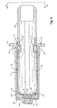
- Figures 2, 4 and 6 illustrate the port 20 and phial 22 in greater detail, Figure 2 showing phial 22 as it is about to be inserted in port 20, Figure 4 showing phial 22 fully inserted in port 20 and Figure 6 being a partial longitudinal section of the fully-inserted phial.
- Phial 22 is a standard and well-known product, having a transparent glass or plastic test-tube like body 42 fitted with a pierceable rubber-like bung 44 and being evacuated.
- Sampling port 20 has an elongate barrel-like body 46 with open top 40 and a closed base 48, the top 40 having an outwardly extending flange 50.
- Spigot 36 extends outwardly from base 48 to connect with sampling tube 34, spigot 36 being moulded onto the butt end of the sampling port needle 52 and being screwed into an internally threaded boss 54 (see particularly Figure 6) formed in the centre of base 48.
- Sampling port needle 52 is encased in a rubber sheath 56, shown extended but with its top cut away in Figure 2 and shown compressed and in section in Figure 6.
- An adsorbent pad 58 is located in the bottom of port 20 on the inner surface of base 48 so as to surround the bottom of needle 52 and sheath 56.
- the barrel 46 of port 20 has opposed semi-cylindrical longitudinally-extending wall portions 60 that, internally, form guide channels 62 ( Figure 2) for guiding phials 22 as the phials are inserted into and withdrawn from port 20.
- Wall portions 60 and phial-guides 62 terminate in shoulders 63 near base 48 that serve to limit the penetration of a phial into the port so that the bung 44 cannot contact pad 58. (See Figure 6).
- FIGS 3, 5 and 7 illustrate the interaction of guard 32 and port 20 in more detail.
- This guard is substantially as disclosed in our aforementioned patents and reference to those patents should be made with regard to its function in relation to needle assembly 24.
- Opposing sides of port barrel 46 form a pair of flat longitudinally extending wall portions 64 running substantially the full length of barrel 46, flats 64 being arranged in quadrature to cylindrical portions 60 of the barrel.
- wall portions 64 form a pair of opposed rectilinear grooves or guide channels 66 ( Figures 2 and 7) which, between them, are adapted to slidingly guide and accommodate the needle guard 32.
- the distance between opposing guard-guides 66 is greater than that between opposing phial-guides 62, so that guard 32 cannot enter or be guided by phial guides 62.
- the upper portion of barrel 46 is diametrically enlarged, as indicated at 68. This allows guard 32 to be inserted into enlargement 68 via port end 40 in any orientation and then rotated about its longitudinal axis to align guard 32 with guard-guides 66. It should be noted that the circumferential width of guard channels 66 is insufficient to allow phials 22 to enter them or to be guided by them.
- a guard 32 can be fully entered into port 20 so that its open end 38 contacts pad 58 at the bottom of the port (see Figure 7), but a phial 22 cannot be entered so far into port 20 because its travel is limited by abutment of its bung 44 with shoulders 63 on phial-guides 62. This prevents bungs 44 of phials 22 from contacting pad 58 and being contaminated by blood in or on the pad.
- the retaining means that retain guard 32 in port 20 simply comprise a tooth-like catch 70 on at least one of the narrow sides 72 of guard 32, catch 70 being adapted to enter a corresponding aperture 74 near the top of either guard-channel 66 of port 20. While catches 70 may be formed on both sides of guard 32, moulding considerations associated with the particular guard disclosed in our above mentioned Australian patents, make it convenient to employ only one catch and to place that catch on the side of the guard that is not hinged. Since apertures 74 are formed on each side of port 20, guard 32 will be retained in the 20 in either of the ways it can be oriented in guide channels 66.
- Adsorbent pad 58 ( Figures 2, 6 and 7) is shaped to fit the bottom of base 48 of port 20, which in this example is generally rectangular (see Figures 2-5), the pad having a central hole that fits closely around the butt 36 and sheath 56 of port needle 52. Pad 58 may be glued in place or held in place by friction. If desired, protrusions (not shown) may be formed on the inside of barrel 46 near base 48 to retain pad 58 in position. Pad 58 can be formed from highly porous cellulose material not unlike blotting paper and treated with sub-micron particles of TiO 2 and/or clay, the particles adhering to individual fibres rather than creating a filling or size that reduces the porosity of the pad.
- the internal surfaces of port 20 near base 48 can be coated or treated with materials known to promote blood-clotting or to assist in immobilising the flow of blood or other aqueous liquids on or along surfaces.
- a simple treatment may be effected by etching the surface of the internal mould from which port 20 is formed, or by the use of plasma discharge within port 20.
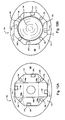
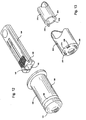
- the second example of the present invention shown in Figures 8 and 9 illustrates the use of an alternative form of retaining means to that of the first example, the needle guard 100 of this example being essentially the same as that (32) of the first example except that it does not have tooth-like catch 70 of that example.
- Guard 100 can be formed by clipping together two similar sub-members 100a and 100b, each having three side recesses 101 on one of their narrow side faces 102 to take corresponding clips (not shown here) on the other narrow side face of the other sub-member, the engagement of the clips and recesses 101 holding the sub-members together.
- sampling port 104 is also of tubular form, but of octagonal section, having a base 106 that has a central internally-threaded boss 108 adapted to take the threaded spigot of a sampling-port needle (not shown).
- port 104 has an open top 110 surrounded by a flange 112.
- flange 112 Immediately below flange 112 are formed four evenly spaced inwardly facing resilient catches 114 that are adapted to enter any one of recesses 101 of a guard 100 that is inserted into port 102.
- recesses 101 and catches 114 form the retaining means.
- the guard is fully inserted into port 104 and the port is so dimensioned that one of catches 114 can enter the central one of recesses 101 when the guard is so inserted.
- port 104 has four internal longitudinally and radially extending ribs 116 that define a pair of channels 118 extending longitudinally between them within which guard 100 can be slidingly guided into port 104 in any one of four orientations so that a respective pair of catches 114 can engage both central recess 101 of guard 100 (see Figure 9).
- the inner faces 116a of ribs 116 also serve to guide a phial 118 - see Figure 10B - into port 100, allowing phial 118 to be removed without the danger of the bung 120 of the phial snagging catches 114.
- the depth of penetration of the phial and guard 100 are both limited by a set of four short ribs 122 upstanding from the inside of the base of port 104 and extending inwards of guide ribs 116 (see Figure 9).
- the inner walls of the port and the exposed surfaces of ribs 116 and 122 near the bottom of the port are roughened and/or coated - as indicated at 124 - to immobilise any blood or droplets of other liquid that comes into contact therewith.
- bottom ribs 112 in between longitudinal guide ribs 116, they will still serve as stops for phial 118 but not as stops for guard 100, so that guard 100 can penetrate to the base of port 104 as in the first example.
- the third example is illustrated in Figure 11 and comprises a tubular needle guard 150 of generally rectangular section and a tubular port 152 of generally circular section.
- Port 152 includes a cylindrical barrel 154 that has a flanged open end 156 and a closed base 158 having a threaded boss 160 into which the butt of a sampling needle (not shown) can be screwed.
- the retaining means comprises a bayonet-type coupling between guard 150 and port 152, guard 150 having a pair of lateral protrusions 162 intermediate of its ends (only one of which is shown in Figure 11) that can enter corresponding radial slots 164 (only one of which is shown) formed in flange 166 of port 152.
- Slots 164 allow protrusions 162 to enter a pair of circumferentially extending slots 168 (only one of which is shown) formed in the upper part of the barrel 154 of port 152.
- a tooth or catch 170 is formed on the underside of flange 166 on each side of slots 164 to retain protrusions 162 against removal, once they have been entered laterally into slots 168 by twisting guard 150 relative to port 152.
- Figure 12 illustrates the fourth example of this invention wherein the retaining means on the guard comprise a pair of laterally-extending and rearwardly-facing teeth or catches 180 formed on the outside of open end 182 of a needle guard 184.
- Needle guard 184 can be otherwise similar to the guard disclosed in our afore-mentioned prior patents.
- the coacting retaining means on the corresponding port 186 comprises an indented catch-band 188 formed around barrel 190 of port 186 near its base 192.
- catch-band 188 serves as a stop to limit the inward travel of a phial but allows the open end 182 of guard 184 to be pushed beyond band 188 until teeth 180 are engaged with the band 188.
- the walls of guard 184 have sufficient flexibility to deform sufficiently to allow teeth 180 to travel beyond catch band 188.
- a plurality of small ratchet-like teeth can be formed on the end of guard 184 instead of the single tooth 180 on each side and a series of narrow corresponding catch-bands can be formed in the inside of port barrel 190 instead of the single large band 188.
- Figure 13 illustrates the fifth example, involving a tubular guard 200 and a tubular sampling port 202.
- guard 200 is one in which the needle mount (not shown) is captured therein, the IV needle (not shown) being extended from the guard for use and withdrawn back into the guard 200 after use.
- guard 200 has an outer dimension that is substantially smaller than the internal diameter of port 202 and the phials (not shown) intended for use in the port.
- the retaining means of this example comprise a pair of clips 204 that extend axially from the open end 206 of guard 200 so as to be adapted to engage a plurality of corresponding pairs of membrane-slots 208 formed in the flat base 210 of port 202.
- Each membrane slot is covered by a thin membrane or 'flash' that can be readily punctured or penetrated by a clip 204.
- guard 202 may have a rectangular shape (as in the other examples) and port 202 may be provided with internal ribs (as in the second example) so that clips 204 are correctly aligned with a pair of slots 208 as guard 200 is pushed into port 204. This has the advantage of preventing clips 204 being broken off or damaged by excessive pressure before they are aligned with slots 208.
- clips like those shown on the needle guard can be formed to upstand from the base of the port so as to enter the open end of a guard such as that of the first example and to retain the guard in the port.
- a single clip of circular form may be used. In any event, such a clip or clips can also serve to limit the penetration of the phials into the port.
Landscapes
- Health & Medical Sciences (AREA)
- Life Sciences & Earth Sciences (AREA)
- Animal Behavior & Ethology (AREA)
- General Health & Medical Sciences (AREA)
- Biophysics (AREA)
- Pathology (AREA)
- Engineering & Computer Science (AREA)
- Biomedical Technology (AREA)
- Heart & Thoracic Surgery (AREA)
- Medical Informatics (AREA)
- Molecular Biology (AREA)
- Public Health (AREA)
- Physics & Mathematics (AREA)
- Hematology (AREA)
- Surgery (AREA)
- Veterinary Medicine (AREA)
- Vascular Medicine (AREA)
- Measurement Of The Respiration, Hearing Ability, Form, And Blood Characteristics Of Living Organisms (AREA)
- Infusion, Injection, And Reservoir Apparatuses (AREA)
- Electrotherapy Devices (AREA)
- Transition And Organic Metals Composition Catalysts For Addition Polymerization (AREA)
- Polymers With Sulfur, Phosphorus Or Metals In The Main Chain (AREA)
- Pharmaceuticals Containing Other Organic And Inorganic Compounds (AREA)
- Acyclic And Carbocyclic Compounds In Medicinal Compositions (AREA)
Claims (21)
- Procédé de réduction du danger de contamination par projection de sang par l'extrémité ouverte (38, 182, 206) d'un organe tubulaire protecteur d'aiguille (32, 100, 150, 184, 200) dans lequel a été retirée une aiguille médicale usée (16), destiné à réduire le danger de projection du sang par l'extrémité ouverte (40, 110, 156) d'un site d'accès d'échantillonnage tubulaire (20, 104, 152, 190, 202) ayant une aiguille usée (52) de site d'accès d'échantillonnage montée à l'intérieur, ou destiné à réduire le danger de blessure par piqûre par l'aiguille (52) du site d'échantillonnage monté dans le site d'échantillonnage (20, 104, 152, 190, 202), le procédé comprenant les étapes d'insertion de l'extrémité ouverte (38, 182, 206) de l'organe protecteur d'aiguille (32, 100, 150, 184, 200) à l'extrémité ouverte du site d'échantillonnage de manière que l'aiguille (52) du site d'échantillonnage pénètre par l'extrémité ouverte (38, 182, 206) de l'organe protecteur (32, 100, 150, 184, 200), et de fixation de l'organe protecteur d'aiguille (32, 100, 150, 184, 200) dans le site d'échantillonnage (20, 104, 152, 190, 202) contre une extraction ou séparation intempestive de celui-ci.
- Procédé selon la revendication 1, dans lequel le site d'échantillonnage (20, 104, 152, 190, 202) a une base fermée (48, 106, 158, 192, 210) sur laquelle est montée l'aiguille (52) du site d'échantillonnage afin qu'elle s'étende axialement dans le site (20, 104, 152, 190, 202), et dans lequel un tampon adsorbant (58) est disposé à l'intérieur du site d'échantillonnage contre la base afin qu'il entoure l'aiguille (52) du site d'échantillonnage, le procédé comprenant l'étape d'insertion de l'organe protecteur d'aiguille (32, 100, 150, 184, 200) dans le site d'échantillonnage afin que l'extrémité ouverte (38, 182, 206) de l'organe protecteur d'aiguille (32, 100, 150, 184, 200) soit juxtaposée au tampon adsorbant (58).
- Appareil destiné à être utilisé dans des opérations médicales intraveineuses (IV), comprenant :un ensemble à aiguille intraveineuse (24) comprenant une aiguille médicale creuse (16) et un tube arrière (28) raccordé à l'aiguille pour la circulation de fluide,un organe tubulaire protecteur d'aiguille (32, 100, 150, 184, 200) ayant une extrémité ouverte (38, 182, 205) dans laquelle l'aiguille (16) peut être retirée après utilisation afin que l'aiguille soit protégée par l'organe protecteur (32, 100, 150, 184, 200),un site tubulaire d'échantillonnage (20, 104, 152, 190, 202) ayant une partie supérieure ouverte (40, 110, 156), une base fermée (48, 106, 158, 192, 210), une dimension latérale pour permettre à l'organe protecteur d'aiguille (32, 100, 150, 184, 200) d'entrer par glissement dans le site (20, 104, 152, 190, 202), etune aiguille creuse (52) de site d'échantillonnage montée dans la base (48, 106, 158, 190, 210) du site (20, 104, 152, 190, 202) afin qu'elle s'étende axialement dans le site, l'aiguille (52) du site d'échantillonnage pouvant être raccordée extérieurement au tube arrière (28) de manière que des échantillons de liquide provenant du tube (28) puissent être retirés avec l'aiguille (52) du site d'échantillonnage, l'appareil étant caractérisé en ce queun dispositif de retenue (70, 74 , 101, 114 , 612, 170 , 180, 188 ; 204, 208) qui agit entre l'organe protecteur (32, 100, 150, 184, 200) et le site (20, 104, 152, 190, 202) est destiné à retenir l'organe protecteur dans le site lorsque l'extrémité ouverte (38, 182, 206) de l'organe protecteur (32, 100, 150, 184, 200) est entrée dans le site (20, 104, 152, 190, 202) et l'aiguille (52) du site d'échantillonnage pénètre à l'extrémité ouverte (38, 182, 206) de l'organe protecteur (32, 100, 150, 184, 200).
- Organe tubulaire protecteur d'aiguille (32, 100, 150, 184, 200) destiné à être utilisé dans des opérations médicales intraveineuses (IV) dans lesquelles un ensemble à aiguille intraveineuse (24), comportant une aiguille creuse (16) et un tube arrière (28) , est raccordé à un site tubulaire d'échantillonnage (20, 104, 152, 190, 202) ayant une partie supérieure ouverte (40, 110, 156), une base fermée (48, 106, 158, 192, 210) et une aiguille creuse (52) de site d'échantillonnage montée dans la base afin qu'elle s'étende axialement dans le site d'échantillonnage (20, 104, 152, 190, 202), l'organe protecteur d'aiguille (32, 100, 150, 184, 200) ayant une extrémité ouverte (38, 182, 206) dans laquelle l'aiguille intraveineuse (16) peut être retirée, l'organe protecteur d'aiguille étant caractérisé en ce que :l'organe protecteur d'aiguille (32, 100, 150, 184, 200) est destiné à être inséré par glissement dans le site d'échantillonnage (20, 104, 152, 190, 202) de manière que l'aiguille (52) du site d'échantillonnage pénètre à l'extrémité ouverte (38, 182, 206) de l'organe protecteur d'aiguille (32, 100, 150, 184, 200), etl'organe protecteur d'aiguille (32, 100, 150, 184, 200) comporte un dispositif de retenue (70, 101, 162, 180, 204) destiné à coopérer avec le site d'échantillonnage (20, 104, 152, 190, 202) lorsque l'organe protecteur (32, 100, 150, 184, 200) est inséré à l'intérieur pour la retenue de l'organe protecteur (32, 100, 150, 184, 200) dans le site d'échantillonnage (20, 104, 152, 190, 202) contre une extraction ou une séparation intempestive de celui-ci.
- Organe protecteur d'aiguille selon la revendication 4, dans lequel le dispositif de retenue comporte un organe d'accrochage par encliquetage (70, 180, 204) placé sur l'organe protecteur (32, 150, 184, 200) ou dans celui-ci et destiné à coopérer avec une saillie ou cavité correspondante (74, 188, 208) formée sur le site d'échantillonnage (20, 190, 202) ou dans celui-ci, ou dans lequel le dispositif de retenue comprend une saillie ou une cavité formée sur l'organe protecteur ou dans celui-ci et destinée à coopérer avec un organe d'accrochage par encliquetage correspondant placé sur le site d'échantillonnage ou dans celui-ci.
- Organe protecteur d'aiguille selon la revendication 4, dans lequel le dispositif de retenue comporte une saillie (162) ou une cavité qui s'étend latéralement sur l'organe protecteur d'aiguille (150) et destinée à coopérer par rotation ou torsion avec une cavité (170) ou saillie correspondante formée sur le site d'échantillonnage (152) ou dans celui-ci.
- Site tubulaire d'échantillonnage destiné à être utilisé dans des opérations médicales intraveineuses (IV), dans lequel un ensemble à aiguille intraveineuse (24) comprenant une siguille creuse (16) et un tube arrière (28) est raccordé au site d'échantillonnage (20, 104, 152, 190, 202) et un organe tubulaire protecteur d'aiguille (32, 100, 150, 184, 200) est utilisé et a une extrémité ouverte (38, 182, 206) dans laquelle peut être retirée l'aiguille intraveineuse (16), le site d'échantillonnage (20, 104, 152, 190, 202) ayant une partie supérieure ouverte (40, 110, 156), une base fermée (48, 106, 158, 192, 210) et une aiguille creuse (52) de site d'échantillonnage montée dans la base afin qu'elle s'étende axialement dans le site, le site d'échantillonnage étant caractérisé en ce que ;le site d'échantillonnage (20, 104, 152, 190, 202) est destiné à loger par coulissement l'organe protecteur d'aiguille (32, 100, 150, 184, 200) à sa partie supérieure ouverte (40, 110, 156) de manière que l'aiguille (52) du site d'échantillonnage pénètre à l'extrémité ouverte (38, 182, 206) de l'organe protecteur d'aiguille (32, 100, 150, 184, 200), etle site d'échantillonnage (20, 104, 152, 190, 202) a un dispositif de retenue (74, 114, 170, 188, 208) destiné à coopérer avec l'organe protecteur d'aiguille (32, 100, 150, 184, 200) lorsque l'organe protecteur est inséré dans le site d'échantillonnage (20, 104, 152, 190, 202) et à retenir l'organe protecteur contre un enlèvement ou une séparation intempestif.
- Site d'échantillonnage selon la revendication 7, dans lequel le dispositif de retenue comporte une cavité (74, 170, 208) ou une saillie (114, 188) disposée sur le site d'échantillonnage (20, 104, 152, 190, 202) ou dans celui-ci et destinée à coopérer avec une saillie (70, 162, 208) ou une cavité (101) correspondante formée sur l'organe protecteur d'aiguille (32, 100, 150, 184, 200) ou dans celui-ci.
- Site d'échantillonnage selon la revendication 7, dans lequel le dispositif de retenue comporte une cavité (170) ou saillie qui s'étend latéralement sur le site d'échantillonnage (152) et destinée à coopérer par rotation ou torsion avec une saillie (162) ou cavité correspondante formée sur l'organe protecteur ou dans celui-ci.
- Site d'échantillonnage selon l'une quelconque des revendications 7 à 9, caractérisé en ce que :un dispositif d'arrêt (63) est disposé à l'intérieur et est destiné à limiter la profondeur à laquelle peut être introduite une fiole sous vide d'échantillon (22, 118) afin que la fiole ne puisse pas être au contact de la base (48, 106, 158, 192, 210) du site (20, 104, 152, 190, 202).
- Site d'échantillonnage selon la revendication 10, dans lequel le dispositif d'arrêt (63) est disposé afin qu'il permette l'introduction d'un organe protecteur d'aiguille (32, 100, 150, 184, 200) dans le site (20, 104, 152, 190, 202) de manière suffisante pour permettre le contact entre l'extrémité ouverte (48, 106, 158, 192, 210) de l'organe protecteur (32, 100, 150, 184, 200) et la base (48, 106, 158, 192, 210) du site (20, 104, 152, 190, 202).
- Site d'échantillonnage selon la revendication 11, caractérisé en ce que :le site comporte à l'intérieur un premier dispositif de guidage (60, 117) destiné à guider une fiole tubulaire d'échantillonnage (22, 118) coaxialement dans le site d'échantillonnage (20, 104, 152, 190, 202) lors de l'insertion par glissement de la fiole d'échantillonnage (22, 118) à l'extrémité ouverte (40, 110, 156) du site,le site contient un second dispositif de guidage (62, 116) destiné à guider l'organe protecteur d'aiguille (32, 100, 150, 184, 200) dans le site (20, 104, 152, 190, 202) lors de l'insertion par glissement de l'organe protecteur (32, 100, 150, 184, 200) dans le site afin que l'aiguille (52) du site d'échantillonnage pénètre à l'extrémité ouverte (38, 182, 206) de l'organe protecteur (32), etle dispositif de retenue (74, 114, 170, 188, 208) est associé au second dispositif de guidage (62) destiné, lors de l'insertion de l'organe protecteur (32, 100, 150, 184, 200) dans le site (20, 104, 152, 190, 202), à coopérer avec l'organe protecteur d'aiguille (32, 100, 150, 184, 200) et à retenir l'organe protecteur dans le site afin qu'il ne puisse pas être retiré ou séparé intempestivement.
- Site d'échantillonnage selon la revendication 12, dans lequel :le site d'échantillonnage (20, 104, 152, 190, 202) a un corps (46) de forme cylindrique,le premier dispositif de guidage comporte une première paire de canaux (62) de guidage qui sont opposés, diamétralement espacés et orientés axialement, formés à l'intérieur du corps (46), chaque canal de la première paire étant un tronçon courbé vers l'extérieur tel qu'une fiole tubulaire d'échantillonnage (22, 118) de section circulaire est guidée axialement par la première paire de canaux (62) lors de l'insertion de la fiole dans le site d'échantillonnage, les canaux (62) de la première paire étant diamétralement espacés à une première distance,le second dispositif de guidage comporte une seconde paire de canaux (66) de guidage qui sont opposés, diamétralement espacés et orientés axialement, formés à l'intérieur du corps (46) en quadrature par rapport à la première paire de canaux (62), les canaux de la seconde paire étant séparés diamétralement l'un de l'autre par une distance supérieure et la première distance, les canaux (66) de la seconde paire étant destinés à guider les côtés d'un organe protecteur d'aiguille (32, 100, 150, 184, 200) lors de l'insertion de l'organe protecteur dans le corps (46) du site d'échantillonnage (20, 104, 152, 190, 202).
- Site d'échantillonnage selon la revendication 13, dans lequel :la première paire de canaux (62) ne s'étend pas vers la base (48, 106, 158, 192, 210) du corps (46) si bien que l'extrémité d'une fiole d'échantillonnage (22, 118) ne peut être au contact de la base (48, 106, 158, 192, 212) après insertion dans la première paire de canaux, etla seconde paire de canaux (66) s'étend suffisamment vers la base (48, 106, 158, 192, 210) pour que l'extrémité de l'organe protecteur d'aiguille (32, 100, 150, 184, 200) puisse être au contact de la base (48, 106, 158, 192, 210) après insertion dans la seconde paire de canaux (66).
- Site d'échantillonnage selon l'une quelconque des revendications 7 à 13, dans lequel un dispositif d'immobilisation de liquide (58, 124) est formé dans le site sur sa base ou près de celle-ci.
- Site d'échantillonnage selon la revendication 15, dans lequel le dispositif d'immobilisation comporte un tampon (58) d'un matériau qui est mouillable par le liquide, le tampon étant disposé dans le site d'échantillonnage (20, 104, 152, 190, 202) de manière qu'il entoure l'aiguille (52) du site d'échantillonnage sur la base.
- Site d'échantillonnage selon la revendication 16, dans lequel le tampon (58) est formé d'un matériau fibreux poreux adsorbant le liquide.
- Site d'échantillonnage selon la revendication 16, dans lequel le tampon (58) est formé d'un matériau de mousse synthétique à cellules ouvertes.
- Site d'échantillonnage selon la revendication 16, dans lequel le tampon (58) est formé d'un matériau céramique poreux.
- Site d'échantillonnage selon la revendication 17, dans lequel le dispositif d'immobilisation comporte une région (124) de la surface interne du site d'échantillonnage entourant l'aiguille du site d'échantillonnage à la base du site d'échantillonnage ou près de cette base, cette région étant revêtue, traitée ou dépolie de manière qu'elle favorise l'adhérence des gouttelettes de liquide sur elle.
- Site d'échantillonnage selon l'une quelconque des revendications 15 à 20, dans lequel le dispositif d'immobilisation est destiné à provoquer la formation rapide d'un caillot sanguin.
Applications Claiming Priority (7)
| Application Number | Priority Date | Filing Date | Title |
|---|---|---|---|
| AUPP4869A AUPP486998A0 (en) | 1998-07-24 | 1998-07-24 | Sample port and needle guard assembly |
| AUPP486998 | 1998-07-24 | ||
| AUPP5722A AUPP572298A0 (en) | 1998-09-04 | 1998-09-04 | Sample port and needle guard assembly - II |
| AUPP572298 | 1998-09-04 | ||
| AUPP659798 | 1998-10-16 | ||
| AUPP6597A AUPP659798A0 (en) | 1998-10-16 | 1998-10-16 | Sample port and needle guard assembly - II |
| PCT/AU1999/000598 WO2000006225A1 (fr) | 1998-07-24 | 1999-07-23 | Protection des aiguilles lors d'intraveineuses |
Publications (3)
| Publication Number | Publication Date |
|---|---|
| EP1107805A1 EP1107805A1 (fr) | 2001-06-20 |
| EP1107805A4 EP1107805A4 (fr) | 2003-04-23 |
| EP1107805B1 true EP1107805B1 (fr) | 2005-04-20 |
Family
ID=27158089
Family Applications (1)
| Application Number | Title | Priority Date | Filing Date |
|---|---|---|---|
| EP99932558A Expired - Lifetime EP1107805B1 (fr) | 1998-07-24 | 1999-07-23 | Protection des aiguilles lors d'intraveineuses |
Country Status (7)
| Country | Link |
|---|---|
| US (1) | US6540696B1 (fr) |
| EP (1) | EP1107805B1 (fr) |
| JP (1) | JP4344477B2 (fr) |
| AT (1) | ATE293390T1 (fr) |
| CA (1) | CA2338628C (fr) |
| DE (1) | DE69924852T2 (fr) |
| WO (1) | WO2000006225A1 (fr) |
Families Citing this family (15)
| Publication number | Priority date | Publication date | Assignee | Title |
|---|---|---|---|---|
| US6387086B2 (en) | 1999-07-29 | 2002-05-14 | Baxter International Inc. | Blood processing set including an integrated blood sampling system |
| US7479131B2 (en) * | 1999-07-29 | 2009-01-20 | Fenwal, Inc. | Biological fluid sampling apparatus, assembly and method |
| AU6498600A (en) | 1999-07-29 | 2001-02-19 | Baxter International Inc. | Sampling tube holder for blood sampling system |
| US6686204B2 (en) * | 2001-08-27 | 2004-02-03 | Becton, Dickinson & Company | Collection device |
| US11083841B2 (en) | 2002-08-09 | 2021-08-10 | Fenwal, Inc. | Needle protector, needle assembly and fluid processing set including the same |
| US7566327B2 (en) | 2002-08-09 | 2009-07-28 | Fenwal, Inc. | Needle protector |
| US7261698B2 (en) * | 2003-04-24 | 2007-08-28 | Sherwood Services Ag | Transfer needle safety apparatus |
| JP4546745B2 (ja) * | 2004-02-19 | 2010-09-15 | 川澄化学工業株式会社 | 血液バッグの構成部品 |
| US20060074348A1 (en) * | 2004-09-30 | 2006-04-06 | Gambro, Inc. | Biologic Fluid Sampling Apparatus |
| JP3123813U (ja) * | 2006-05-17 | 2006-07-27 | 川澄化学工業株式会社 | 真空採血管ホルダ及び医療用具 |
| ES2442628T3 (es) * | 2009-07-01 | 2014-02-12 | Kawasumi Laboratories, Inc. | Equipo de extracción de sangre, soporte de muestra, y cubierta de agujas para evitar la inserción errónea de la aguja |
| US8535257B1 (en) * | 2010-07-07 | 2013-09-17 | Michael S. Zelten | Syringe and swab system |
| US10517519B2 (en) * | 2012-08-31 | 2019-12-31 | Terumo Kabushiki Kaisha | Blood sampling device and blood bag system |
| EP3111976A1 (fr) * | 2015-07-02 | 2017-01-04 | Cliniclab S.L. | Dispositif pour enlever une aiguille d'une seringue et système de prise de sang |
| CN110446465B (zh) | 2017-03-01 | 2022-04-12 | 汾沃有限公司 | 样品管保持器以及采用样品管保持器的系统和方法 |
Family Cites Families (15)
| Publication number | Priority date | Publication date | Assignee | Title |
|---|---|---|---|---|
| DE3049503C2 (de) * | 1980-12-30 | 1983-04-28 | Walter Sarstedt Kunststoff-Spritzgußwerk, 5223 Nümbrecht | "Blutentnahmevorrichtung" |
| SE462464B (sv) | 1987-01-14 | 1990-07-02 | Broden Bengt Inge | Utrustning foer provtagning paa patienter |
| US4932418A (en) | 1987-03-23 | 1990-06-12 | Coburn Timothy J | Needle holder |
| US4784650A (en) | 1987-03-23 | 1988-11-15 | Coburn Timothy J | Needle holder |
| US4943283A (en) * | 1988-07-20 | 1990-07-24 | City Of Hope | Blood collecting apparatus with shielded needles |
| US5514117A (en) * | 1988-09-06 | 1996-05-07 | Lynn; Lawrence A. | Connector having a medical cannula |
| JPH03505293A (ja) * | 1988-09-30 | 1991-11-21 | ウッターバーグ、デビッド,エス | ガードされた翼状針アセンブリ |
| US4900310A (en) * | 1988-10-07 | 1990-02-13 | International Medication Systems Limited | Protective device for cannula used to draw blood |
| US5030209A (en) * | 1988-11-09 | 1991-07-09 | Medical Safety Products, Inc. | Holder for double ended blood collection retractable needle |
| US5086780A (en) | 1990-05-21 | 1992-02-11 | Abbott Laboratories | Blood collection device |
| IL101680A (en) * | 1992-04-23 | 1995-08-31 | Travenol Lab Israel Ltd | Blood sampling device |
| DE4222398C2 (de) | 1992-07-08 | 1994-04-28 | Dieter Wendelborn | Blutentnahmevorrichtung mit verschließbarer Entlüftung |
| US5344417A (en) | 1992-09-11 | 1994-09-06 | Becton, Dickinson And Company | Universal fitting for inoculation receptacles |
| US5782820A (en) | 1996-02-12 | 1998-07-21 | Roland; Patricia D. | Disposable seal for vacutainer holder |
| US5752936A (en) | 1997-02-05 | 1998-05-19 | Chen; Long-Hsiung | Safety vacuum syringe with two opposite needles for blood sampling |
-
1999
- 1999-07-23 EP EP99932558A patent/EP1107805B1/fr not_active Expired - Lifetime
- 1999-07-23 AT AT99932558T patent/ATE293390T1/de not_active IP Right Cessation
- 1999-07-23 DE DE69924852T patent/DE69924852T2/de not_active Expired - Lifetime
- 1999-07-23 CA CA002338628A patent/CA2338628C/fr not_active Expired - Fee Related
- 1999-07-23 US US09/720,053 patent/US6540696B1/en not_active Expired - Lifetime
- 1999-07-23 WO PCT/AU1999/000598 patent/WO2000006225A1/fr not_active Ceased
- 1999-07-23 JP JP2000562075A patent/JP4344477B2/ja not_active Expired - Fee Related
Also Published As
| Publication number | Publication date |
|---|---|
| JP2002521146A (ja) | 2002-07-16 |
| DE69924852T2 (de) | 2006-07-06 |
| EP1107805A4 (fr) | 2003-04-23 |
| CA2338628C (fr) | 2007-12-18 |
| US6540696B1 (en) | 2003-04-01 |
| CA2338628A1 (fr) | 2000-02-10 |
| EP1107805A1 (fr) | 2001-06-20 |
| ATE293390T1 (de) | 2005-05-15 |
| JP4344477B2 (ja) | 2009-10-14 |
| WO2000006225A1 (fr) | 2000-02-10 |
| DE69924852D1 (de) | 2005-05-25 |
Similar Documents
| Publication | Publication Date | Title |
|---|---|---|
| CA2338628C (fr) | Protection des aiguilles lors d'intraveineuses | |
| US7488297B2 (en) | Blood collecting devices | |
| US5084034A (en) | Method for sampling body fluids | |
| CA2417449C (fr) | Aiguilles de securite pour prelevement sanguin | |
| CA2193702C (fr) | Dispositif de transfert de liquide et procede d'utilisation | |
| US5454805A (en) | Medicine vial link for needleless syringes | |
| US6440104B1 (en) | Safety shield assembly | |
| US5088996A (en) | Anti-aerosoling drug reconstitution device | |
| US6017317A (en) | Assembly for collecting blood or other body fluids | |
| CA2077105C (fr) | Capuchon de distributeur de sang et d'autres liquides servant aux fins d'un diagnostic | |
| IL101680A (en) | Blood sampling device | |
| NZ223288A (en) | Single evacuated vessel drives blood sampling device which separates out plasma | |
| WO1995015193A1 (fr) | Clapet de non retour pourvu d'une protection environnementale | |
| US5483973A (en) | Needle stopper and needle removal device | |
| WO2007133951A2 (fr) | Support de sécurité à rentrée par gravité | |
| WO1997047343A1 (fr) | Systeme d'injection hypodermique et procede de maintien du systeme a l'etat sterile avant son utilisation | |
| CA2042695C (fr) | Dispositif universel de securite pour les aiguilles servant aux prelevements sanguins | |
| DK162628B (da) | Blodtagningsudstyr med kanyle, holder og vacuumglas | |
| AU2003200292A1 (en) | Needle holder for use with safety needle assembly | |
| AU691378B2 (en) | Blood sampling unit with protected needle and a method for sampling blood | |
| CA2320783C (fr) | Seringue a aiguille retractable | |
| AU749376B2 (en) | Guarding needles in IV procedures | |
| ZA200101276B (en) | Guarding needles IV procedures. | |
| RU1831341C (ru) | Устройство дл вз ти крови | |
| GB2216801A (en) | Syringe system |
Legal Events
| Date | Code | Title | Description |
|---|---|---|---|
| PUAI | Public reference made under article 153(3) epc to a published international application that has entered the european phase |
Free format text: ORIGINAL CODE: 0009012 |
|
| 17P | Request for examination filed |
Effective date: 20010209 |
|
| AK | Designated contracting states |
Kind code of ref document: A1 Designated state(s): AT BE CH CY DE DK ES FI FR GB GR IE IT LI LU MC NL PT SE |
|
| AX | Request for extension of the european patent |
Free format text: AL;LT;LV;MK;RO;SI |
|
| RIC1 | Information provided on ipc code assigned before grant |
Free format text: 7A 61B 5/14 A, 7A 61M 5/162 B, 7A 61M 5/158 B, 7A 61M 39/10 B |
|
| A4 | Supplementary search report drawn up and despatched |
Effective date: 20030306 |
|
| RIC1 | Information provided on ipc code assigned before grant |
Ipc: 7A 61M 39/10 B Ipc: 7A 61M 5/158 B Ipc: 7A 61M 5/162 B Ipc: 7A 61B 5/15 A |
|
| TCNL | Nl: translation of patent claims filed | ||
| 17Q | First examination report despatched |
Effective date: 20031001 |
|
| GRAP | Despatch of communication of intention to grant a patent |
Free format text: ORIGINAL CODE: EPIDOSNIGR1 |
|
| RIC1 | Information provided on ipc code assigned before grant |
Ipc: 7A 61M 39/10 B Ipc: 7A 61M 5/158 B Ipc: 7A 61M 5/162 B Ipc: 7A 61B 5/14 A |
|
| GRAS | Grant fee paid |
Free format text: ORIGINAL CODE: EPIDOSNIGR3 |
|
| GRAA | (expected) grant |
Free format text: ORIGINAL CODE: 0009210 |
|
| AK | Designated contracting states |
Kind code of ref document: B1 Designated state(s): AT BE CH CY DE DK ES FI FR GB GR IE IT LI LU MC NL PT SE |
|
| PG25 | Lapsed in a contracting state [announced via postgrant information from national office to epo] |
Ref country code: LI Free format text: LAPSE BECAUSE OF FAILURE TO SUBMIT A TRANSLATION OF THE DESCRIPTION OR TO PAY THE FEE WITHIN THE PRESCRIBED TIME-LIMIT Effective date: 20050420 Ref country code: IT Free format text: LAPSE BECAUSE OF FAILURE TO SUBMIT A TRANSLATION OF THE DESCRIPTION OR TO PAY THE FEE WITHIN THE PRESCRIBED TIME-LIMIT;WARNING: LAPSES OF ITALIAN PATENTS WITH EFFECTIVE DATE BEFORE 2007 MAY HAVE OCCURRED AT ANY TIME BEFORE 2007. THE CORRECT EFFECTIVE DATE MAY BE DIFFERENT FROM THE ONE RECORDED. Effective date: 20050420 Ref country code: FI Free format text: LAPSE BECAUSE OF FAILURE TO SUBMIT A TRANSLATION OF THE DESCRIPTION OR TO PAY THE FEE WITHIN THE PRESCRIBED TIME-LIMIT Effective date: 20050420 Ref country code: DK Free format text: LAPSE BECAUSE OF FAILURE TO SUBMIT A TRANSLATION OF THE DESCRIPTION OR TO PAY THE FEE WITHIN THE PRESCRIBED TIME-LIMIT Effective date: 20050420 Ref country code: CH Free format text: LAPSE BECAUSE OF FAILURE TO SUBMIT A TRANSLATION OF THE DESCRIPTION OR TO PAY THE FEE WITHIN THE PRESCRIBED TIME-LIMIT Effective date: 20050420 Ref country code: BE Free format text: LAPSE BECAUSE OF FAILURE TO SUBMIT A TRANSLATION OF THE DESCRIPTION OR TO PAY THE FEE WITHIN THE PRESCRIBED TIME-LIMIT Effective date: 20050420 Ref country code: AT Free format text: LAPSE BECAUSE OF FAILURE TO SUBMIT A TRANSLATION OF THE DESCRIPTION OR TO PAY THE FEE WITHIN THE PRESCRIBED TIME-LIMIT Effective date: 20050420 |
|
| REG | Reference to a national code |
Ref country code: GB Ref legal event code: FG4D |
|
| RIC1 | Information provided on ipc code assigned before grant |
Ipc: 7A 61M 5/162 B Ipc: 7A 61B 5/15 A |
|
| REG | Reference to a national code |
Ref country code: CH Ref legal event code: EP |
|
| REG | Reference to a national code |
Ref country code: IE Ref legal event code: FG4D |
|
| REF | Corresponds to: |
Ref document number: 69924852 Country of ref document: DE Date of ref document: 20050525 Kind code of ref document: P |
|
| PGFP | Annual fee paid to national office [announced via postgrant information from national office to epo] |
Ref country code: MC Payment date: 20050628 Year of fee payment: 7 Ref country code: GR Payment date: 20050628 Year of fee payment: 7 |
|
| PGFP | Annual fee paid to national office [announced via postgrant information from national office to epo] |
Ref country code: IE Payment date: 20050713 Year of fee payment: 7 |
|
| PGFP | Annual fee paid to national office [announced via postgrant information from national office to epo] |
Ref country code: DK Payment date: 20050715 Year of fee payment: 7 |
|
| PG25 | Lapsed in a contracting state [announced via postgrant information from national office to epo] |
Ref country code: SE Free format text: LAPSE BECAUSE OF FAILURE TO SUBMIT A TRANSLATION OF THE DESCRIPTION OR TO PAY THE FEE WITHIN THE PRESCRIBED TIME-LIMIT Effective date: 20050720 Ref country code: GR Free format text: LAPSE BECAUSE OF FAILURE TO SUBMIT A TRANSLATION OF THE DESCRIPTION OR TO PAY THE FEE WITHIN THE PRESCRIBED TIME-LIMIT Effective date: 20050720 |
|
| PG25 | Lapsed in a contracting state [announced via postgrant information from national office to epo] |
Ref country code: CY Free format text: LAPSE BECAUSE OF FAILURE TO SUBMIT A TRANSLATION OF THE DESCRIPTION OR TO PAY THE FEE WITHIN THE PRESCRIBED TIME-LIMIT Effective date: 20050723 |
|
| PG25 | Lapsed in a contracting state [announced via postgrant information from national office to epo] |
Ref country code: ES Free format text: LAPSE BECAUSE OF FAILURE TO SUBMIT A TRANSLATION OF THE DESCRIPTION OR TO PAY THE FEE WITHIN THE PRESCRIBED TIME-LIMIT Effective date: 20050731 |
|
| PGFP | Annual fee paid to national office [announced via postgrant information from national office to epo] |
Ref country code: LU Payment date: 20050805 Year of fee payment: 7 |
|
| PG25 | Lapsed in a contracting state [announced via postgrant information from national office to epo] |
Ref country code: PT Free format text: LAPSE BECAUSE OF FAILURE TO SUBMIT A TRANSLATION OF THE DESCRIPTION OR TO PAY THE FEE WITHIN THE PRESCRIBED TIME-LIMIT Effective date: 20050920 |
|
| REG | Reference to a national code |
Ref country code: CH Ref legal event code: PL |
|
| PLBE | No opposition filed within time limit |
Free format text: ORIGINAL CODE: 0009261 |
|
| STAA | Information on the status of an ep patent application or granted ep patent |
Free format text: STATUS: NO OPPOSITION FILED WITHIN TIME LIMIT |
|
| ET | Fr: translation filed | ||
| 26N | No opposition filed |
Effective date: 20060123 |
|
| PG25 | Lapsed in a contracting state [announced via postgrant information from national office to epo] |
Ref country code: IE Free format text: LAPSE BECAUSE OF NON-PAYMENT OF DUE FEES Effective date: 20060724 |
|
| PG25 | Lapsed in a contracting state [announced via postgrant information from national office to epo] |
Ref country code: MC Free format text: LAPSE BECAUSE OF NON-PAYMENT OF DUE FEES Effective date: 20060731 |
|
| REG | Reference to a national code |
Ref country code: IE Ref legal event code: MM4A |
|
| PG25 | Lapsed in a contracting state [announced via postgrant information from national office to epo] |
Ref country code: LU Free format text: LAPSE BECAUSE OF NON-PAYMENT OF DUE FEES Effective date: 20060723 |
|
| REG | Reference to a national code |
Ref country code: DE Ref legal event code: R082 Ref document number: 69924852 Country of ref document: DE Representative=s name: J D REYNOLDS & CO., GB Ref country code: DE Ref legal event code: R082 Ref document number: 69924852 Country of ref document: DE Representative=s name: MERH-IP MATIAS ERNY REICHL HOFFMANN PATENTANWA, DE Ref country code: DE Ref legal event code: R082 Ref document number: 69924852 Country of ref document: DE |
|
| REG | Reference to a national code |
Ref country code: FR Ref legal event code: PLFP Year of fee payment: 18 |
|
| REG | Reference to a national code |
Ref country code: FR Ref legal event code: PLFP Year of fee payment: 19 |
|
| REG | Reference to a national code |
Ref country code: DE Ref legal event code: R082 Ref document number: 69924852 Country of ref document: DE Representative=s name: MERH-IP MATIAS ERNY REICHL HOFFMANN PATENTANWA, DE |
|
| PGFP | Annual fee paid to national office [announced via postgrant information from national office to epo] |
Ref country code: GB Payment date: 20170626 Year of fee payment: 19 |
|
| PGFP | Annual fee paid to national office [announced via postgrant information from national office to epo] |
Ref country code: NL Payment date: 20170731 Year of fee payment: 19 |
|
| PGFP | Annual fee paid to national office [announced via postgrant information from national office to epo] |
Ref country code: DE Payment date: 20170731 Year of fee payment: 19 Ref country code: FR Payment date: 20170727 Year of fee payment: 19 |
|
| REG | Reference to a national code |
Ref country code: DE Ref legal event code: R119 Ref document number: 69924852 Country of ref document: DE |
|
| REG | Reference to a national code |
Ref country code: NL Ref legal event code: MM Effective date: 20180801 |
|
| GBPC | Gb: european patent ceased through non-payment of renewal fee |
Effective date: 20180723 |
|
| PG25 | Lapsed in a contracting state [announced via postgrant information from national office to epo] |
Ref country code: FR Free format text: LAPSE BECAUSE OF NON-PAYMENT OF DUE FEES Effective date: 20180731 Ref country code: DE Free format text: LAPSE BECAUSE OF NON-PAYMENT OF DUE FEES Effective date: 20190201 Ref country code: GB Free format text: LAPSE BECAUSE OF NON-PAYMENT OF DUE FEES Effective date: 20180723 |
|
| PG25 | Lapsed in a contracting state [announced via postgrant information from national office to epo] |
Ref country code: NL Free format text: LAPSE BECAUSE OF NON-PAYMENT OF DUE FEES Effective date: 20180801 |