EP1108461A2 - Vorrichtung zur Rückgewinnung von Energie - Google Patents
Vorrichtung zur Rückgewinnung von Energie Download PDFInfo
- Publication number
- EP1108461A2 EP1108461A2 EP00310550A EP00310550A EP1108461A2 EP 1108461 A2 EP1108461 A2 EP 1108461A2 EP 00310550 A EP00310550 A EP 00310550A EP 00310550 A EP00310550 A EP 00310550A EP 1108461 A2 EP1108461 A2 EP 1108461A2
- Authority
- EP
- European Patent Office
- Prior art keywords
- cylinder
- energy recovery
- piston
- feed liquid
- valve
- Prior art date
- Legal status (The legal status is an assumption and is not a legal conclusion. Google has not performed a legal analysis and makes no representation as to the accuracy of the status listed.)
- Withdrawn
Links
Images
Classifications
-
- B—PERFORMING OPERATIONS; TRANSPORTING
- B01—PHYSICAL OR CHEMICAL PROCESSES OR APPARATUS IN GENERAL
- B01D—SEPARATION
- B01D61/00—Processes of separation using semi-permeable membranes, e.g. dialysis, osmosis or ultrafiltration; Apparatus, accessories or auxiliary operations specially adapted therefor
- B01D61/02—Reverse osmosis; Hyperfiltration ; Nanofiltration
- B01D61/06—Energy recovery
-
- F—MECHANICAL ENGINEERING; LIGHTING; HEATING; WEAPONS; BLASTING
- F04—POSITIVE - DISPLACEMENT MACHINES FOR LIQUIDS; PUMPS FOR LIQUIDS OR ELASTIC FLUIDS
- F04B—POSITIVE-DISPLACEMENT MACHINES FOR LIQUIDS; PUMPS
- F04B9/00—Piston machines or pumps characterised by the driving or driven means to or from their working members
- F04B9/08—Piston machines or pumps characterised by the driving or driven means to or from their working members the means being fluid
- F04B9/10—Piston machines or pumps characterised by the driving or driven means to or from their working members the means being fluid the fluid being liquid
- F04B9/109—Piston machines or pumps characterised by the driving or driven means to or from their working members the means being fluid the fluid being liquid having plural pumping chambers
- F04B9/117—Piston machines or pumps characterised by the driving or driven means to or from their working members the means being fluid the fluid being liquid having plural pumping chambers the pumping members not being mechanically connected to each other
- F04B9/1176—Piston machines or pumps characterised by the driving or driven means to or from their working members the means being fluid the fluid being liquid having plural pumping chambers the pumping members not being mechanically connected to each other the movement of each piston in one direction being obtained by a single-acting piston liquid motor
-
- Y—GENERAL TAGGING OF NEW TECHNOLOGICAL DEVELOPMENTS; GENERAL TAGGING OF CROSS-SECTIONAL TECHNOLOGIES SPANNING OVER SEVERAL SECTIONS OF THE IPC; TECHNICAL SUBJECTS COVERED BY FORMER USPC CROSS-REFERENCE ART COLLECTIONS [XRACs] AND DIGESTS
- Y02—TECHNOLOGIES OR APPLICATIONS FOR MITIGATION OR ADAPTATION AGAINST CLIMATE CHANGE
- Y02A—TECHNOLOGIES FOR ADAPTATION TO CLIMATE CHANGE
- Y02A20/00—Water conservation; Efficient water supply; Efficient water use
- Y02A20/124—Water desalination
- Y02A20/131—Reverse-osmosis
Definitions
- This invention relates to an energy recovery device particularly but not exclusively for use in combination with reverse osmosis equipment such as is used, for example, in the desalination of water.
- Desalination plants are required to operate at the highest possible efficiency in order to keep the cost of water to a minimum. It is well known to employ energy recovery devices to recover energy from the waste liquor of reverse osmosis equipment. There are various known devices for recovering energy by changing the pressure energy of the waste liquor to shaft work, such as turbines, Pelton wheels and reverse running pumps. However, the conversion of fluid pressure to shaft work and then back again to fluid pressure is inherently less efficient than using fluid pressure directly.
- an energy recovery device comprising at least one cylinder, a piston slidable in the cylinder, first valve means for selectively connecting one end of the cylinder to waste liquid at a first relatively high pressure and to drain, second valve means for allowing feed liquid to enter the other end of the cylinder at a second lower pressure via a feed liquid entry port and to be discharged via a feed liquid discharge port from the other end of the cylinder in response to movement of the piston caused by waste liquid entering said one end of the cylinder, and means ensuring that the area of the piston acting, in use, on the feed liquid is less than the area of the piston, in use, acted upon by the waste liquid so that the piston acts as a pressure intensifier to discharge feed liquid through the feed liquid discharge port at a higher pressure than the pressure of waste liquid entering said one end of the cylinder.
- an energy recovery device comprising a valve housing, a slidable valve element in the valve housing and two cylinders extending from the valve housing in a direction transverse to the axis of movement of the valve element, the slidable valve element controlling the flow of liquid to and from both cylinders.
- a preferred feature of the second aspect of the invention is set forth in claim 15.
- an energy recovery device according to the first or the second aspect of the invention in combination with reverse osmosis equipment.
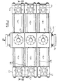
- an energy recovery device comprising three spool valves 10 each having a housing 11 provided with an inlet port 12 which is connected, in use, to a supply of waste liquid discharged from reverse osmosis equipment used, for example, in the desalination of water and an outlet port 13 connected to drain.
- Each spool valve 10 also comprises a linear drive unit 14 for driving a slidable valve element 9 to be described hereinafter.
- the three spool valves 10 are fixed together in side by side relationship by threaded rods 16 extending through the housings 11.
- the energy recovery device also comprises two banks of cylinders 15.
- Each bank comprises three cylinders 15, the cylinders of one bank extending from one side of a respective housing 11 in a direction perpendicular to the axis of movement of the linear drive units 14 and the cylinders of the other bank extending from the other side of a respective housing 11 in an opposite direction.
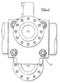
- Each cylinder 15 has a port block 17 at its end remote from its respective spool valve 10.
- Each port block 17 has a feed liquid entry port 18 and a feed liquid discharge port 19.
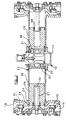
- each cylinder 15 comprises a tubular shell 20 mounted in a recess 21 of a respective housing 11.
- An O-ring seal 22 is provided in a groove in the shell 20 and forms a seal between the housing 11 and the shell 20.
- the other end of each shell 20 is mounted in a recess 23 in a respective port block 17.
- a further O-ring seal 24 is provided in a groove in the shell 20 and provides a seal between the port block 17 and the shell 20.
- Tie rods 25 extend between each valve housing 11 and each port block 17 in order to clamp each shell 20 between a respective housing 11 and a respective port block 17.
- Each cylinder 15 contains a hollow piston 26.
- the end of the piston 26 adjacent to the valve housing 11 is closed, but the other end has an opening which receives a fixed rod 27 extending from the centre of the port block 17.
- the piston 26 is slidable on the rod 27 and a seal 28 is provided between the piston 26 and the rod 27 to prevent flow of liquid between the interior of the hollow piston 26 and the annular space between the rod 27 and the shell 20.
- Each housing 11 has a waste liquid inlet/outlet port 30.
- Each port block 17 has a first non-return valve 31 for preventing feed liquid flowing from the cylinder through the feed liquid entry port 18 and a second non-return valve 32 for preventing liquid entering the cylinder through the feed liquid discharge port 19.
- the interior of the piston 26 communicates with the feed liquid entry port 18 via a through bore 33 in the rod 27.
- the linear drive unit 14 of each spool valve 10 comprises a piston 34 and a cylinder 35.
- the piston 34 is connected to the slidable valve element 9 by a rod 36 and the cylinder has two air ports 37 and 38.
- the slidable valve element 9 is slidable in a sleeve 39 contained within the housing 11.
- the sleeve 39 has a first annular array of openings 40 which communicate with an annular groove 41 in the housing 11 and this annular groove communicates with the liquid inlet/outlet port 30 of the right hand cylinder, as shown in Figure 2.
- the sleeve has a second annular array of openings 42. These openings 42 communicate with an annular groove 43 of the housing 11.
- the annular groove 43 communicates with the inlet port 12.
- the sleeve also has a third annular array of openings 44.
- the openings 44 communicate with an annular groove 45 of the housing 11.
- This annular groove 45 communicates with the waste liquid inlet/outlet port 30 of the left hand cylinder, as shown in Figure 2.
- the valve element 9 has a through bore 46 which is connected to the outlet port 13 of the spool valve 10. It also has three lands 47, 48 and 49.
- the lands 46 and 48 are at opposite ends of the valve element 9 and each have a single annular seal 50 and 51 respectively.
- the central land 47 has two axially spaced seals 52 and 53.
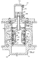
- a first annular groove 54 is defined between the lands 47 and 48 and a second annular groove 55 is defined between the lands 48 and 49. These grooves are in fluid communication with one another via passages 56 in the land 48. As shown, the annular groove 54 communicates with the second annular array of openings 42 in the sleeve 39 and the second annular groove 55 communicates with the third annular array of grooves 44 in the sleeve 39. This places the left hand cylinder 15 in communication with the inlet port 12 and waste liquid discharged from the reverse osmosis equipment flows into the left hand cylinder 15 and moves the piston 26 towards its respective port block 17 to discharge feed liquid from the cylinder through the feed liquid discharge port 19.
- the rod 27 ensures that the area of the piston 26 acting on the feed liquid is less than the area of the piston acted upon by the waste liquid so that the piston acts as a pressure intensifier to discharge feed liquid through the feed liquid discharge port 19 at a higher pressure than the pressure of waste liquid entering the other end of the cylinder.
- the feed liquid can therefore be fed to the reverse osmosis equipment without the need for a booster pump.
- the first annular array of openings 40 communicates with the through bore of the valve element 9 and thus with the outlet port 13. This enables feed liquid to enter the feed liquid entry port 18 of the right hand cylinder 15 and discharge waste liquid from the right hand cylinder 15 to drain via the outlet port 13.
- Air is then admitted to the cylinder 35 through the port 38 while port 37 is vented to atmosphere. This moves the piston 34 upwards and moves the valve element 9 to a position in which the right hand cylinder 15 is connected to a supply of waste liquid discharged from the reverse osmosis equipment and in which the left hand cylinder 15 is connected to drain.
- seals 52 and 53 on the central land 48 of the valve element 9 cut off the supply of waste liquid to the annular grooves 54 and 55 while seals 50 and 51 move across respective annular arrays of apertures 40 and 44. This protects the seals 49 and 50 from damage.
- the timing of the operation of the energy recovery device can be varied by controlling the supply of air to the pistons 34.
- each cylinder 15 is, preferably, no greater than 1.5 metres and is, typically, one metre in length. This is much shorter than the cylinders of conventional work exchanges used to transfer fluid pressure of the waste liquid across a piston.
- the rod 27 may be fixed relative to the piston and may be slidable relative to the end of the cylinder remote from the spool valve housing 11.
- the cylinder could have a stepped diameter bore receiving a stepped diameter piston.
Landscapes
- Engineering & Computer Science (AREA)
- Chemical & Material Sciences (AREA)
- Water Supply & Treatment (AREA)
- Mechanical Engineering (AREA)
- General Engineering & Computer Science (AREA)
- Nanotechnology (AREA)
- Chemical Kinetics & Catalysis (AREA)
- Separation Using Semi-Permeable Membranes (AREA)
- Other Liquid Machine Or Engine Such As Wave Power Use (AREA)
Applications Claiming Priority (2)
| Application Number | Priority Date | Filing Date | Title |
|---|---|---|---|
| GB9929508A GB2357320B (en) | 1999-12-15 | 1999-12-15 | Energy recovery device |
| GB9929508 | 1999-12-15 |
Publications (2)
| Publication Number | Publication Date |
|---|---|
| EP1108461A2 true EP1108461A2 (de) | 2001-06-20 |
| EP1108461A3 EP1108461A3 (de) | 2003-04-16 |
Family
ID=10866270
Family Applications (1)
| Application Number | Title | Priority Date | Filing Date |
|---|---|---|---|
| EP00310550A Withdrawn EP1108461A3 (de) | 1999-12-15 | 2000-11-28 | Vorrichtung zur Rückgewinnung von Energie |
Country Status (5)
| Country | Link |
|---|---|
| US (1) | US6447259B2 (de) |
| EP (1) | EP1108461A3 (de) |
| AU (1) | AU774497B2 (de) |
| CA (1) | CA2328031A1 (de) |
| GB (1) | GB2357320B (de) |
Cited By (5)
| Publication number | Priority date | Publication date | Assignee | Title |
|---|---|---|---|---|
| CN102207067A (zh) * | 2011-05-04 | 2011-10-05 | 全栋(南京)太阳能光伏有限公司 | 推进式清水泵 |
| WO2011151800A3 (en) * | 2010-06-03 | 2012-02-16 | I.D.E. Technologies Ltd. | Flue gas treatment and permeate hardening |
| FR2981704A1 (fr) * | 2011-10-25 | 2013-04-26 | Arkling Ltd | Echangeur de pression volumetrique pour une installation de dessalement d'eau de mer et installation de dessalement |
| EP2837825A1 (de) * | 2013-08-15 | 2015-02-18 | Danfoss A/S | Hydraulikmaschine, insbesondere Hydraulikdruckaustauscher |
| US9556736B2 (en) | 2013-08-15 | 2017-01-31 | Danfoss A/S | Hydraulic machine, in particular hydraulic pressure exchanger |
Families Citing this family (26)
| Publication number | Priority date | Publication date | Assignee | Title |
|---|---|---|---|---|
| US6390785B1 (en) * | 2000-10-05 | 2002-05-21 | The Board Of Governors Of Wayne State University | High efficiency booster for automotive and other applications |
| US20030202892A1 (en) * | 2002-04-30 | 2003-10-30 | Eng-Amr Aly Abdel El Rahman Orfi | Positive displacement pump |
| EP1473308A1 (de) * | 2003-04-28 | 2004-11-03 | B. Braun Melsungen Ag | Stärkederivate zur klinischen, insbesondere parenteralen Anwendung |
| CA2428818A1 (en) * | 2003-05-15 | 2004-11-15 | Ying-Che Huang | Dual-direction pump |
| US7780852B2 (en) * | 2003-07-24 | 2010-08-24 | Effusion Dynamics, Llc | Method for converting kinetic energy of gases or liquids to useful energy, force and work |
| US20070125710A1 (en) * | 2005-12-02 | 2007-06-07 | Craig Schmitt | Non-electric zero waste reverse osmosis water filtering system |
| US20080185045A1 (en) * | 2007-02-05 | 2008-08-07 | General Electric Company | Energy recovery apparatus and method |
| US7740455B1 (en) | 2007-07-09 | 2010-06-22 | Brian Nissen | Pumping system with hydraulic pump |
| US8343338B2 (en) * | 2008-10-09 | 2013-01-01 | Watts Water Technologies, Inc. | Reverse osmosis water filtering system |
| US8123491B2 (en) * | 2009-01-29 | 2012-02-28 | General Electric Company | Methods and systems for energy exchange |
| US20110120928A1 (en) * | 2009-11-25 | 2011-05-26 | Watts Water Technologies, Inc. | Easy change filter assembly for reverse osmosis membrane water purification system |
| US12350627B2 (en) | 2013-02-28 | 2025-07-08 | Aqua Membranes, Inc. | Permeate flow patterns |
| CN105473620B (zh) * | 2013-06-13 | 2018-04-03 | 艾维贝合作公司 | 基于淀粉的水性粘合剂组合物及其应用 |
| JP2019529099A (ja) | 2016-09-20 | 2019-10-17 | アクア メンブレインズ エルエルシー | 透過流パターン |
| KR102033982B1 (ko) | 2016-11-19 | 2019-10-18 | 아쿠아 멤브레인스 엘엘씨 | 나선형 권취 요소를 위한 간섭 패턴 |
| US10780377B2 (en) | 2016-11-30 | 2020-09-22 | Watts Regulator Co. | Sanitizing filter system and method for a residential water filtering system |
| WO2018190937A1 (en) | 2017-04-12 | 2018-10-18 | Aqua Membranes Llc | Graded spacers for filtration wound elements |
| CN120094407A (zh) | 2017-04-20 | 2025-06-06 | 阿夸曼布拉尼斯公司 | 用于螺旋卷绕元件的不嵌套、不变形图案 |
| WO2018195367A1 (en) | 2017-04-20 | 2018-10-25 | Aqua Membranes Llc | Mixing-promoting spacer patterns for spiral-wound elements |
| CN111344053A (zh) | 2017-10-13 | 2020-06-26 | 阿夸曼布拉尼斯公司 | 螺旋缠绕元件的桥支撑件和减少的进给间隔件 |
| CN108425916B (zh) * | 2018-05-08 | 2023-10-13 | 苏州朗瑞水处理设备有限公司 | 高压废液压力能回用设备 |
| WO2020154734A1 (en) | 2019-01-27 | 2020-07-30 | Aqua Membranes Inc. | Composite membranes |
| US12303838B2 (en) | 2019-08-06 | 2025-05-20 | Aqua Membranes, Inc. | Preferred flow paths for spiral-wound elements |
| US11633700B2 (en) | 2020-04-07 | 2023-04-25 | Aqua Membranes Inc. | Independent spacers and methods |
| CN114427521B (zh) * | 2020-09-16 | 2024-02-02 | 中国石油化工股份有限公司 | 正位移式压力能回收装置及回收方法 |
| CN118742376B (zh) | 2021-12-28 | 2025-12-05 | 阿夸曼布拉尼斯公司 | 具有保护特征的高截留率螺旋卷绕元件 |
Family Cites Families (24)
| Publication number | Priority date | Publication date | Assignee | Title |
|---|---|---|---|---|
| GB1148593A (en) * | 1966-04-18 | 1969-04-16 | Albert William Vauds | Hydraulically activated reciprocating motors and pumps |
| US3558242A (en) * | 1969-03-04 | 1971-01-26 | Petersen Candy International L | Pump for desalination plant |
| US3791768A (en) * | 1972-06-16 | 1974-02-12 | W Wanner | Fluid pump |
| US4019838A (en) * | 1975-09-03 | 1977-04-26 | Fluck Henry T | Air pressure-actuated double-acting diaphragm pump with means to produce a selected start-up position |
| US4367140A (en) * | 1979-11-05 | 1983-01-04 | Sykes Ocean Water Ltd. | Reverse osmosis liquid purification apparatus |
| JPS6050171B2 (ja) | 1979-11-12 | 1985-11-07 | 三井化学株式会社 | レゾルシンの製造方法 |
| US4432876A (en) * | 1980-07-30 | 1984-02-21 | Seagold Industries Corporation | Reverse osmosis apparatus and method incorporating external fluid exchange |
| US4386888A (en) * | 1980-09-29 | 1983-06-07 | Mccann's Engineering And Manufacturing Company | Double diaphragm operated reversing valve pump |
| US4637783A (en) * | 1980-10-20 | 1987-01-20 | Sri International | Fluid motor-pumping apparatus and method for energy recovery |
| US4478560A (en) * | 1982-09-23 | 1984-10-23 | The Warren Rupp Company | Fluid-operated reciprocating pump |
| US4627794A (en) * | 1982-12-28 | 1986-12-09 | Silva Ethan A | Fluid pressure intensifier |
| GB8428013D0 (en) * | 1984-11-06 | 1984-12-12 | Flotronics Ag | Double-diaphragm pumps |
| US4820136A (en) * | 1987-06-11 | 1989-04-11 | Saurwein Albert C | Fluid pressure intensifying system |
| US5154820A (en) * | 1987-10-21 | 1992-10-13 | Product Research And Development | Reverse osmosis system with cycled pressure intensifiers |
| JPH07102305B2 (ja) * | 1988-06-29 | 1995-11-08 | 株式会社ササクラ | 逆浸透膜濃縮装置 |
| EP0365805A3 (de) * | 1988-10-22 | 1990-12-05 | Karl Eickmann | Vorrichtung zur Strömungsregelung und eine Hochdruckpumpe |
| US5306428A (en) * | 1992-10-29 | 1994-04-26 | Tonner John B | Method of recovering energy from reverse osmosis waste streams |
| US5500113A (en) * | 1993-10-13 | 1996-03-19 | Shurflo Pump Manufacturing Co. | Reverse osmosis water system |
| US5462414A (en) * | 1995-01-19 | 1995-10-31 | Permar; Clark | Liquid treatment apparatus for providing a flow of pressurized liquid |
| US5628198A (en) * | 1996-05-13 | 1997-05-13 | Permar; Clark | Liquid treatment apparatus for filtering liquid under pressure |
| GB9624205D0 (en) * | 1996-11-21 | 1997-01-08 | Pearson Colin A | Fluid driven pump |
| CA2272339A1 (en) * | 1996-11-21 | 1998-05-28 | Colin Pearson | Fluid driven pumps and apparatus employing such pumps |
| FR2774309B1 (fr) * | 1998-01-30 | 2000-04-21 | Bernard Marinzet | Procede et installation de filtration d'un liquide utilisant un dispositif de filtration a membrane |
| FR2795141B1 (fr) * | 1999-06-15 | 2001-09-07 | Bernard Marinzet | Pompe a pistons, procede et installation de filtration d'eau |
-
1999
- 1999-12-15 GB GB9929508A patent/GB2357320B/en not_active Expired - Fee Related
-
2000
- 2000-11-28 EP EP00310550A patent/EP1108461A3/de not_active Withdrawn
- 2000-12-04 US US09/727,676 patent/US6447259B2/en not_active Expired - Fee Related
- 2000-12-12 CA CA002328031A patent/CA2328031A1/en not_active Abandoned
- 2000-12-14 AU AU72271/00A patent/AU774497B2/en not_active Ceased
Cited By (12)
| Publication number | Priority date | Publication date | Assignee | Title |
|---|---|---|---|---|
| WO2011151800A3 (en) * | 2010-06-03 | 2012-02-16 | I.D.E. Technologies Ltd. | Flue gas treatment and permeate hardening |
| CN102207067A (zh) * | 2011-05-04 | 2011-10-05 | 全栋(南京)太阳能光伏有限公司 | 推进式清水泵 |
| FR2981704A1 (fr) * | 2011-10-25 | 2013-04-26 | Arkling Ltd | Echangeur de pression volumetrique pour une installation de dessalement d'eau de mer et installation de dessalement |
| WO2013061229A3 (fr) * | 2011-10-25 | 2013-07-04 | Arkling Limited | Échangeur de pression volumétrique pour une installation de dessalement d'eau de mer et installation de dessalement |
| CN103890390A (zh) * | 2011-10-25 | 2014-06-25 | 阿克灵有限公司 | 用于海水脱盐装置的容积式压力交换器和脱盐装置 |
| AU2012327971B2 (en) * | 2011-10-25 | 2017-01-19 | Arkling Limited | Volumetric pressure exchanger for a seawater desalination plant and desalination plant |
| CN103890390B (zh) * | 2011-10-25 | 2017-03-08 | 阿克灵有限公司 | 用于海水脱盐装置的容积式压力交换器和脱盐装置 |
| US9700843B2 (en) | 2011-10-25 | 2017-07-11 | Arkling Limited | Volumetric pressure exchanger for a seawater desalination plant and desalination plant |
| EP2837825A1 (de) * | 2013-08-15 | 2015-02-18 | Danfoss A/S | Hydraulikmaschine, insbesondere Hydraulikdruckaustauscher |
| CN104373313A (zh) * | 2013-08-15 | 2015-02-25 | 丹佛斯公司 | 液压机,特别是液压压力交换器 |
| CN104373313B (zh) * | 2013-08-15 | 2016-08-24 | 丹佛斯公司 | 液压机,特别是液压压力交换器 |
| US9556736B2 (en) | 2013-08-15 | 2017-01-31 | Danfoss A/S | Hydraulic machine, in particular hydraulic pressure exchanger |
Also Published As
| Publication number | Publication date |
|---|---|
| GB2357320B (en) | 2004-03-24 |
| GB9929508D0 (en) | 2000-02-09 |
| AU7227100A (en) | 2001-06-21 |
| CA2328031A1 (en) | 2001-06-15 |
| US20010004442A1 (en) | 2001-06-21 |
| GB2357320A (en) | 2001-06-20 |
| AU774497B2 (en) | 2004-07-01 |
| EP1108461A3 (de) | 2003-04-16 |
| US6447259B2 (en) | 2002-09-10 |
Similar Documents
| Publication | Publication Date | Title |
|---|---|---|
| US6447259B2 (en) | Pressure energy recovery device | |
| US6203696B1 (en) | Fluid driven pumps and apparatus employing such pumps | |
| FI61337C (fi) | Hydrauldrivet deplacementpumpsystem | |
| US7214315B2 (en) | Pressure exchange apparatus with integral pump | |
| US20010017278A1 (en) | Equipment for desalination of water by reverse osmosis with energy recovery | |
| JP5964541B2 (ja) | 海水淡水化システムおよびエネルギー交換チャンバー | |
| EP1508361B1 (de) | Umkehrosmose Entsalzungssystem mit einem Druckumwandler | |
| US4913809A (en) | Concentrating apparatus with reverse osmosis membrane | |
| JPH049575B2 (de) | ||
| US20040052639A1 (en) | Rotary work exchanger and method | |
| KR100963557B1 (ko) | 자가 왕복동 에너지 회수 장치 | |
| EP2671014B1 (de) | Geteilter druckbehälter für eine doppelflussverarbeitung | |
| EP1447125B1 (de) | Pumpe für Umkehrosmose-Anlagen zum Entsalzen von Meerwasser | |
| KR20110100472A (ko) | 해수 담수화 시스템의 에너지 회수장치 | |
| KR100838813B1 (ko) | 유압모터의 배출 오일 회수 방법 및 그 장치 | |
| ES2991881T3 (es) | Disposición de ósmosis inversa | |
| EP0430939A1 (de) | Axialsteuerventil | |
| KR20250157677A (ko) | 역삼투압을 이용한 담수화 시스템의 에너지 회수장치 | |
| SU1105687A1 (ru) | Цапфенный распределитель двухр дной радиально-поршневой гидромашины | |
| RU34217U1 (ru) | Гидравлическая система | |
| RU2038132C1 (ru) | Обратноосмотическая установка | |
| ES2329714T3 (es) | Sistema oleodinamico de circuito abierto mejorado para accionar y controlar una bomba de piston de hormigon. | |
| SU1193056A1 (ru) | Гидросистема рулевого управлени транспортного средства |
Legal Events
| Date | Code | Title | Description |
|---|---|---|---|
| PUAI | Public reference made under article 153(3) epc to a published international application that has entered the european phase |
Free format text: ORIGINAL CODE: 0009012 |
|
| AK | Designated contracting states |
Kind code of ref document: A2 Designated state(s): AT BE CH CY DE DK ES FI FR GB GR IE IT LI LU MC NL PT SE TR |
|
| AX | Request for extension of the european patent |
Free format text: AL;LT;LV;MK;RO;SI |
|
| PUAL | Search report despatched |
Free format text: ORIGINAL CODE: 0009013 |
|
| AK | Designated contracting states |
Designated state(s): AT BE CH CY DE DK ES FI FR GB GR IE IT LI LU MC NL PT SE TR |
|
| AX | Request for extension of the european patent |
Extension state: AL LT LV MK RO SI |
|
| RIC1 | Information provided on ipc code assigned before grant |
Ipc: 7F 04B 9/117 B Ipc: 7F 04B 9/115 B Ipc: 7B 01D 61/06 A |
|
| 17P | Request for examination filed |
Effective date: 20030827 |
|
| AKX | Designation fees paid |
Designated state(s): AT BE CH CY DE DK ES FI FR GB GR IE IT LI LU MC NL PT SE TR |
|
| RTI1 | Title (correction) |
Free format text: PRESSURE EXCHANGER |
|
| GRAP | Despatch of communication of intention to grant a patent |
Free format text: ORIGINAL CODE: EPIDOSNIGR1 |
|
| STAA | Information on the status of an ep patent application or granted ep patent |
Free format text: STATUS: THE APPLICATION IS DEEMED TO BE WITHDRAWN |
|
| 18D | Application deemed to be withdrawn |
Effective date: 20060601 |