EP1108541A1 - Tintenstrahlaufzeichnungskopf und tintenstrahlaufzeichnungsvorrichtung - Google Patents
Tintenstrahlaufzeichnungskopf und tintenstrahlaufzeichnungsvorrichtung Download PDFInfo
- Publication number
- EP1108541A1 EP1108541A1 EP99931539A EP99931539A EP1108541A1 EP 1108541 A1 EP1108541 A1 EP 1108541A1 EP 99931539 A EP99931539 A EP 99931539A EP 99931539 A EP99931539 A EP 99931539A EP 1108541 A1 EP1108541 A1 EP 1108541A1
- Authority
- EP
- European Patent Office
- Prior art keywords
- ink
- driving voltage
- change
- jet recording
- ink jet
- Prior art date
- Legal status (The legal status is an assumption and is not a legal conclusion. Google has not performed a legal analysis and makes no representation as to the accuracy of the status listed.)
- Withdrawn
Links
Images



Classifications
-
- B—PERFORMING OPERATIONS; TRANSPORTING
- B41—PRINTING; LINING MACHINES; TYPEWRITERS; STAMPS
- B41J—TYPEWRITERS; SELECTIVE PRINTING MECHANISMS, i.e. MECHANISMS PRINTING OTHERWISE THAN FROM A FORME; CORRECTION OF TYPOGRAPHICAL ERRORS
- B41J2/00—Typewriters or selective printing mechanisms characterised by the printing or marking process for which they are designed
- B41J2/005—Typewriters or selective printing mechanisms characterised by the printing or marking process for which they are designed characterised by bringing liquid or particles selectively into contact with a printing material
- B41J2/01—Ink jet
- B41J2/015—Ink jet characterised by the jet generation process
- B41J2/04—Ink jet characterised by the jet generation process generating single droplets or particles on demand
- B41J2/045—Ink jet characterised by the jet generation process generating single droplets or particles on demand by pressure, e.g. electromechanical transducers
- B41J2/04501—Control methods or devices therefor, e.g. driver circuits, control circuits
- B41J2/04553—Control methods or devices therefor, e.g. driver circuits, control circuits detecting ambient temperature
-
- B—PERFORMING OPERATIONS; TRANSPORTING
- B41—PRINTING; LINING MACHINES; TYPEWRITERS; STAMPS
- B41J—TYPEWRITERS; SELECTIVE PRINTING MECHANISMS, i.e. MECHANISMS PRINTING OTHERWISE THAN FROM A FORME; CORRECTION OF TYPOGRAPHICAL ERRORS
- B41J2/00—Typewriters or selective printing mechanisms characterised by the printing or marking process for which they are designed
- B41J2/005—Typewriters or selective printing mechanisms characterised by the printing or marking process for which they are designed characterised by bringing liquid or particles selectively into contact with a printing material
- B41J2/01—Ink jet
- B41J2/015—Ink jet characterised by the jet generation process
- B41J2/04—Ink jet characterised by the jet generation process generating single droplets or particles on demand
- B41J2/045—Ink jet characterised by the jet generation process generating single droplets or particles on demand by pressure, e.g. electromechanical transducers
- B41J2/04501—Control methods or devices therefor, e.g. driver circuits, control circuits
- B41J2/04581—Control methods or devices therefor, e.g. driver circuits, control circuits controlling heads based on piezoelectric elements
-
- B—PERFORMING OPERATIONS; TRANSPORTING
- B41—PRINTING; LINING MACHINES; TYPEWRITERS; STAMPS
- B41J—TYPEWRITERS; SELECTIVE PRINTING MECHANISMS, i.e. MECHANISMS PRINTING OTHERWISE THAN FROM A FORME; CORRECTION OF TYPOGRAPHICAL ERRORS
- B41J2/00—Typewriters or selective printing mechanisms characterised by the printing or marking process for which they are designed
- B41J2/005—Typewriters or selective printing mechanisms characterised by the printing or marking process for which they are designed characterised by bringing liquid or particles selectively into contact with a printing material
- B41J2/01—Ink jet
- B41J2/015—Ink jet characterised by the jet generation process
- B41J2/04—Ink jet characterised by the jet generation process generating single droplets or particles on demand
- B41J2/045—Ink jet characterised by the jet generation process generating single droplets or particles on demand by pressure, e.g. electromechanical transducers
- B41J2/04501—Control methods or devices therefor, e.g. driver circuits, control circuits
- B41J2/04588—Control methods or devices therefor, e.g. driver circuits, control circuits using a specific waveform
Definitions
- the present invention relates to an ink jet recording head and ink jet recording apparatus and, more particularly, to an ink jet recording head for recording characters or an image on a sheet by generating a pressure change in a pressure chamber filled with ink by using a pressure generation means, and ejecting an ink droplet from a nozzle of the pressure chamber after adding an operation for retracting a meniscus indicating an ink surface of a nozzle opening deep inside the nozzle immediately before the ejection to change a meniscus shape into a concave shape, and an ink jet recording apparatus having this ink jet recording head.
- An ink jet recording head of this type is used for an ink jet recording apparatus used as a printer, plotter, copying apparatus, facsimile apparatus, or the like.
- a pressure chamber having a nozzle for ejecting ink is filled with ink, and a pressure chamber generation means such as a piezoelectric actuator is driven to generate a pressure change in the pressure chamber.
- the ink is ejected from the nozzle to the recording medium such as a sheet by this pressure change, thereby printing desired characters or a desired image.
- a means for ejecting a fine droplet with the diameter smaller than a nozzle diameter by adding a "pull" process to a driving waveform and changing a meniscus shape into a concave shape immediately before the ejection is considered and disclosed in, e.g., Japanese Patent Laid-Open No. 55-17589.
- Figs. 14A to 14C show ejection processes by meniscus control. While no ejection is required, a state shown in Fig. 14A has been kept.
- an electrical pulse is applied to a piezoelectric actuator so as to increase the internal volume of a pressure chamber to change a meniscus shape into a concave shape, as shown in Fig. 14B.
- an electrical pulse is applied to the piezoelectric actuator so as to decrease the internal volume of the pressure chamber to eject an ink droplet, as shown in Fig. 14C.
- a method of changing an ejection ink droplet diameter by changing a "pull" strength and timing is also disclosed in Japanese Patent Laid-Open No. 59-143653.
- an additional pulse voltage application means for applying to a nozzle an additional pulse voltage having a polarity opposite to that of a main pulse voltage to determine the front end position of a liquid before applying the main pulse voltage, and an additional pulse voltage regulation means for regulating a voltage level or width of the additional pulse.
- a main pulse voltage application timing adjustment means for adjusting a timing from the end of additional pulse voltage application to the start of main pulse voltage application.
- a method of stabilizing an ink droplet ejection state by changing a "pull" strength in accordance with the ambient temperature is also disclosed in Japanese Patent Laid-Open No. 2-253960.
- a temperature measurement means for measuring an ink temperature
- an additional pulse voltage regulation means for regulating a voltage level or width of an additional pulse in accordance with the measured temperature.
- An ink jet recording head is an ink jet recording head for generating a pressure change in a pressure chamber filled with ink by using pressure generation means, and ejecting an ink droplet from a nozzle of the pressure chamber after adding an operation for retracting a meniscus deep inside the nozzle immediately before the ejection to change a meniscus shape into a concave shape, wherein a viscosity of the ink within a temperature range in which an apparatus is used is not less than 2 mPa ⁇ s.
- the viscosity of the ink within the temperature range in which the apparatus is used is not more then 6 mPa ⁇ s.
- a temperature detection unit for detecting ambient temperature is included, a driving voltage generated by a driving voltage control unit constructing the pressure generation means is corrected in accordance with a change in the ambient temperature detected by the temperature detection unit, and the viscosity of the ink within the temperature range in which the apparatus is used is not more than 15 mPa ⁇ s.
- a minimum total diameter of the ink droplet is not more than 25 ⁇ m.
- a diameter of the nozzle falls within the range of 20 to 40 ⁇ m.
- a driving voltage generated by the driving voltage control unit and used to change the meniscus shape of the ink into the concave shape is corrected in accordance with a viscosity change in the ink depending on a change in the ambient temperature.
- a driving voltage generated by the driving voltage control unit and used to change the meniscus shape of the ink into the concave shape and a driving voltage generated by the driving voltage control unit and used to eject the ink are corrected in accordance with a viscosity change of the ink depending on a change in the ambient temperature.
- a driving voltage generated by the driving voltage control unit and used to change the meniscus shape of the ink into the concave shape and a driving voltage generated by the driving voltage control unit and used to eject the ink are corrected at the same magnification in accordance with a viscosity change of the ink depending on a change in the ambient temperature.
- a driving voltage generated by the driving voltage control unit and used to change the meniscus shape of the ink into the concave shape does not exceed an offset voltage of a driving waveform.
- An ink jet recording apparatus is an ink jet recording apparatus for printing by generating a pressure change in a pressure chamber filled with ink by using pressure generation means, and ejecting an ink droplet from a nozzle of the pressure chamber after adding an operation for retracting a meniscus deep inside the nozzle immediately before the ejection to change a meniscus shape into a concave shape, wherein a viscosity of the ink within a temperature range in which the apparatus is used is not less than 2 mPa ⁇ s.
- the viscosity of the ink within the temperature range in which the apparatus is used is not more then 6 mPa ⁇ s.
- a temperature detection unit for detecting ambient temperature is included, a driving voltage generated by a driving voltage control unit constructing the pressure generation'means is corrected in accordance with a change in the ambient temperature detected by the temperature detection unit, and the viscosity of the ink within the temperature range in which the apparatus is used is not more than 15 mPa ⁇ s.
- a driving voltage generated by the driving voltage control unit and used to change the meniscus shape of the ink into the concave shape is corrected in accordance with a viscosity change in the ink depending on a change in the ambient temperature.
- a driving voltage generated by the driving voltage control unit and used to change the meniscus shape of the ink into the concave shape and a driving voltage generated by the driving voltage control unit and used to eject the ink are corrected in accordance with a viscosity change of the ink depending on a change in the ambient temperature.
- a driving voltage generated by the driving voltage control unit and used to change the meniscus shape of the ink into the concave shape and a driving voltage generated by the driving voltage control unit and used to eject the ink are corrected at the same magnification in accordance with a viscosity change of the ink depending on a change in the ambient temperature.
- a driving voltage generated by the driving voltage control unit and used to change the meniscus shape of ink into the concave shape does not exceed an offset voltage of a driving waveform.
- Fig. 1 is a sectional view showing the arrangement of an ink jet recording apparatus according to the first embodiment of the present invention.
- An ink jet recording apparatus is used as a printer, plotter, copying apparatus, facsimile apparatus, or the like.
- the ink jet recording apparatus shown in Fig. 1 is a printer and includes a sheet hopper 1, ink jet recording head 3, sheet stacker 4, control unit 5, and interface unit 6.
- the ink jet recording head 3 is attached to a carrier (not shown).
- the ink jet recording head 3 scans in a direction perpendicular to the convey direction of a sheet 2.
- the sheet 2 is supplied from the sheet hopper 1, and desired characters and image are printed on the sheet 2 by the ink jet recording head 3.
- the printed sheet 2 is then discharged to the sheet stacker 4.
- the control unit 5 controls these operations.
- the interface unit 6 is connected to a host apparatus such as a personal computer to receive the signal from the host apparatus.
- the interface unit 6 is connected to a communication line, and the apparatus includes a scanner for inputting an image to be transmitted.
- the apparatus includes a scanner for inputting an image to be copied.
- the interface unit 6 may not be required.
- Fig. 2 is a block diagram showing the arrangement of the ink jet recording head 3.
- Ink stored in an ink tank 11 passes through a supply path 12 and supply port 13 and fills a pressure chamber 14.
- a piezoelectric actuator 15 vibrates a vibration plate 17 by receiving a voltage from a driving voltage control unit 16.
- the vibration plate 17 is vibrated, the volume of the pressure chamber 14 changes, and the ink in the pressure chamber 14 is ejected from a nozzle 18 toward to the sheet 2.
- a total ejection ink droplet diameter need be set at 25 ⁇ m or less. This means that a point at which the human eye does not perceive coarse grains is close to a total ejection ink droplet diameter of 25 ⁇ m, and becomes an index when an ink jet recording head or ink jet recording apparatus is designed.
- a total ejection ink droplet diameter is a converted diameter when the volume of a combination of a main droplet and satellite (a fine particle occurring around the main droplet) is regarded as a sphere.
- a nozzle diameter is made to small, the total diameter of a possible minimum ink droplet is set small.
- the nozzle tends to clog caused by drying ink, mixing dust, or the like, thereby degrading the reliability of the ink jet recording head.
- manufacturing difficulty increases so that manufacturing variation occurs between nozzles, the ink droplet ejection speeds and droplet diameters (main droplet diameter and satellite diameter) vary between the nozzles or the ink jet recording apparatuses at a high probability or rate.
- the nozzle diameter is made smaller while paying attention to only the maximum ink droplet, the ejection of the maximum ink droplet corresponding to the desired resolution becomes difficult. Accordingly, the nozzle diameter has a practical lower limit.
- the natural period of a pressure wave in the pressure chamber 14 in a state in which the pressure chamber 14 is filled with the ink is set within the range of 5 to 30 ⁇ sec, and most preferably, within the range of 5 to 20 ⁇ sec.
- the natural period is preferably decreased, however, a decrease in natural period makes it difficult to eject the large ink droplet. For this reason, the natural period of the pressure wave in the pressure chamber 14 is set in the range described above, thereby ejecting the small to large droplets with good balance.
- a decrease in thickness of the vibration plate 17 improves an efficiency of conversion from the driving energy to a pressure. Since, however, the thin vibration plate 17 is difficult to manufacture, its thickness is preferably set within the range of 10 to 50 ⁇ m.
- the piezoelectric actuator 15 has about ten layers each having an inner electrode formed on a piezoelectric material having a predetermined thickness and stacked.
- the thickness of the piezoelectric material layer is decided in accordance with a driving voltage applied from a driving power source.
- the driving voltage is about 40 V
- the thickness of one layer is preferably set at about 40 ⁇ m.
- the total diameter of a possible minimum ink droplet can be decreased at most to a size equal to that of the nozzle diameter.
- the "pull" process need be added to the driving waveform.
- Fig. 3 is a view showing a driving waveform voltage input to a piezoelectric actuator.
- a meniscus shape is changed into a concave shape at the pull portion of 1 ⁇ , and the ink droplet is ejected by applying an ejection energy shown at the push portion of 2 ⁇ at a predetermined timing.
- a fine droplet having a size smaller than that of the nozzle diameter can be ejected by meniscus control in which the "pull" and "push” processes are performed.
- the range in which the ejection ink droplet diameter can be changed can be widened, and as needed, the driving waveform added with the "pull” process is used. Accordingly, a dot diameter is modulated in the multiple levels ranging from a fine droplet having a diameter smaller than that of the nozzle to a large droplet generating no gap between dots upon solid-printing, thereby implementing graytone printing in a wide density range.
- the diameter of a nozzle to be used also has an upper limit to satisfy the restriction on the minimum ink droplet setting, in which the total droplet diameter is set at 25 ⁇ m or less.
- the present inventors manufactured a recording head whose nozzle was changed between the 10 ⁇ m to 60 ⁇ m and conducted an ink droplet ejection experiment.
- the present inventors examined the manufacturing reliability described above and stability of ink jet recording head performance, and the restriction on the minimum ink droplet described above. As a result, it was obvious that an appropriate nozzle diameter satisfying these conditions fell within the range of 20 ⁇ m to 40 ⁇ m.
- the present inventors pay attention to an ink viscosity change that is considered as a large variation factor for the retraction amount of the meniscus.
- the ink viscosity is greatly varied with respect to the ambient temperature such as an environmental temperature in which the apparatus is installed or a temperature in the apparatus. As shown in Fig. 13, for example, when the ink temperature raises from 5°C to 40°C, the ink viscosity decreases from 5.5 mPa ⁇ s to 1,5 mPa ⁇ s.
- the present inventors examined first specific influences of various types of phenomena occurring at near the nozzle on the ink viscosity change, and confirmed the following facts. Since the ink fluidity becomes high upon decreasing the ink viscosity, an action on the meniscus surface becomes unstable stepwisely. In particularly, when the ink viscosity becomes less than 2 mPa ⁇ s, the influence in droplet formation becomes conspicuous. In this state, not only the diameters of the main droplet and satellite and the speed of them become unstable, but the abnormally ejected satellite attaches to a nozzle plate to cause an ejection failure. In some cases, the unstable state stops ejection.
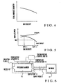
- Fig. 4 is a graph showing a change in total ejection droplet diameter when an ink viscosity is changed
- Fig. 5 is a graph showing a change in ejected ink droplet speed when the ink viscosity is changed. Referring to Figs. 4 and 5, upon increasing the ink viscosity, the total droplet diameter decreases, the main droplet speed decreases, and the satellite speed increases. At the point where the magnitudes of the main droplet speed and satellite speed cross each other, the ink viscosity is 2 mPa ⁇ s.
- the viscosity of ink to be used need have the lower limit of 2 mPa ⁇ s.
- the ink viscosity of ink to be used need have the upper limit of 6 mPa ⁇ s, as described in Fig. 5.
- the ink viscosity within the temperature range in which the apparatus is used is obviously set within the range of 2 to 6 mPa ⁇ s, thereby stably ejecting a fine droplet with the total droplet diameter of as small as 25 ⁇ m or less.
- a viscosity modifier is generally added to ink.
- a polyvalent alcohol compound is frequently used.
- polyethylene glycol the molecular weight of 200 to 800
- polyethylene glycol the molecular weight of 200 to 800
- the content of the viscosity modifier to be added is changed depending on a solvent of ink or the other additives, however, the viscosity modifier is generally added in an amount of about 0.1 to 10% with respect to the ink amount.
- the second embodiment of the present invention will be described below.
- the second embodiment is different from the first embodiment in the arrangement of the ink jet recording head and a driving voltage control scheme.
- Fig. 6 is a block diagram showing an arrangement of an ink jet recording head according to the second embodiment, in which a temperature detection unit 19 is included in addition to the arrangement of the ink jet recording head according to the first embodiment shown in Fig. 2.
- Fig. 7 is a view showing a driving waveform voltage input to a piezoelectric actuator. Excepting for the ejection operation time, an offset voltage V0 is kept applied to the piezoelectric actuator.
- Reference symbol V1 denotes a "pull” voltage; and V2, a "push” voltage.
- Reference symbols tl to t6 denote the times. If the value of V1 is set large in addition to the V0, a portion at which the driving waveform voltage shifts from positive to negative voltages is formed. When the piezoelectric actuator is driven under this condition, a polarized state of the piezoelectric actuator is inversed. This causes a phenomenon in which the displacement of the piezoelectric actuator is greatly decreased in the subsequently driving. In addition, the cost of a power source for driving the ink jet recording head increases because both positive and negative voltages are required. Thus, the value of V1 is preferably set without exceeding the value of V0.
- the inspection is performed at a portion where the ink viscosity is high.
- the ink viscosity is increased while changing the correction factor such that the main droplet speed becomes constant, as shown in Fig. 12, the total droplet diameter tends to slightly decrease. This means that a thinner liquid column is produced by increasing the curvature of the central portion of a meniscus with an increase in ink viscosity.
- the total droplet diameter discontinuously increases at a point where the ink viscosity is 15 mPa ⁇ s.
- the total droplet diameter also increases upon increasing the ink viscosity.
- the second satellite is undesirably given the energy enough to be ejected from the nozzle by increasing the correction factor upon increasing the ink viscosity, i.e., by increasing the driving waveform voltage.
- the second satellite is mainly produced by a pressure wave reaction and has a droplet speed very slower than that of the main droplet or a first satellite, and a diameter larger than that of the main droplet or a first satellite. The second satellite production thus greatly degrades image quality. Accordingly, the upper limit of the viscosity of ink to be used is 15 mPa ⁇ s.
- the ink viscosity within the temperature range in which the apparatus is used is set within the range of 2 to 15 mPa ⁇ s. With this setting, even a fine droplet such as a droplet having a total droplet diameter of 25 ⁇ m or less can be stably ejected with the constant droplet speed and predetermined or smaller total droplet diameter.
- the ink viscosity within the temperature range in which the apparatus is used is set within the range of 2 to 6 mPa ⁇ s.
- the ink viscosity within the temperature range in which the apparatus is used is set within the range of 2 to 15 mPa ⁇ s.
Landscapes
- Ink Jet (AREA)
- Particle Formation And Scattering Control In Inkjet Printers (AREA)
Applications Claiming Priority (3)
| Application Number | Priority Date | Filing Date | Title |
|---|---|---|---|
| JP21416498 | 1998-07-29 | ||
| JP21416498 | 1998-07-29 | ||
| PCT/JP1999/003994 WO2000006387A1 (fr) | 1998-07-29 | 1999-07-26 | Tete d'enregistrement a jet d'encre et enregistreur a jet d'encre |
Publications (2)
| Publication Number | Publication Date |
|---|---|
| EP1108541A1 true EP1108541A1 (de) | 2001-06-20 |
| EP1108541A4 EP1108541A4 (de) | 2001-10-24 |
Family
ID=16651303
Family Applications (1)
| Application Number | Title | Priority Date | Filing Date |
|---|---|---|---|
| EP99931539A Withdrawn EP1108541A4 (de) | 1998-07-29 | 1999-07-26 | Tintenstrahlaufzeichnungskopf und tintenstrahlaufzeichnungsvorrichtung |
Country Status (4)
| Country | Link |
|---|---|
| US (1) | US6467865B1 (de) |
| EP (1) | EP1108541A4 (de) |
| AU (1) | AU4801299A (de) |
| WO (1) | WO2000006387A1 (de) |
Cited By (1)
| Publication number | Priority date | Publication date | Assignee | Title |
|---|---|---|---|---|
| EP1431035A1 (de) * | 2002-12-16 | 2004-06-23 | Xerox Corporation | Tintenstrahlgerät |
Families Citing this family (16)
| Publication number | Priority date | Publication date | Assignee | Title |
|---|---|---|---|---|
| JP3159188B2 (ja) * | 1998-10-20 | 2001-04-23 | 日本電気株式会社 | インクジェット記録ヘッドの駆動方法 |
| JP3659494B2 (ja) * | 2001-05-16 | 2005-06-15 | セイコーエプソン株式会社 | 液体噴射装置 |
| US7059699B2 (en) * | 2001-07-20 | 2006-06-13 | Seiko Epson Corporation | Ink tank with data storage for drive signal data and printing apparatus with the same |
| ATE409587T1 (de) * | 2001-08-29 | 2008-10-15 | Seiko Epson Corp | Flüssigkeitsstrahlvorrichtung und verfahren zu deren steuerung |
| US7018022B2 (en) * | 2002-06-12 | 2006-03-28 | Sharp Kabushiki Kaisha | Inkjet printhead and inkjet image apparatus |
| JP2004042576A (ja) * | 2002-07-16 | 2004-02-12 | Ricoh Co Ltd | ヘッド駆動制御装置及び画像記録装置 |
| JP2004299097A (ja) * | 2003-03-28 | 2004-10-28 | Seiko Epson Corp | 液滴吐出装置、電気光学装置、電子機器、電気光学装置の製造方法、液滴吐出装置の吐出制御方法 |
| US8491076B2 (en) | 2004-03-15 | 2013-07-23 | Fujifilm Dimatix, Inc. | Fluid droplet ejection devices and methods |
| US7281778B2 (en) | 2004-03-15 | 2007-10-16 | Fujifilm Dimatix, Inc. | High frequency droplet ejection device and method |
| EP1836056B1 (de) | 2004-12-30 | 2018-11-07 | Fujifilm Dimatix, Inc. | Tintenstrahldruck |
| JP2008149703A (ja) * | 2006-11-23 | 2008-07-03 | Ricoh Co Ltd | 画像形成装置及び印刷物 |
| US7988247B2 (en) | 2007-01-11 | 2011-08-02 | Fujifilm Dimatix, Inc. | Ejection of drops having variable drop size from an ink jet printer |
| JP2010158843A (ja) * | 2009-01-08 | 2010-07-22 | Seiko Epson Corp | 液体吐出装置、及び、その制御方法 |
| JP2010179539A (ja) * | 2009-02-04 | 2010-08-19 | Seiko Epson Corp | 液体噴射装置及び液体噴射ヘッドの駆動方法 |
| US8393702B2 (en) | 2009-12-10 | 2013-03-12 | Fujifilm Corporation | Separation of drive pulses for fluid ejector |
| JP5904395B2 (ja) * | 2011-07-14 | 2016-04-13 | 株式会社リコー | 液滴吐出ヘッド、インクカートリッジ及び画像形成装置 |
Family Cites Families (31)
| Publication number | Priority date | Publication date | Assignee | Title |
|---|---|---|---|---|
| JPS51137506A (en) * | 1975-05-22 | 1976-11-27 | Konishiroku Photo Ind | Composition of ink for ink jet recording |
| JPS5517589A (en) | 1978-07-27 | 1980-02-07 | Seiko Epson Corp | Ink jet driving method for ink jet recording device |
| JPS59143653A (ja) | 1983-02-05 | 1984-08-17 | Konishiroku Photo Ind Co Ltd | 液体放出装置 |
| JPS59176055A (ja) * | 1983-03-25 | 1984-10-05 | Konishiroku Photo Ind Co Ltd | オンデマンド型インクジエツト記録装置 |
| JPS6235849A (ja) * | 1985-08-09 | 1987-02-16 | Canon Inc | インクジエツト記録法 |
| JPS62240555A (ja) * | 1986-04-14 | 1987-10-21 | Canon Inc | 液体噴射記録方法 |
| JPS631580A (ja) * | 1986-06-20 | 1988-01-06 | Canon Inc | インクジエツト記録方法 |
| JPS6371355A (ja) | 1986-09-12 | 1988-03-31 | Fujitsu Ltd | インクジエツトヘツドの駆動方法 |
| JP2593940B2 (ja) | 1988-10-14 | 1997-03-26 | 富士電機株式会社 | インクジェット記録ヘッドの駆動方法 |
| JPH02253960A (ja) * | 1989-03-29 | 1990-10-12 | Canon Inc | 液体噴射記録装置 |
| US5130726A (en) | 1989-02-28 | 1992-07-14 | Canon Kabushiki Kaisha | Ink jet recording apparatus |
| US5461403A (en) | 1991-08-16 | 1995-10-24 | Compaq Computer Corporation | Droplet volume modulation techniques for ink jet printheads |
| JPH0631932A (ja) * | 1992-07-14 | 1994-02-08 | Fuji Xerox Co Ltd | インクジェット記録装置 |
| GB9306680D0 (en) * | 1993-03-31 | 1993-05-26 | The Technology Partnership Ltd | Fluid droplet apparatus |
| JP3356187B2 (ja) | 1993-04-23 | 2002-12-09 | セイコーエプソン株式会社 | インクジェットヘッド及びその駆動方法 |
| US5644341A (en) * | 1993-07-14 | 1997-07-01 | Seiko Epson Corporation | Ink jet head drive apparatus and drive method, and a printer using these |
| JP3503656B2 (ja) | 1993-10-05 | 2004-03-08 | セイコーエプソン株式会社 | インクジェットヘッドの駆動装置 |
| JP3117854B2 (ja) * | 1993-11-02 | 2000-12-18 | キヤノン株式会社 | インクジェット装置および該装置用インクジェットヘッドの制御方法 |
| GB9405137D0 (en) * | 1994-03-16 | 1994-04-27 | Xaar Ltd | Improvements relating to pulsed droplet deposition apparatus |
| DE69526145T2 (de) * | 1994-06-17 | 2002-08-22 | Canon Kk | Tintenstrahlaufzeichnungsverfahren und Gerät mit Auflösungsumwandlungskapazität |
| JP3356202B2 (ja) | 1996-07-09 | 2002-12-16 | セイコーエプソン株式会社 | インクジェット記録装置 |
| US6217159B1 (en) | 1995-04-21 | 2001-04-17 | Seiko Epson Corporation | Ink jet printing device |
| JPH09169111A (ja) * | 1995-12-20 | 1997-06-30 | Brother Ind Ltd | インクジェットプリンタ |
| JP3249735B2 (ja) * | 1996-01-25 | 2002-01-21 | ブラザー工業株式会社 | インク噴射装置およびその駆動方法 |
| JPH09194780A (ja) | 1996-01-18 | 1997-07-29 | Canon Inc | インク、これを用いたインクジェット記録方法及びインクジェット記録装置 |
| JP3491187B2 (ja) | 1996-02-05 | 2004-01-26 | セイコーエプソン株式会社 | インクジェット式記録装置による記録方法 |
| JP3531347B2 (ja) | 1996-04-16 | 2004-05-31 | セイコーエプソン株式会社 | インクジェット式記録装置 |
| JPH1034914A (ja) * | 1996-07-25 | 1998-02-10 | Minolta Co Ltd | インクジェット記録ヘッド |
| JPH10166567A (ja) | 1996-12-12 | 1998-06-23 | Minolta Co Ltd | インクジェット記録装置 |
| JPH10193620A (ja) | 1997-01-09 | 1998-07-28 | Minolta Co Ltd | インクジェットヘッド |
| US6109716A (en) * | 1997-03-28 | 2000-08-29 | Brother Kogyo Kabushiki Kaisha | Ink-jet printing apparatus having printed head driven by ink viscosity dependent drive pulse |
-
1999
- 1999-07-26 EP EP99931539A patent/EP1108541A4/de not_active Withdrawn
- 1999-07-26 US US09/744,475 patent/US6467865B1/en not_active Expired - Fee Related
- 1999-07-26 WO PCT/JP1999/003994 patent/WO2000006387A1/ja not_active Ceased
- 1999-07-26 AU AU48012/99A patent/AU4801299A/en not_active Abandoned
Cited By (1)
| Publication number | Priority date | Publication date | Assignee | Title |
|---|---|---|---|---|
| EP1431035A1 (de) * | 2002-12-16 | 2004-06-23 | Xerox Corporation | Tintenstrahlgerät |
Also Published As
| Publication number | Publication date |
|---|---|
| US6467865B1 (en) | 2002-10-22 |
| WO2000006387A1 (fr) | 2000-02-10 |
| AU4801299A (en) | 2000-02-21 |
| EP1108541A4 (de) | 2001-10-24 |
Similar Documents
| Publication | Publication Date | Title |
|---|---|---|
| US6467865B1 (en) | Ink jet recording head and ink jet recorder | |
| EP0739742B1 (de) | Aufzeichnungsgerät mit Flüssigkeitsstrahl zur Aufzeichnung von Abbildungen in Halbtondichte | |
| US5552809A (en) | Method for driving ink jet recording head and apparatus therefor | |
| US6357846B1 (en) | Ink jet recording apparatus and recording method using the same | |
| EP1620269B1 (de) | Bildreproduzier-/-erzeugungsvorrichtung mit unter verbesserter steuerungswellenform betriebenem druckkopf | |
| CN100420574C (zh) | 图像形成装置 | |
| JP5824828B2 (ja) | 画像形成装置、画像補正方法および画像補正プログラム | |
| US7585044B2 (en) | Method for normalizing a printhead assembly | |
| JP2012179842A (ja) | 画像形成装置、画像補正方法、画像補正プログラムおよび画像形成システム | |
| JP2947237B2 (ja) | 画像記録装置 | |
| EP3321087B1 (de) | Tintenstrahlaufnahmevorrichtung und tintenstrahlaufnahmeverfahren | |
| US8348369B2 (en) | Image forming method and image forming apparatus | |
| US6257687B1 (en) | Method for driving ink jet printing head and circuits of the same | |
| JP2000071437A (ja) | インクジェット記録装置及び記憶媒体並びに制御テーブル作成方法 | |
| US6290317B1 (en) | Inkjet printing apparatus | |
| JP6079037B2 (ja) | 画像形成装置、画像形成方法、プログラムおよび記録媒体 | |
| JP2008302652A (ja) | 圧電素子の特性情報付与方法、及び、液体噴射装置 | |
| JP2000103061A (ja) | インクジェット記録ヘッドおよびインクジェット記録装置 | |
| JP2006255974A (ja) | 液滴吐出記録ヘッドの駆動方法及び液滴吐出記録装置 | |
| JP2007216576A (ja) | ヘッド補正方法、液滴吐出方法、及び液滴吐出装置 | |
| JP2002254625A (ja) | インクジェット記録装置 | |
| JPWO2000006387A1 (ja) | インクジェット記録ヘッドおよびインクジェット記録装置 | |
| KR100858987B1 (ko) | 화상 형성 방법 및 잉크젯 인쇄 장치 | |
| JP2006082376A (ja) | 液体吐出ヘッドの駆動装置及び画像形成装置 | |
| JPH10250068A (ja) | インクジェット記録装置 |
Legal Events
| Date | Code | Title | Description |
|---|---|---|---|
| PUAI | Public reference made under article 153(3) epc to a published international application that has entered the european phase |
Free format text: ORIGINAL CODE: 0009012 |
|
| 17P | Request for examination filed |
Effective date: 20010220 |
|
| AK | Designated contracting states |
Kind code of ref document: A1 Designated state(s): AT BE CH CY DE DK ES FI FR GB GR IE IT LI LU MC NL PT SE |
|
| A4 | Supplementary search report drawn up and despatched |
Effective date: 20010907 |
|
| AK | Designated contracting states |
Kind code of ref document: A4 Designated state(s): AT BE CH CY DE DK ES FI FR GB GR IE IT LI LU MC NL PT SE |
|
| 17Q | First examination report despatched |
Effective date: 20020327 |
|
| RAP1 | Party data changed (applicant data changed or rights of an application transferred) |
Owner name: FUJI XEROX CO., LTD. |
|
| STAA | Information on the status of an ep patent application or granted ep patent |
Free format text: STATUS: THE APPLICATION IS DEEMED TO BE WITHDRAWN |
|
| 18D | Application deemed to be withdrawn |
Effective date: 20021008 |