EP1108619B1 - Connecteur rotatif - Google Patents
Connecteur rotatif Download PDFInfo
- Publication number
- EP1108619B1 EP1108619B1 EP00127050A EP00127050A EP1108619B1 EP 1108619 B1 EP1108619 B1 EP 1108619B1 EP 00127050 A EP00127050 A EP 00127050A EP 00127050 A EP00127050 A EP 00127050A EP 1108619 B1 EP1108619 B1 EP 1108619B1
- Authority
- EP
- European Patent Office
- Prior art keywords
- rotor
- housing
- rotary connector
- steering wheel
- projections
- Prior art date
- Legal status (The legal status is an assumption and is not a legal conclusion. Google has not performed a legal analysis and makes no representation as to the accuracy of the status listed.)
- Expired - Lifetime
Links
Images

Classifications
-
- H—ELECTRICITY
- H01—ELECTRIC ELEMENTS
- H01R—ELECTRICALLY-CONDUCTIVE CONNECTIONS; STRUCTURAL ASSOCIATIONS OF A PLURALITY OF MUTUALLY-INSULATED ELECTRICAL CONNECTING ELEMENTS; COUPLING DEVICES; CURRENT COLLECTORS
- H01R35/00—Flexible or turnable line connectors, i.e. the rotation angle being limited
- H01R35/04—Turnable line connectors with limited rotation angle with frictional contact members
-
- B—PERFORMING OPERATIONS; TRANSPORTING
- B60—VEHICLES IN GENERAL
- B60R—VEHICLES, VEHICLE FITTINGS, OR VEHICLE PARTS, NOT OTHERWISE PROVIDED FOR
- B60R16/00—Electric or fluid circuits specially adapted for vehicles and not otherwise provided for; Arrangement of elements of electric or fluid circuits specially adapted for vehicles and not otherwise provided for
- B60R16/02—Electric or fluid circuits specially adapted for vehicles and not otherwise provided for; Arrangement of elements of electric or fluid circuits specially adapted for vehicles and not otherwise provided for electric constitutive elements
- B60R16/023—Electric or fluid circuits specially adapted for vehicles and not otherwise provided for; Arrangement of elements of electric or fluid circuits specially adapted for vehicles and not otherwise provided for electric constitutive elements for transmission of signals between vehicle parts or subsystems
- B60R16/027—Electric or fluid circuits specially adapted for vehicles and not otherwise provided for; Arrangement of elements of electric or fluid circuits specially adapted for vehicles and not otherwise provided for electric constitutive elements for transmission of signals between vehicle parts or subsystems between relatively movable parts of the vehicle, e.g. between steering wheel and column
Definitions
- the present invention relates to a rotary connector for electrically connecting the body and the steering wheel of an automobile, and more particularly to a rotary connector constructed such that a rotor housing can be locked to a stator housing.
- This type of prior art rotary connectors is one disclosed in, for example, Japanese Utility Model Preliminary Publication (KOKAI) No. 1-83287.
- This rotary connector is provided with a fastening means for fixing a rotor housing, the fastening means engaging a cancel cam sleeve of a turn signal switch such that the fastening means is movable in axial directions of the cancel cam.
- the rotary connector mounted on the vehicle is also allowed to rotate through approximately two rotations in each of a clockwise direction and a counterclockwise direction, from a neutral position of the steering wheel at which the vehicle runs straight.
- the fastening means disclosed in the aforementioned prior art document is constructed such that when a rotary connector is disposed on the turn signal switch and the steering wheel has not been assembled on the rotary connector, a projection of the rotary connector moves into a cutout formed in a cancel cam of the turn signal switch to prevent rotation of the rotary connector.
- the cancel cam When the steering wheel has been assembled on the rotary connector, the cancel cam is pressed against the lower surface of the steering wheel, so that the projection moves out of the cutout to allow the cancel cam to rotate.
- the prior art rotary connector and turn signal switch are manufactured at separate plants and delivered separately to a final assembly plant.
- the rotary connector is assembled on the turn signal switch immediately before the steering wheel is assembled on the rotary connector.
- the aforementioned prior art rotary connector suffers from the problem that after the turn signal switch has been disengaged from the rotary connector, the projection is out of the cutout and no longer performs a locking function.
- the aforementioned prior art rotary connector has not a locking function if the turn signal switch is not to be assembled to the underside of the rotary connector. Accordingly, the prior art connector cannot be applied to a turn signal switch of a cluster switch type in which the turn signal switch is located beside an instrument panel.
- Another type of locking means for a rotary connector is one in which a locking pin is inserted into both the rotor housing and the stator housing to prevent the rotor housing from rotating. With this type of locking means, the locking pin is pulled out of the rotary connector and put aside once the rotary connector has been assembled to the vehicle. Thus, it is uneconomical.
- the rotor housing cannot be locked since the locking pin has been thrown away and the rotary connector no longer has the locking pin accordingly. If the rotor housing cannot be locked at a predetermined rotational position, the steering wheel may not be assembled properly.
- DE 198 58 874 A1 (preamble of claim 1) describes a rotary connector comprising a ring member having a projection and a stator member formed with an engagement portion.
- the projection engages the engagement portion so that the rotary connector is locked.
- a lever pushes the projection back when the steering shaft of the steering wheel is inserted so that the projection is not in engagement with the engagement portion.
- the lever exerts a relative complex movement in order to push the projection back. It is drawback that the construction for moving the lever comprising two pivot shafts inserted into slotted holes is complicated.
- the rotary connector assembled in the wrong way is unable to rotate through two complete rotations either clockwise or counterclockwise. Attempting to forcibly rotate the steering wheel will cause the cutting off of the flat cable. The cutting of the flat cable leads to a drawback that an air bag, a horn and etc. provided on the steering wheel cannot operate properly.
- An object of the invention is to provide a rotary connector having a simple structure that can be locked even if the turn signal is not to be assembled under the steering wheel.
- the present invention was made to solve the aforementioned conventional art problems.
- the present invention of the aforementioned construction provides the following advantages.
- the present invention eliminates a conventional locking member that is inserted to extend through the rotor housing and the stator housing to lock the two housings relative to each other, and is thrown away after the rotary connector has been mounted to the steering wheel.
- the present invention is useful in that the invention provides easy re-locking of the rotor housing and the stator housing. Further, the locking mechanism for locking the rotor housing to the stator housing remain assembled in the rotary connector. This locking mechanism prevents the rotation of the rotor housing and holds the rotor housing at a predetermined position relative to the stator housing even when the steering wheel is dismounted from the vehicle after the steering wheel has been mounted to the vehicle.
- the invention prevents the rotary connector from being mis-assembled when, for example, the checking and maintenance of the steering wheel is performed.
- the rotor When the steering wheel is assembled to the rotary connector, the rotor is operatively lowered, so that the rotor housing is automatically unlocked.
- the projection of the rotor is one of a plurality of projections that project from a lower portion of the cylinder
- the engagement portion of the stator housing is a projection that projects from a bottom surface of the stator housing.
- a simple structure permits the rotor housing to be engaged with and disengaged from the stator housing.
- the rotor is assembled to an attachment that couples the stator housing and the rotor housing together such that the rotor housing is rotatable relative to the stator housing; wherein the attachment supports a spring that urges the rotor.
- the present invention provides a simple structure that permits the rotor to lower and raise operatively when the steering wheel is mounted to and dismounted from the rotary connector.
- the spring has an upper end in pressure contact with the projections and a lower end received between an annular groove formed in the attachment and a projection formed on an inner side of the annular groove.
- the spring can be supported without buckling, thereby allowing the rotor to smoothly move up and down.
- the structure provides a shorter vertical dimension and a thinner overall thickness of the rotary connector.
- the attachment has vertical grooves into which the projections of the rotor enter such that the projections are vertically movable in the vertical grooves.
- the simple structure allows the rotor to be assembled such that the rotor interlocks the attachment and the rotor housing at all times.
- a rotary connector 1 electrically connects between a steering wheel 11 and a body of an automobile.
- the rotary connector 1 includes: a stator housing 2 mounted on a combination switch (not shown) that is fixedly mounted to a steering column (not shown); a rotor housing 3 that is fastened to the underside of the steering wheel 11 and rotates together with the steering wheel 11; an attachment 4 on which the rotor housing 3 is rotatably supported; a flat cable 5 accommodated in a space defined between the stator housing 2 and the rotor housing 3, the flat cable forming, for example, a spiral; a rotor 8 assembled between the stator housing 2 and the attachment 4; and a spring 9 that urges the rotor 8 upwardly.
- the stator housing 2 is a stationary structure that is fixed by means of, for example, screws onto a base (not shown) of the combination switch.
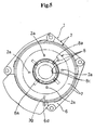
- the stator housing 2 has engagement portions 2a formed on its bottom surface, the engagement portions 2a being engaged with later described projections 8a of the rotor 8.
- the stator housing 2 includes a side housing 6 and a bottom housing 7, which are assembled to each other.
- the housing 6 has a fitting hole (not shown) and the bottom housing 7 has a fitting claw (not shown).
- the side housing 6 and the bottom housing 7 are assembled together with the fitting claw fitted into the fitting hole.
- the side housing 6 and bottom housing 7 may be formed in one piece construction as the stator housing 2.
- the engagement portions 2a may be in the form of a projection, a recess, or any shape, provided that the engagement portions 2a can engage generally rod-shaped projections 8a.
- the bottom housing 7 supports an end of the flat cable 5 and has a guide (not shown) that guides the flat cable 5 in the space defined between the stator housing and the rotor housing 3.
- the bottom housing 7 has a slide sheet 13 placed on the bottom of the space.
- the side housing 6 has a connector 6a disposed below the guide.
- the connector 6a has terminals (not shown) which are connected via the flat cable 5 to a wire harness 10 disposed on the rotor housing 3.
- the slide sheet 13 is a flat ring formed of oleoresin and allows the flat cable 5 to smoothly slide, thereby reducing the noise when the flat cable 5 slides on the bottom floor of the space.
- the side housing 6 includes a generally ring-shaped cylinder 6b and a frame 6c that is formed to surround the lower portion of the cylinder 6b.
- the cylinder 6b and frame 6c are formed in one piece construction.
- the frame 6c is formed with the connector 6a thereon, and a threaded hole therein through which the rotary connector 1 is screwed into the base of the combination switch.
- the side housing 6 and the rotor housing 3 have a mark 3g and a mark 6d, respectively, formed thereon, such that when the marks 3g and 6d face each other, they indicate that the rotary connector is at the neutral position of the wound flat cable.
- the rotor housing 3 rotatably fits to the stator housing 2 and rotates together with the steering wheel 11.
- the rotor housing 3 has claws 3d formed in its inner circumferential surface 3c, the claws 3d engaging fitting portions 4a provided in the attachment 4.
- the rotor housing 3 also has a stepped portion (not shown) that abuts upright circumferential walls 4b of the attachment 4.
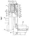
- the fitting portions 4a and upright circumferential walls 4b of the attachment 4 as shown in Figs. 3 and 4 permit the stator housing 2 to couple with the rotor housing 3.
- the attachment 4 has a flange 4c at its lower circumference. That is, the attachment 4 couples with the stator housing 2 and rotor housing 3 by using a means disclosed in for example, Japanese Patent Preliminary Publication (KOKAI) No. 10-22029.
- the flange 4c includes an annular groove 4d that receives a spring 9 therein, an annular projection 4e formed in the annular groove 4d, and a supporting frame 4f formed to surround the annular groove 4d.
- the lower end of the spring 9 is received between the annular groove 4d and the annular projection 4e such that the spring 9 is prevented from moving laterally.
- the frame 4f has a narrow ring-shaped groove 4g formed in the top surface 4h of the frame 4f.
- the top surface 4h abuts the bottom surface 2b of the stator housing 2.
- the ring groove 4g is a groove that holds a lubricant and a grease therein. The lubricant and grease are applied to the sliding surfaces of the rotating attachment 8 and the bottom housing 7.
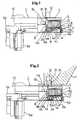
- the spring 9 is in the form of a compressed coil spring. As shown in Figs. 1 and 2, the lower end of the spring is received in the annular groove 4d and the upper end of the spring 9 is in pressure contact with the projections 8a of the rotor 8.
- the flat cable 5 includes, for example, a plurality of belt-shaped electrically conductive wires spaced apart by predetermined intervals, the wires being sandwiched by two sheets of insulating resin film heat-bonded to each other.
- the flat cable 5 has one end thereof connected to the terminals of the connector 6a of the stator housing 2 and the other end thereof connected to the wire harness 10 of the rotor housing 3.
- the flat cable 5 is accommodated in the doughnut-shaped space defined by the stator housing 2 and the rotor housing 3 such that the rotor housing 3 can be rotated through more than two rotations in each of a clockwise direction and a counterclockwise direction from the neutral position at which the vehicle runs straight.
- the rotor 8 When the steering wheel 11 has not been mounted on the rotary connector 1, the rotor 8 causes the rotor housing 3 to engage the stator housing 2, thereby preventing the rotor housing 3 from rotating.
- the rotor 8 includes a cylinder 8b and the plurality of projections 8a.
- the cylinder 8b is disposed in a hollow shaft cylinder 3f of the rotor housing 3.
- the plurality of projections 8a are provided at the lower end of the cylinder 8b and inserted into vertical grooves 4i formed in the attachment 4.
- the projections 8a include four rod-like members.
- the projections 8a may be of any number and any shape, provided that the projections 8a can support the spring 9 and engage the engagement portions 2a.
- the projections 8a may have thick base portions or ribs and may be in the shape of tooth or wedge.
- the projections 8a need not be as many as the engagement portions 2a and may differ in number from the engagement portions 2a.
- the number of projections 8a and engagement portions 2a may be increased or the shape of them may be triangular so that when the projections 8a are engaged with the engagement portions 2a, the projections 8a and engagement portions 2a are prevented from moving laterally, thus rattling can be reduced.
- the rotor 8 rotates together with the attachment 4 and the rotor housing 3.
- the rotor 8 has a pressing surface 8c formed on the upper end of the cylinder 8b, the pressing surface 8c abutting the lower surface 11a of the steering wheel 11.
- the pressing surface 8c of the rotor 8 is pressed against the lower surface 11a of the steering wheel 11 as shown in Fig. 1, so that the projections 8a is lowered while compressing the spring 9.
- the projections 8a are disengaged from the bottom surface 2b of the stator housing 2.
- the lowered projections 8a enter the annular grooves 4d as shown in Fig. 1. Due to the disengagement of the projections 8a of the rotor 8 from the stator housing 2, the rotor 8, attachment 4, and rotor housing 3 become free to rotate relative to the stator housing 2.
- the rotor 8 is rotatable together with the rotor housing 3 and the attachment 4 at all times.
- the stator housing 2 is screwed to, for example, the base of the combination switch.
- the projections 8a of the rotor 8 engage the engagement portions 2a formed on the bottom surface 2b of the stator housing 2 such that the rotary connector is locked. Therefore, the rotor 8, rotor housing 3 and attachment 4 are fixed to the stator housing 2 and do not rotate.
- the steering wheel 11 on the rotary connector 1 When the steering wheel 11 on the rotary connector 1 is disengaged from the steering shaft, for example, for the purpose of checking or maintenance of the steering wheel 11, the steering wheel that was depressing the rotor 8 is removed, so that the spring 9 pushes up the rotor 8. Then, the projections 8a are raised to engage the engagement portions 2a of the stator housing 2, thereby preventing the rotor 8, rotor housing 3, and attachment 4 from rotating.
- the rotor housing 3 may be locked in position.
- the rotary connector 1 incorporates the rotor 8 that serves as a locking mechanism.
- the projections 8a are allowed to engage the engagement portions 2a, thereby maintaining the positional relation between the projections 8a and the engagement portions 2a immediately before the steering wheel 11 has been disengaged from the vehicle.
- the rotor housing is not subjected to a large positional error. This prevents the rotary connector from being assembled at a non-neutral position of the steering wheel by mistake.
Landscapes
- Engineering & Computer Science (AREA)
- Mechanical Engineering (AREA)
- Steering Controls (AREA)
- Electric Cable Arrangement Between Relatively Moving Parts (AREA)
Claims (6)
- Connecteur rotatif (1) comprenant:un boîtier de stator (2) prévu sur une carrosserie d'une automobile,un boîtier de rotor (3) qui est assemblé de façon rotative au boîtier de stator (2) et est couplé à un volant (11),un câble plat (5) qui est reçu dans un espace défini entre le boîtier de rotor (3) et le boîtier de stator (2) en étant formé avec une partie de prise (2a) ;un rotor (8) ayant une saillie (8a), la saillie (8a) venant en prise de la partie de prise (2a) pour empêcher le boîtier de rotor (3) de tourner quand le volant (11) n'a pas été assemblé au connecteur rotatif,caractérisé en ce que le rotor (8) comprend :un cylindre (8b) inséré dans un cylindre d'axe creux (3f) du boîtier de rotor (3), la saillie (8a) étant formée sur une circonférence du cylindre (8b) ; etune surface d'application (8c) butant contre une surface inférieure (11a) du volant (11) quand le volant (11) a été assemblé au connecteur rotatif (1) de sorte que la saillie (8a) soit hors de prise de la partie de prise (2a) du boîtier de stator (2).
- Connecteur rotatif selon la revendication 1, dans lequel la saillie (8a) du rotor (8) est l'une d'une pluralité de saillies qui font saillie depuis une partie inférieure du cylindre (8b) et la partie de prise (2a) du boîtier de stator (2) est une saillie qui fait saillie à partir d'une surface inférieure (2b) du boîtier de stator (2).
- Connecteur rotatif selon la revendication 2, dans lequel le rotor (8) est assemblé à une fixation (4) qui relie conjointement le boîtier de stator (2) et le boîtier de rotor (3) de sorte que le boîtier de rotor (3) est apte à tourner par rapport au boîtier de stator (2), dans lequel la fixation (4) supporte un ressort (9) qui pousse le rotor (8).
- Connecteur rotatif selon la revendication 3, dans lequel le ressort (9) présente une extrémité supérieure en contact sous pression avec les saillies (8a) et une extrémité inférieure reçue entre une gorge annulaire (4d) formée dans la fixation (4) et une saillie (4e) formée sur un côté intérieur de la gorge annulaire (4d).
- Connecteur rotatif selon la revendication 4, dans lequel lorsque le volant (11) a été assemblé sur le connecteur rotatif (1) et que le rotor (8) est poussé vers le bas par le volant (11), les saillies (8a) du rotor (8) s'abaissent dans la gorge annulaire (4d).
- Connecteur rotatif selon la revendication 3 ou la revendication 4, dans lequel la fixation (4) présente des gorges verticales (4i) dans lesquelles les saillies (8a) du rotor (8) pénètrent de sorte que les saillies (8a) sont verticalement mobiles dans les gorges verticales (4i).
Applications Claiming Priority (2)
| Application Number | Priority Date | Filing Date | Title |
|---|---|---|---|
| JP35315699A JP2001167858A (ja) | 1999-12-13 | 1999-12-13 | 回転コネクタ装置 |
| JP35315699 | 1999-12-13 |
Publications (3)
| Publication Number | Publication Date |
|---|---|
| EP1108619A2 EP1108619A2 (fr) | 2001-06-20 |
| EP1108619A3 EP1108619A3 (fr) | 2003-10-15 |
| EP1108619B1 true EP1108619B1 (fr) | 2007-02-14 |
Family
ID=18428950
Family Applications (1)
| Application Number | Title | Priority Date | Filing Date |
|---|---|---|---|
| EP00127050A Expired - Lifetime EP1108619B1 (fr) | 1999-12-13 | 2000-12-11 | Connecteur rotatif |
Country Status (5)
| Country | Link |
|---|---|
| US (1) | US6299453B2 (fr) |
| EP (1) | EP1108619B1 (fr) |
| JP (1) | JP2001167858A (fr) |
| KR (1) | KR100662969B1 (fr) |
| DE (1) | DE60033362T2 (fr) |
Families Citing this family (7)
| Publication number | Priority date | Publication date | Assignee | Title |
|---|---|---|---|---|
| JP3522148B2 (ja) * | 1999-04-23 | 2004-04-26 | アルプス電気株式会社 | 回転コネクタ |
| US6712618B2 (en) * | 2002-01-10 | 2004-03-30 | Welch Leroy | Electrical brushless rotary connector assembly |
| US6962497B2 (en) * | 2003-04-16 | 2005-11-08 | The Furukawa Electric Co., Ltd. | Rotary connector having an identifiable neutral position |
| KR100878090B1 (ko) | 2007-10-10 | 2009-01-14 | 현대자동차주식회사 | 회전식 스위치조립체 |
| JP5259265B2 (ja) * | 2008-06-19 | 2013-08-07 | ナイルス株式会社 | 回転コネクタ装置 |
| KR101789820B1 (ko) * | 2011-04-15 | 2017-10-25 | 엘지이노텍 주식회사 | 앵글센서 |
| US10286861B2 (en) | 2015-07-02 | 2019-05-14 | Honda Motor Co., Ltd. | Cable reel |
Family Cites Families (8)
| Publication number | Priority date | Publication date | Assignee | Title |
|---|---|---|---|---|
| US4607898A (en) * | 1984-11-13 | 1986-08-26 | Sheller-Globe Corporation | Spiral flex-circuit system for steering wheels |
| JPH0183287U (fr) | 1987-11-24 | 1989-06-02 | ||
| JPH082947Y2 (ja) * | 1988-04-18 | 1996-01-29 | アルプス電気株式会社 | ケーブルリール |
| DE4446901C2 (de) * | 1993-12-27 | 2001-01-25 | Nihon Plast Co Ltd | Elektrischer Uhrfederverbinder |
| US5429517A (en) * | 1994-02-14 | 1995-07-04 | Methode Electronics, Inc. | Two-piece clockspring with lock and wire harness assembly |
| US5630723A (en) * | 1994-11-30 | 1997-05-20 | Nihon Plast Co., Ltd. | Cable type electric connector |
| FR2756108B1 (fr) * | 1996-11-20 | 1999-01-22 | Valeo Electronique | Contacteur tournant a moyens de verrouillage escamotables pour vehicule automobile |
| FR2773127B1 (fr) * | 1997-12-30 | 2000-02-04 | Valeo Electronique | Contacteur electrique tournant |
-
1999
- 1999-12-13 JP JP35315699A patent/JP2001167858A/ja active Pending
-
2000
- 2000-11-29 US US09/725,061 patent/US6299453B2/en not_active Expired - Fee Related
- 2000-12-11 EP EP00127050A patent/EP1108619B1/fr not_active Expired - Lifetime
- 2000-12-11 DE DE60033362T patent/DE60033362T2/de not_active Expired - Fee Related
- 2000-12-12 KR KR1020000075475A patent/KR100662969B1/ko not_active Expired - Fee Related
Also Published As
| Publication number | Publication date |
|---|---|
| US6299453B2 (en) | 2001-10-09 |
| KR20010062346A (ko) | 2001-07-07 |
| EP1108619A2 (fr) | 2001-06-20 |
| DE60033362D1 (de) | 2007-03-29 |
| EP1108619A3 (fr) | 2003-10-15 |
| JP2001167858A (ja) | 2001-06-22 |
| DE60033362T2 (de) | 2007-10-31 |
| KR100662969B1 (ko) | 2006-12-28 |
| US20010003683A1 (en) | 2001-06-14 |
Similar Documents
| Publication | Publication Date | Title |
|---|---|---|
| US5752843A (en) | Cable type electric connector | |
| US7703309B2 (en) | Electric steering lock device and assembling method | |
| US7823426B2 (en) | Assembling method of electric steering lock device | |
| US20120011959A1 (en) | Auto lock mechanism of clock spring for vehicle | |
| EP1108619B1 (fr) | Connecteur rotatif | |
| US20030209043A1 (en) | Electronically-driven lock | |
| US4466262A (en) | Steering lock | |
| EP0390089A2 (fr) | Dispositif de verrouillage d'un volant de direction | |
| US5884936A (en) | Steering wheel assembly with self-docking connector | |
| JPH051189B2 (fr) | ||
| GB2282574A (en) | Fitting a steering wheel with airbag to a steering column | |
| EP0926009B1 (fr) | Interrupteur de colonne de direction avec connecteur rotatif | |
| CN217518406U (zh) | 一种电气柜门锁开闭机构 | |
| US7673483B2 (en) | Anti-theft device for a motor vehicle, such as an electronic anti-theft device | |
| US5766028A (en) | Electrical connecting device between rotor and stator | |
| EP1120318B1 (fr) | Dispositif de transmission de signaux pour une direction | |
| JPH0834288A (ja) | 車両用後写鏡装置 | |
| EP1036713A2 (fr) | Connecteur rotatif capable de facilement et fiablement reverrouiller un boitier mobile en position de rotation neutre après un test de rotation | |
| US6386062B1 (en) | Fixing device for steering wheel | |
| GB2216475A (en) | Free-wheeling steering wheel for vehicle theft prevention | |
| EP4052970A1 (fr) | Ensemble goupille de verrouillage | |
| JP2001347904A (ja) | ステアリング用信号伝達装置 | |
| JPH0741114Y2 (ja) | ブラシレス伝送装置 | |
| JPH0720290Y2 (ja) | 自動車のステアリングロック取付構造 | |
| KR100820393B1 (ko) | 자동차용 스티어링 휠 및 src의 결합구조 |
Legal Events
| Date | Code | Title | Description |
|---|---|---|---|
| PUAI | Public reference made under article 153(3) epc to a published international application that has entered the european phase |
Free format text: ORIGINAL CODE: 0009012 |
|
| AK | Designated contracting states |
Kind code of ref document: A2 Designated state(s): AT BE CH CY DE DK ES FI FR GB GR IE IT LI LU MC NL PT SE TR |
|
| AX | Request for extension of the european patent |
Free format text: AL;LT;LV;MK;RO;SI |
|
| PUAL | Search report despatched |
Free format text: ORIGINAL CODE: 0009013 |
|
| AK | Designated contracting states |
Kind code of ref document: A3 Designated state(s): AT BE CH CY DE DK ES FI FR GB GR IE IT LI LU MC NL PT SE TR |
|
| AX | Request for extension of the european patent |
Extension state: AL LT LV MK RO SI |
|
| 17P | Request for examination filed |
Effective date: 20040406 |
|
| AKX | Designation fees paid |
Designated state(s): DE FR GB |
|
| GRAP | Despatch of communication of intention to grant a patent |
Free format text: ORIGINAL CODE: EPIDOSNIGR1 |
|
| GRAS | Grant fee paid |
Free format text: ORIGINAL CODE: EPIDOSNIGR3 |
|
| GRAA | (expected) grant |
Free format text: ORIGINAL CODE: 0009210 |
|
| AK | Designated contracting states |
Kind code of ref document: B1 Designated state(s): DE FR GB |
|
| REG | Reference to a national code |
Ref country code: GB Ref legal event code: FG4D |
|
| REF | Corresponds to: |
Ref document number: 60033362 Country of ref document: DE Date of ref document: 20070329 Kind code of ref document: P |
|
| ET | Fr: translation filed | ||
| PLBE | No opposition filed within time limit |
Free format text: ORIGINAL CODE: 0009261 |
|
| STAA | Information on the status of an ep patent application or granted ep patent |
Free format text: STATUS: NO OPPOSITION FILED WITHIN TIME LIMIT |
|
| 26N | No opposition filed |
Effective date: 20071115 |
|
| PGFP | Annual fee paid to national office [announced via postgrant information from national office to epo] |
Ref country code: FR Payment date: 20081216 Year of fee payment: 9 |
|
| PGFP | Annual fee paid to national office [announced via postgrant information from national office to epo] |
Ref country code: DE Payment date: 20090225 Year of fee payment: 9 |
|
| PGFP | Annual fee paid to national office [announced via postgrant information from national office to epo] |
Ref country code: GB Payment date: 20081219 Year of fee payment: 9 |
|
| GBPC | Gb: european patent ceased through non-payment of renewal fee |
Effective date: 20091211 |
|
| REG | Reference to a national code |
Ref country code: FR Ref legal event code: ST Effective date: 20100831 |
|
| PG25 | Lapsed in a contracting state [announced via postgrant information from national office to epo] |
Ref country code: FR Free format text: LAPSE BECAUSE OF NON-PAYMENT OF DUE FEES Effective date: 20091231 |
|
| PG25 | Lapsed in a contracting state [announced via postgrant information from national office to epo] |
Ref country code: DE Free format text: LAPSE BECAUSE OF NON-PAYMENT OF DUE FEES Effective date: 20100701 |
|
| PG25 | Lapsed in a contracting state [announced via postgrant information from national office to epo] |
Ref country code: GB Free format text: LAPSE BECAUSE OF NON-PAYMENT OF DUE FEES Effective date: 20091211 |