EP1108860A1 - Mecanisme de blocage pour dispositif de reglage de soupape - Google Patents
Mecanisme de blocage pour dispositif de reglage de soupape Download PDFInfo
- Publication number
- EP1108860A1 EP1108860A1 EP99973938A EP99973938A EP1108860A1 EP 1108860 A1 EP1108860 A1 EP 1108860A1 EP 99973938 A EP99973938 A EP 99973938A EP 99973938 A EP99973938 A EP 99973938A EP 1108860 A1 EP1108860 A1 EP 1108860A1
- Authority
- EP
- European Patent Office
- Prior art keywords
- rotating body
- oil pressure
- locking member
- lock mechanism
- groove
- Prior art date
- Legal status (The legal status is an assumption and is not a legal conclusion. Google has not performed a legal analysis and makes no representation as to the accuracy of the status listed.)
- Withdrawn
Links
Images



Classifications
-
- F—MECHANICAL ENGINEERING; LIGHTING; HEATING; WEAPONS; BLASTING
- F01—MACHINES OR ENGINES IN GENERAL; ENGINE PLANTS IN GENERAL; STEAM ENGINES
- F01L—CYCLICALLY OPERATING VALVES FOR MACHINES OR ENGINES
- F01L1/00—Valve-gear or valve arrangements, e.g. lift-valve gear
- F01L1/34—Valve-gear or valve arrangements, e.g. lift-valve gear characterised by the provision of means for changing the timing of the valves without changing the duration of opening and without affecting the magnitude of the valve lift
- F01L1/344—Valve-gear or valve arrangements, e.g. lift-valve gear characterised by the provision of means for changing the timing of the valves without changing the duration of opening and without affecting the magnitude of the valve lift changing the angular relationship between crankshaft and camshaft, e.g. using helicoidal gear
- F01L1/3442—Valve-gear or valve arrangements, e.g. lift-valve gear characterised by the provision of means for changing the timing of the valves without changing the duration of opening and without affecting the magnitude of the valve lift changing the angular relationship between crankshaft and camshaft, e.g. using helicoidal gear using hydraulic chambers with variable volume to transmit the rotating force
-
- F—MECHANICAL ENGINEERING; LIGHTING; HEATING; WEAPONS; BLASTING
- F01—MACHINES OR ENGINES IN GENERAL; ENGINE PLANTS IN GENERAL; STEAM ENGINES
- F01L—CYCLICALLY OPERATING VALVES FOR MACHINES OR ENGINES
- F01L1/00—Valve-gear or valve arrangements, e.g. lift-valve gear
- F01L1/34—Valve-gear or valve arrangements, e.g. lift-valve gear characterised by the provision of means for changing the timing of the valves without changing the duration of opening and without affecting the magnitude of the valve lift
- F01L1/344—Valve-gear or valve arrangements, e.g. lift-valve gear characterised by the provision of means for changing the timing of the valves without changing the duration of opening and without affecting the magnitude of the valve lift changing the angular relationship between crankshaft and camshaft, e.g. using helicoidal gear
- F01L1/3442—Valve-gear or valve arrangements, e.g. lift-valve gear characterised by the provision of means for changing the timing of the valves without changing the duration of opening and without affecting the magnitude of the valve lift changing the angular relationship between crankshaft and camshaft, e.g. using helicoidal gear using hydraulic chambers with variable volume to transmit the rotating force
- F01L2001/3445—Details relating to the hydraulic means for changing the angular relationship
- F01L2001/34453—Locking means between driving and driven members
-
- Y—GENERAL TAGGING OF NEW TECHNOLOGICAL DEVELOPMENTS; GENERAL TAGGING OF CROSS-SECTIONAL TECHNOLOGIES SPANNING OVER SEVERAL SECTIONS OF THE IPC; TECHNICAL SUBJECTS COVERED BY FORMER USPC CROSS-REFERENCE ART COLLECTIONS [XRACs] AND DIGESTS
- Y10—TECHNICAL SUBJECTS COVERED BY FORMER USPC
- Y10T—TECHNICAL SUBJECTS COVERED BY FORMER US CLASSIFICATION
- Y10T74/00—Machine element or mechanism
- Y10T74/21—Elements
- Y10T74/2101—Cams
- Y10T74/2102—Adjustable
Definitions
- the present invention relates to a lock mechanism for a valve timing regulation device which varies the opening and closing timing of one or both of an intake valve and an exhaust valve by an actuator in accordance with an operational condition of an engine.
- a lock mechanism for a valve timing regulation device which is provided with a rotor and a housing able to rotate relative to a camshaft which opens and closes a valve of an engine system.
- the rotor and housing are synchronously rotated by locking them in response to engine operating conditions and are relatively rotated by releasing the lock.
- Fig. 1 is a cross sectional view along an axial direction showing a lock mechanism for a valve timing regulation device in a first conventional example as disclosed for example in JP-A-9-280018.
- reference numeral 1 denotes a camshaft which drives the opening and closing of a valve in an engine system and 2 is a timing pulley which is rotatably attached on the camshaft 1.
- a rotational driving force is transmitted from a crank shaft (not shown) of the engine to the timing pulley 2.
- 3 is a housing which is fixed to rotate integrally with respect to the timing pulley 2.
- 4 is a rotor which is linked to a tip of the camshaft 1 and which is stored in the housing 3.
- the rotor 4 has a plurality of vanes 4a which extend in a radial direction and slidably abut with a side of the timing pulley 2 and an inner peripheral surface of the housing 3.
- the rotor 4 can rotate relatively to the housing 3.
- 5 is a cover which covers the open end of the housing 3.
- 6 is a through hole which is provided on one vane 4a of the rotor 4 and which extends in an axial direction of the camshaft 1.
- 7 is a locking hole which is provided on the timing pulley 2 and which is communicated with the through hole 6.
- 8 is a lock pin which is slidably inserted in the through hole. The lock pin 8 is urged by a spring 9 and is inserted into the locking hole 7.
- 10a is an oil passage which is connected to the locking hole 7
- 10b is an oil passage which is connected to the large diameter hole 6a of the through hole 6.
- the oil passages 10a, 10b are connected to an oil pressure supply means (oil pump) through an oil control valve (not shown).
- the first conventional lock mechanism for a valve timing regulation device Since the first conventional lock mechanism for a valve timing regulation device is constructed above, it is necessary to store a locking pin 8 in the vane 4a (through hole 6) of the rotor 4 to slide along the axial direction of the camshaft 1.
- the vane 4a storing the locking pin 8 must be formed to be longer in the circumferential direction in comparison with other vanes which do not store the locking pin 8.
- the length in the circumferential direction is lengthened, not only is the regulated angular range of the valve timing regulation device reduced, but also the balance with respect to the center of rotation of the rotor 4 is lost. Thus, problems with respect to mechanical strength and the generation of vibrations have arisen.
- Fig. 2 is a cross sectional view in the radial direction of a lock mechanism for a valve timing regulation device according to a second conventional example as disclosed for example in JP-A-9-303118.
- Those components which are the same or similar to components in Fig. 1 are denoted by the same reference numerals and further discussion will be omitted.
- reference numerals 3a, 3b are shoes which protrude from the inner peripheral surface of the housing 3. Of the shoes 3a, 3b, one shoe 3a is formed to be longer in the circumferential direction than the other shoe 3b in order to store the lock mechanism.
- 11 is a pin hole which is provided on the shoe 3a and extends in a radial direction of the housing 3.
- the locking pin 12 on the housing 3 side is inserted into the locking hole 14 of the rotor 4 by the urging force of the spring 13, the housing 3 and the rotor 4 are locked to rotate synchronously.
- the oil pressure supplied to the oil passage 15 in response to an operational condition of the engine exceeds a predetermined value
- the locking pin 12 is displaced towards an outer peripheral surface of the housing 3 by the oil pressure against the urging force of the spring 13 and the locking pin 12 retracts from the locking hole 14.
- the locking of the rotor 4 and the housing 3 is released and both components are retained in a state allowing relative rotation.
- the second conventional lock mechanism for a valve timing regulation device is constructed above, of the shoes 3a, 3b of the housing 3, it is required to make the shoe 3a which acts as storage for the lock mechanism to be longer in the circumferential direction than the other shoe 3b.
- the length in the circumferential direction is lengthened, in the same way as the first conventional example, not only is the regulated angular range of the valve timing regulation device reduced, but also the balance with respect to the center of rotation of the rotor 4 is lost. Thus, problems with respect to mechanical strength and the generation of vibrations have arisen.
- the present invention is proposed to solve the above problems and has the object of providing a lock mechanism for a valve timing regulation device in which a plurality of shoes provided on the housing and a plurality of vanes provided on the rotor have approximately the same length in the circumferential direction.
- the lock mechanism of the present invention enables the enlargement of the angular range to be regulated by the valve timing regulation device and allows great reductions in the degree of unbalance with respect to the rotational center. Furthermore, problems with respect to mechanical strength and the generation of vibrations are avoided.
- the present invention has the further object of providing a lock mechanism for a valve timing regulation device which can accurately and smoothly perform locking and unlocking operations.
- the present invention has the further object of providing a lock mechanism for a valve timing regulation device which can improve productivity by the ease molding by sintering or the like and which thus enables reduction in manufacturing costs.
- the present invention has the further object of providing a lock mechanism for a valve timing regulation device which enables improvement of the operation of the locking member.
- the present invention has the further object of providing a lock mechanism for a valve timing regulation device which enables the application of an oil pressure to a locking member in both an advancing and retarding direction of the rotating body and which can retain or release normal locking when the oil pressure is not less than a predetermined value.
- the present invention has the further object of providing a lock mechanism for a valve timing regulation device in which a function of mounting it on one of the first and second rotating bodies and a function of slidable engagement with the other of the first and second rotating bodies can be achieved by a single component.
- the present invention has the further object of providing a lock mechanism for a valve timing regulation device which can improve mass production efficiency by the simplification of component structure.
- a lock mechanism for a valve timing regulation device which performs locking to enable synchronous rotation of a first rotating body and a second rotating body and releases the locking to enable relative rotation of the first rotating body and the second rotating body, the first and second rotating bodies being provided on a rotation shaft for opening and dosing engine valves
- the lock mechanism comprising: an engaging projection disposed on an axial end face of one of the first rotating body and the second rotating body; a radial groove disposed on an axial end face of the other of the first rotating body and the second rotating body which faces the one of the first rotating body and the second rotating body, the radial groove extending in a radial direction of the rotating body; a circumferential groove extending in a circumferential direction of the rotating body from the radial groove, the circumferential groove being engaged with the engaging projection to allowing sliding of the engaging projection; a locking member which is stored in the radial groove to slide in the radial direction of the rotating body; a guide groove formed on the locking member
- This type of lock mechanism for a valve timing regulation device has an engaging projection provided on an axial end face of one of the first and second rotating bodies, a radial groove provided on an axial end face of the other of the first and second rotating bodies, and a locking member slidably inserted in the radial groove. Therefore, the formation region of the radial groove on the rotating body can be formed with sufficient mechanical strength by the locking member which is fit into the radial groove. As a result, it is not necessary to lengthen the shoe or the vane storing the locking member so as to be longer in the circumferential direction than other vanes or shoes not storing the locking member. Thus, it is possible to form each vane or each shoe with approximately the same length in the circumferential direction.
- the angular range regulated by the valve timing regulation device can be-enlarged and it is possible to eliminate the problems such as mechanical strength and the generation of vibration by large reductions in the degree of unbalance with respect to the rotational center of the rotating body.
- the oil pressure of the oil pressure control system provided in the valve timing regulation device is not more than a predetermined value
- the first rotating body and the second rotating body can be rotated synchronously by the locking member locking the engaging projection by the urging means.
- the oil pressure of the oil pressure control system becomes more than the predetermined value
- the locking of the engaging projection by the locking member is released by the displacement of the locking member due to the oil pressure resisting the urging means and thus the first and second rotating bodies can rotate relatively to one another. Therefore, it is possible to accurately and smoothly perform both synchronous and relative rotations of the first and second rotating bodies in response to the variation in the oil pressure of the oil pressure control system.
- the circumferential groove may be adapted to extend in a circumferential direction of the rotating body from both sides of the radial groove and to be divided circumferentially by the radial groove.
- the groove width of the guide groove gradually increases towards one of the divided circumferential grooves.
- the lock mechanism for a valve timing regulation device such as the above allows the rapid introduction of the engaging projection, which is not aligned with the guide groove, into the guide groove of the locking member at a time when the locking member is slightly displaced by the oil pressure in a direction which resists the urging means.
- the locking member is displaced in the direction resisting the urging means, it is possible to improve the response characteristics of the engaging projection which is not aligned with the guide groove.
- an oil pressure which can resist the urging force of the urging means may be reduced below the predetermined value.
- the second rotating body tends to displace in a retarding direction by the reaction torque of the camshaft, the engaging projection slides on the side wall of the guide groove.
- the engaging projection displaces the locking member mechanically in a radial direction towards an outer periphery of the rotating body against the urging force of the urging means. Therefore, even when no oil pressure exists, the locking member can be surely retained in a lock released state up to a position of maximum retardation of the second rotating body.
- the locking member may be formed to be rectangular in cross section, and the radial groove storing the locking member may be formed with a cross sectional shape which is adjusted so that the locking member can slide therein.
- the lock mechanism for the valve timing regulation device such as the above, it is possible to increase ease of manufacture of dies for molding and die formation of the locking member by sintering metal or the like, productivity can be improved, and costs can be reduced.
- a plate covering the radial groove and the circumferential groove may be interposed between the first rotating body and the second rotating body.
- the lock mechanism for the valve timing regulation device since the circumferential groove and the exposed surface of the locking member inserted into the radial groove are covered by the plate, it is possible to prevent the advancing/retarding oil chamber provided in the valve timing regulation device from being communicated with the radial groove and the circumferential groove. Furthermore, the sliding of the locking member is improved.
- the plate may be provided with a common oil pressure passage which communicates with each of an advancing oil pressure chamber and a retarding oil pressure chamber, the oil pressure passage may be provided with an oil passage switching valve for switching an oil pressure applying passage to the locking member between the advancing oil pressure chamber and the retarding oil pressure chamber.
- This type of lock mechanism for the valve timing regulation device allows selective application of an oil pressure to the locking member from either the advancing oil pressure chamber or the retarding oil pressure chamber. Thus, it is possible to maintain a lock released state of the first rotating body and the second rotating body as long as the applied oil pressure is not less than a predetermined value.
- engaging projections may be provided on both surfaces of the plate.
- the engaging projection on one face of the plate engages with the guide groove and the circumferential groove.
- the engaging projection on the other face of the plate is fitted into an engagement hole provided in the rotating body which does not have the radial groove and the circumferential groove.
- the plate is adapted to rotate together with the rotating body and to rotate relatively to the other rotating body.
- the engaging projection other than that engaged with the guide groove and the circumferential groove is engaged with the engagement hole of the rotating body.
- the engaging projections may be formed by a single engaging member which passes through the plate.
- Fig. 1 is a cross sectional view in the axial direction of a lock mechanism for a valve timing regulation device according to a first conventional example.
- Fig. 2 is a cross sectional view in the radial direction of a lock mechanism for a valve timing regulation device according to a second conventional example.
- Fig. 3 is a cross sectional view in the radial direction of a lock mechanism for a valve timing regulation device according to a first embodiment of the present invention.
- Fig. 4 is a cross sectional view along the line A-A in Fig. 3.
- Fig. 5 is an exploded perspective view of a lock mechanism for a valve timing regulation device according to the first embodiment of the present invention.
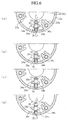
- Fig. 6(a) to Fig. 6(d) are explanatory views describing the operation of the present invention.
- Fig. 7 is a cross sectional view of a lock mechanism for a valve timing regulation device according to a second embodiment of the present invention.
- Fig. 8 is a plan view showing a plate of a valve timing regulation device according to a third embodiment of the present invention.
- Fig. 3 is a cross sectional view in the radial direction of a lock mechanism for a valve timing regulating device according to a first embodiment of the present invention.
- Fig. 4 is a cross sectional view along the line A-A in Fig. 3.
- reference numeral 21 denotes a first rotating body which is provided on a camshaft for driving the opening and closing of the valves of an engine.
- the first rotating body 21 includes a first housing 22 rotatably mounted on the camshaft and a second housing 23 fixed to the first housing 22.
- the second rotating body 24 is a second rotating body (rotor) which is linked to the camshaft and stored in the second housing 23.
- the second rotating body 24 is comprised by a rotor which can rotate relatively to the first rotating body 21.
- 23a denotes a plurality of shoes which are disposed at fixed intervals on the inner peripheral surface of the second housing 23 so as to protrude from the inner peripheral surface of the second housing 23.
- the tips of the shoes 23a slidably abut with a body portion of the second rotating body 24.
- 24a denotes a plurality of vanes which are arranged on the body portion of the second rotating body 24 and extend in a radial direction from the body portion of the second rotating body 24.
- the tips of the vanes 24a slidably abut with the inner peripheral surface of the second housing 23.
- 25 is an advancing oil pressure chamber which rotates each vane 24a in an advancing direction.
- 26 is an retarding oil pressure chamber which rotates each vane 24a in a retarding direction.
- the advancing oil pressure chamber 25 and the retarding oil pressure chamber 26 are formed in a fan shape between each shoe 23a and each vane 24a and between the second housing 23 and the second rotating body 24.
- a lock mechanism which locks the first rotating body 21 and the second rotating body 24 to enable synchronous rotation of the first rotating body 21 and the second rotating body 24 and which allows relative rotation of the first rotating body 21 and the second rotating body 24 by releasing the lock.
- Fig. 5 is an exploded perspective view of a lock mechanism for a valve timing regulation device according to the first embodiment of the present invention.
- the lock mechanism as shown in Fig. 5 is shown from a vertical direction opposite to the lock mechanism 30 as shown in Fig. 3 and Fig. 4 but has the same structure.
- 31 denotes a concave portion which is formed on an end face in an axial direction of the second housing 23 and which opens towards an end face in the axial direction of the second rotating body 24.
- 32 is a radial groove for storage of the locking member which is formed on the bottom face of the concave portion 31 and extends in a radial direction of the housing 23.
- 33a is a drain hole which communicates with the radial groove 32 and opens on an outer peripheral surface of the housing 23.
- 34a, 34b are circumferential grooves which branch from both sides of the radial groove 32 and extend in a circumferential direction of the housing 23.
- the circumferential grooves 34a, 34b are separated longitudinally by the radial groove 32.
- One circumferential groove 34a extends in an advancing direction and the other circumferential groove 34b extends in a retarding direction.
- 35 is a locking member which is fitted into the radial groove 32. The locking member 35 can slide in the radial direction of the first rotating body 21 within the radial groove 32.
- the locking member 35 has a quadrangular cross section, and the radial groove 32 which stores the locking member 35 has a cross section (squared groove shape) adapted to the locking member 35.
- 35a is a guide groove which is formed in approximately a central section of the locking member 35.
- the guide groove 35a can communicate mutually with the circumferential grooves 34a, 34b.
- the lock engaging projection 38a (discussed below) can be guided in a direction from one circumferential groove 34a to the other circumferential groove 34b or in the opposite direction.
- the guide groove 35a is formed to gradually enlarge towards one of the circumferential grooves 34a. In this way, the displacement of the lock engaging projection 38a from the one of the circumferential grooves 34a is facilitated.
- 35b is a pressure receiving portion having a concave shape, which is provided on an end portion of the first rotating body 21 towards a rotational center in the locking member 35.
- 36 is a spring acting as an urging means which urges the locking member 35 towards the rotational center of the first rotational body 21.
- the guide groove 35a of the locking member 35 does not align with the circumferential groove 34a, 34b so that the lock engaging projection 38a can not pass through the guide groove 35a.
- the plate 37 is a plate which is fitted into the concave portion 31 of the second housing 23.
- the plate 37 covers the guide groove 35a of the locking member 35, the circumferential groove 34a, 34b and the radial groove 32.
- 38 is an engaging projection which is provided on the plate 37.
- the engaging projection 38 is composed of a single engaging member (for example a single pin member) which is fixed through the plate 37.
- the engaging projection 38 has a lock engaging projection portion 38a which projects from one side of the plate 37 towards the second housing 23 and a mounting engaging projection portion 38b which projects towards the second rotating body 24 from the other side of the plate 37 in order to fix the plate 37 to the second rotating body 24.
- the lock engaging projection portion 38a is attached to slide with respect to the circumferential grooves 34a, 34b and the guide groove 35a and is locked by the locking member 35.
- the 39 is an oil pressure passage which is provided in the plate 37.
- the oil pressure passage 39 acts as an oil pressure supply means for supplying an oil pressure to the pressure receiving portion 35b of the locking member 35.
- the oil pressure passage 39 has an advancing chamber communication passage 39a which communicates with the advancing oil pressure chamber 25 and an retarding chamber communication passage 39b which communicates with the retarding oil pressure chamber 26.
- 40 is an oil passage switching valve which is provided in the oil pressure passage 39. The oil passage switching valve 40 selectively switches an oil pressure applying passage for applying an oil pressure to the pressure receiving portion 35b of the locking member 35 between either the advancing chamber communication passage 39a or the retarding chamber communication passage 39b.
- 41 is an engaging protrusion which is integrated with the plate 37 and is disposed at a position apart from the mounting engaging projection portion 38b.
- 42 is an engaging concave portion which is provided on a vane 24a of the second rotating body 24 so as to face with the engaging protrusion 41.
- 43 is an engagement hole which is provided on the vane 24a so as to face with the mounting engaging projection portion 38b.
- the mounting engaging projection portion 38b is fitted in the engagement hole 43 and the plate 37 is mounted and fixed to the axial direction end face of the second rotating body 24 by the engagement of the engaging protrusion 41 and the engaging concave portion 42.
- the plate 37 is inserted into the concave portion 31 of the housing 23 in this state.
- the plate 37 inserted into the concave portion 31 can be displaced in the circumferential direction of the housing 23 by a fixed distance. That is to say, when the plate 37 is inserted into the concave portion 31, a gap with a distance of a is generated between the wall face in the circumferential direction of the concave portion 31 and the end face in the circumferential direction of the plate 37 as shown by the broken line in Fig. 5.
- the plate can be displaced in the circumferential direction within the concave portion 31 by the distance a.
- 33 is an oil pressure supply hole which is provided in an inner peripheral portion of the housing 22.
- the oil pressure supply hole 33 is connected to the radial groove 32 on the opposite side of the drain hole 33a and acts as an oil pressure supply means which applies the oil pressure to the locking member 35 in a direction resisting the urging force of the spring 36.
- the oil pressure supply hole 33 is selectively connected with the advancing oil pressure chamber 25 and the retarding oil pressure chamber 26 through the oil pressure passage 39 of the plate 37 by the oil passage switching valve 40.
- the locking member 35 When the oil pressure applied to the locking member 35 from the oil pressure supply hole 33 is not more than a predetermined value, the locking member 35 is maintained by the urging force of the spring 36 in a position obstructing the communication between the right and left circumferential grooves 34a, 34b.
- the lock engaging projection portion 38a when the lock engaging projection portion 38a is positioned in the circumferential groove 34b situated on an retarding side, namely, in a maximum retarding position, the lock engaging projection portion 38a is maintained in a locked position by the locking member 35 as shown in Fig. 3 and the first and second rotating bodies 21, 24 rotate synchronously.
- the locking member 35 When the oil pressure becomes more than the predetermined value, the locking member 35 is displaced by the oil pressure in the radial direction towards an outer periphery of the rotating body against the urging force of the spring 36, the guide groove 35a of the locking member 35 communicates with the circumferential grooves 34a, 34b (refer to Fig. 6(a)). In this way, the lock of the lock engaging projection portion 38a is released by the locking member 35, the first and second rotating bodies 21, 24 can rotate relatively to each other.
- the lock engaging projection portion 38a displaces, together with the second rotating body 24, from the retarding side circumferential groove 34b to the advancing side circumferential groove 34a through the guide groove 35a of the locking member 35 (refer to Fig. 6 (b), (c)). Then, the lock engaging projection portion 38a abuts with the end portion of the circumferential groove 34a, the second rotating body 24 is maintained in a maximum advanced position (refer to Fig. 6(d)).
- the oil pressure supply hole 33 is connected with the advancing chamber communication passage 39a by the oil passage switching valve 40 and an oil pressure is applied to the locking member 35 from the advancing oil pressure chamber 25.
- the locking member 35 When the lock engaging projection portion 38a separates from the guide groove 35a of the locking member 35 and is positioned in the circumferential groove 34a, the locking member 35 is retained in a balanced state by the oil pressure applied to its tip and the urging force of the spring 36. Normally, in this state, an oil pressure in the advancing oil pressure chamber 25 or the retarding oil pressure chamber 26 is applied as a lock releasing oil pressure. However, when the applied oil pressure is abnormally reduced or the engine is stopped, the possibility arises that the oil pressure may be reduced to zero. In such a state, it is required to return it quickly to the maximum retarding position and to lock the first and second rotating bodies 21, 24.
- the locking member 35 is displaced in the radial direction towards a center of the rotating body by the urging force of the spring 36, the movement of the engaging projection portion 38a is restricted by the side wall of the locking member 35, and the relative rotation of the first and the second rotating body 21, 24 is restricted.
- a radial groove 32 is provided on an axial end face of the first rotating body 21, and a locking member 35 is inserted in the radial groove 32 so as to slide therein.
- a locking member 35 is inserted in the radial groove 32 so as to slide therein.
- each shoes 23 of the first rotating body 21 (second housing 23) can be formed with approximately the same length in a circumferential direction thereof and it is possible to expand the angular range to be regulated by the valve timing regulation device. Further, it is possible to greatly reduce the degree of unbalance with respect to the rotation center of the first rotating body 21 and thus solve problems such as the mechanical strength and the generation of vibration.
- a circumferential groove 34a, 34b extends in a circumferential direction of the housing 22 from both sides of the radial groove 32, namely, the circumferential groove 34a, 34b is divided in the longitudinal direction by the radial groove 32, and the groove width of the guide groove 35a gradually increases towards one of the divided circumferential grooves 34a.
- the lock engaging projection portion 38a which is displaced in the expanding direction of the groove width of the guide groove 35a can quickly be introduced into the guide groove 35a when the locking member 35 is slightly displaced by the oil pressure against the urging force of the spring 36.
- the advantage is obtained that the response characteristics of the lock engaging projection portion 38a following the displacement of the locking member 35 in a direction resisting the spring 36 are improved. Furthermore, since the locking member 35 has a quadrangular shape in cross section and the radial groove 32 storing the locking member 35 has a cross section adapted to allow sliding of the locking member 35, it is possible to easily mold the locking member by sintered metal or the like, thereby improving a mass production efficiency. In addition, since the manufacture of die for molding is also simplified, the cost can be reduced.
- a plate 37 is interposed between the first and second rotating bodies 21, 24 so as to cover the circumferential grooves 34a, 34b and the radial groove 32, the circumferential grooves 34a, 34b and the exposed surface of the locking member 35 inserted into the radial groove 32 are covered with the plate 37.
- the communication of the circumferential grooves 34a, 34b and the radial groove 32 with the advancing oil pressure chamber 25 and the retarding oil pressure chamber 26 can be prevented and it is possible to improve the sliding characteristics of the locking member 35.
- a common oil pressure passage 39 which communicates with each of the advancing oil pressure chamber 25 and the retarding oil pressure chamber 26 is provided in the plate 37, an oil passage switching valve 40 which switches the oil pressure applying passage to the locking member 35 between either the advancing oil pressure chamber 25 and the retarding oil pressure chamber 26 is provided in the oil pressure passage 39.
- an engaging projection portion 38 is provided on both surfaces of the plate and one of the engaging projections 38a can engage with the guide groove 35a and the circumferential grooves 34a, 34b.
- the mounting engaging projection portion 38b on the opposite side of the plate 37 is engaged and fixed to the engaging hole 43 provided on the second rotating body 24, and the engaging protrusion 41 of the plate 37 is engaged with the engaging concave portion 42 of the second rotating body 24.
- the engagement of the engaging hole 43 with the mounting engaging projection 38b and the engagement of the engaging concave portion 42 with the engaging protrusion 41 allow sufficient strength when assembled.
- the engaging projections 38 are formed by a single engaging member which passes through the plate 37.
- the lock engaging projection 38a projecting from one face of the plate 37 is used for locking, and the mounting engaging projection 38b projecting from the opposite face of the plate 37 is engaged with the engagement hole 43.
- the structure of the unit including the engaging projections and the plate is simplified by the reduction in number of components, costs can be reduced, and mass production efficiency can be improved.
- Fig. 7 is a cross sectional view of a lock mechanism for a valve timing regulation device according to a second embodiment of the present invention.
- a plate 37 is inserted into a concave portion 31 which is formed partially on an end face in an axial direction of the first housing 22 of the first rotating body 21.
- the plate 37 is composed of an annular plate which is co-axial with the housing 22, the plate 37 is adapted to rotate in an integrated manner with the second rotating body 24 which slides on the end face in an axial direction of the housing 22 in the circumferential direction.
- Fig. 8 is a plan view of a plate of a valve timing regulation device according to a third embodiment of the present invention.
- 37a denotes a circumferential slit provided in the annular plate 37
- the lock engaging projection 38a is slidably inserted into the circumferential slit.
- 37b denotes a plurality of through holes for bolts provided in the plate 37.
- the plate 37 is fixed to the housing 22 shown in Fig.7 by bolts (not shown) through these through holes 37b. That is to say, in the above second embodiment, the annular plate 37 is adapted to rotate together with the second rotating body 24.
- the annular plate 37 is disposed between the housing 22 of the first rotating body 21 and the second rotating body (rotor) 24 as shown in Fig. 7 and is adapted to rotate together with the housing 22.
- the lock engaging projection 38a is integrated with the second rotating body 24 and a slit 37a is provided on the plate 37 for inserting the lock engaging projection 38a so as to slide in the circumferential direction of the plate 37.
- a lock mechanism 30 is assembled with the first rotating body 21.
- the same advantage can be obtained by assembling the lock mechanism 30 with the second rotating body 24.
- a lock mechanism for a valve timing regulation device it is possible to assemble a locking member onto an end face in an axial direction other than that of a vane or a shoe in either a first rotating body or a second rotating body.
- each vane or each shoe can be formed with approximately the same circumferential length.
Landscapes
- Engineering & Computer Science (AREA)
- Mechanical Engineering (AREA)
- General Engineering & Computer Science (AREA)
- Valve Device For Special Equipments (AREA)
Applications Claiming Priority (1)
| Application Number | Priority Date | Filing Date | Title |
|---|---|---|---|
| PCT/JP1999/003431 WO2001000967A1 (fr) | 1999-06-25 | 1999-06-25 | Mécanisme de blocage pour dispositif de réglage de soupape |
Publications (2)
| Publication Number | Publication Date |
|---|---|
| EP1108860A1 true EP1108860A1 (fr) | 2001-06-20 |
| EP1108860A4 EP1108860A4 (fr) | 2007-01-17 |
Family
ID=14236077
Family Applications (1)
| Application Number | Title | Priority Date | Filing Date |
|---|---|---|---|
| EP99973938A Withdrawn EP1108860A4 (fr) | 1999-06-25 | 1999-06-25 | Mecanisme de blocage pour dispositif de reglage de soupape |
Country Status (3)
| Country | Link |
|---|---|
| US (1) | US6311657B2 (fr) |
| EP (1) | EP1108860A4 (fr) |
| WO (1) | WO2001000967A1 (fr) |
Cited By (2)
| Publication number | Priority date | Publication date | Assignee | Title |
|---|---|---|---|---|
| EP1544420A3 (fr) * | 2003-12-16 | 2008-08-27 | Schaeffler KG | Moteur à combustion interne muni d'un déphaseur hydraulique d'arbre à cames |
| DE19959187B4 (de) * | 1999-12-08 | 2008-12-11 | Schaeffler Kg | Vorrichtung zur Ver- und Entriegelung eines Rotationskolbenverstellers |
Families Citing this family (6)
| Publication number | Priority date | Publication date | Assignee | Title |
|---|---|---|---|---|
| JP2003020964A (ja) * | 2001-07-04 | 2003-01-24 | Sanshin Ind Co Ltd | 船外機用4サイクルエンジンのバルブタイミング制御装置 |
| JP2005155541A (ja) * | 2003-11-27 | 2005-06-16 | Mitsubishi Electric Corp | バルブタイミング調整装置およびその組立装置 |
| DE102004050236A1 (de) * | 2004-10-15 | 2006-05-11 | Daimlerchrysler Ag | Hydraulischer Nockenwellenversteller für eine Nockenwelle einer Brennkraftmaschine |
| DE102005014055A1 (de) * | 2005-03-23 | 2006-09-28 | Degussa Ag | Unsymmetrisch substituierte Phospholankatalysatoren |
| DE102006020314A1 (de) * | 2006-05-03 | 2007-11-08 | Schaeffler Kg | Verriegelungselement für Nockenwellenversteller |
| JP5615114B2 (ja) * | 2010-09-22 | 2014-10-29 | 株式会社ミクニ | バルブタイミング変更装置 |
Family Cites Families (8)
| Publication number | Priority date | Publication date | Assignee | Title |
|---|---|---|---|---|
| JP3066872B2 (ja) | 1990-08-28 | 2000-07-17 | スカラ株式会社 | 拡大観察装置 |
| JPH04107415U (ja) * | 1991-02-27 | 1992-09-17 | 株式会社アツギユニシア | 内燃機関のバルブタイミング制御装置 |
| JP3058080B2 (ja) | 1996-04-12 | 2000-07-04 | トヨタ自動車株式会社 | 内燃機関のバルブタイミング変更装置 |
| JP3744594B2 (ja) | 1996-05-15 | 2006-02-15 | アイシン精機株式会社 | 弁開閉時期制御装置 |
| US5979380A (en) * | 1996-07-23 | 1999-11-09 | Aisin Seiki Kabushiki Kaisha | Valve timing control device |
| DE19755495A1 (de) * | 1997-12-13 | 1999-06-17 | Schaeffler Waelzlager Ohg | Verriegelungseinrichtung für eine Vorrichtung zum Verändern der Steuerzeiten von Gaswechselventilen einer Brennkraftmaschine |
| DE19756015A1 (de) * | 1997-12-17 | 1999-06-24 | Porsche Ag | Vorrichtung zur hydraulischen Drehwinkelverstellung einer Welle zu einem Antriebsrad |
| JP3815014B2 (ja) * | 1997-12-24 | 2006-08-30 | アイシン精機株式会社 | 弁開閉時期制御装置 |
-
1999
- 1999-06-25 WO PCT/JP1999/003431 patent/WO2001000967A1/fr not_active Ceased
- 1999-06-25 EP EP99973938A patent/EP1108860A4/fr not_active Withdrawn
-
2001
- 2001-02-26 US US09/791,870 patent/US6311657B2/en not_active Expired - Fee Related
Cited By (2)
| Publication number | Priority date | Publication date | Assignee | Title |
|---|---|---|---|---|
| DE19959187B4 (de) * | 1999-12-08 | 2008-12-11 | Schaeffler Kg | Vorrichtung zur Ver- und Entriegelung eines Rotationskolbenverstellers |
| EP1544420A3 (fr) * | 2003-12-16 | 2008-08-27 | Schaeffler KG | Moteur à combustion interne muni d'un déphaseur hydraulique d'arbre à cames |
Also Published As
| Publication number | Publication date |
|---|---|
| US6311657B2 (en) | 2001-11-06 |
| EP1108860A4 (fr) | 2007-01-17 |
| WO2001000967A1 (fr) | 2001-01-04 |
| US20010011534A1 (en) | 2001-08-09 |
Similar Documents
| Publication | Publication Date | Title |
|---|---|---|
| EP1008729B1 (fr) | Actionneur hydraulique à ailettes | |
| US6276322B1 (en) | Valve timing regulation device | |
| JP5360511B2 (ja) | 弁開閉時期制御装置 | |
| JP3964207B2 (ja) | バルブタイミング調整装置 | |
| US6311657B2 (en) | Lock mechanism for valve timing regulation device | |
| US20050205032A1 (en) | Locking device for a camshaft adjuster | |
| JPH11101107A (ja) | 弁開閉時期制御装置 | |
| US20120167846A1 (en) | Valve timing regulator | |
| US20050109300A1 (en) | Valve timing adjusting device | |
| US6595173B2 (en) | Variable valve timing controller | |
| EP2434111B1 (fr) | Dispositif de changement de temporisation de soupape | |
| CN106939806B (zh) | 阀开闭定时控制装置 | |
| JP4290754B2 (ja) | バルブタイミング調整装置 | |
| JP4065080B2 (ja) | バルブタイミング調整装置及びアクチュエータ | |
| US6439183B1 (en) | Valve timing adjusting device | |
| JP4327047B2 (ja) | バルブタイミング調整装置 | |
| US4986741A (en) | Vane compressor with ball valve located at the end of vane biasing conduit | |
| JPH11311109A (ja) | 弁開閉時期制御装置 | |
| US20060260577A1 (en) | Valve timing control apparatus and internal combustion engine | |
| JPWO2001000967A1 (ja) | バルブタイミング調整装置のロック機構 | |
| JP6533322B2 (ja) | 内燃機関のバルブタイミング制御装置 | |
| JPH112108A (ja) | 内燃機関の可変バルブタイミング機構 | |
| JP2001317314A (ja) | 弁開閉時期制御装置 | |
| JP6786021B2 (ja) | バルブタイミング調整装置 | |
| JP4320903B2 (ja) | 弁開閉時期制御装置 |
Legal Events
| Date | Code | Title | Description |
|---|---|---|---|
| PUAI | Public reference made under article 153(3) epc to a published international application that has entered the european phase |
Free format text: ORIGINAL CODE: 0009012 |
|
| 17P | Request for examination filed |
Effective date: 20010220 |
|
| AK | Designated contracting states |
Kind code of ref document: A1 Designated state(s): DE |
|
| RAP1 | Party data changed (applicant data changed or rights of an application transferred) |
Owner name: MITSUBISHI DENKI KABUSHIKI KAISHA |
|
| A4 | Supplementary search report drawn up and despatched |
Effective date: 20061215 |
|
| RIC1 | Information provided on ipc code assigned before grant |
Ipc: F01L 1/344 20060101AFI20061211BHEP |
|
| STAA | Information on the status of an ep patent application or granted ep patent |
Free format text: STATUS: THE APPLICATION HAS BEEN WITHDRAWN |
|
| 18W | Application withdrawn |
Effective date: 20070129 |