EP1108914A2 - Embrayage à roue libre à crochets - Google Patents
Embrayage à roue libre à crochets Download PDFInfo
- Publication number
- EP1108914A2 EP1108914A2 EP01200306A EP01200306A EP1108914A2 EP 1108914 A2 EP1108914 A2 EP 1108914A2 EP 01200306 A EP01200306 A EP 01200306A EP 01200306 A EP01200306 A EP 01200306A EP 1108914 A2 EP1108914 A2 EP 1108914A2
- Authority
- EP
- European Patent Office
- Prior art keywords
- members
- pawl
- clutch assembly
- pockets
- notches
- Prior art date
- Legal status (The legal status is an assumption and is not a legal conclusion. Google has not performed a legal analysis and makes no representation as to the accuracy of the status listed.)
- Granted
Links
- 230000014759 maintenance of location Effects 0.000 claims 2
- 230000007246 mechanism Effects 0.000 description 16
- 230000000712 assembly Effects 0.000 description 14
- 238000000429 assembly Methods 0.000 description 14
- 239000000463 material Substances 0.000 description 9
- 230000033001 locomotion Effects 0.000 description 8
- 238000005461 lubrication Methods 0.000 description 5
- 230000005540 biological transmission Effects 0.000 description 4
- 229910000831 Steel Inorganic materials 0.000 description 3
- 238000004519 manufacturing process Methods 0.000 description 3
- 239000004033 plastic Substances 0.000 description 3
- 239000010959 steel Substances 0.000 description 3
- 238000002347 injection Methods 0.000 description 2
- 239000007924 injection Substances 0.000 description 2
- 239000002991 molded plastic Substances 0.000 description 2
- 238000003466 welding Methods 0.000 description 2
- 229910000760 Hardened steel Inorganic materials 0.000 description 1
- 230000002411 adverse Effects 0.000 description 1
- 229910052782 aluminium Inorganic materials 0.000 description 1
- XAGFODPZIPBFFR-UHFFFAOYSA-N aluminium Chemical compound [Al] XAGFODPZIPBFFR-UHFFFAOYSA-N 0.000 description 1
- 238000005452 bending Methods 0.000 description 1
- 230000000694 effects Effects 0.000 description 1
- 230000008030 elimination Effects 0.000 description 1
- 238000003379 elimination reaction Methods 0.000 description 1
- 230000013011 mating Effects 0.000 description 1
- 239000007769 metal material Substances 0.000 description 1
- 238000000034 method Methods 0.000 description 1
- 230000003014 reinforcing effect Effects 0.000 description 1
- 230000000717 retained effect Effects 0.000 description 1
Images


Classifications
-
- F—MECHANICAL ENGINEERING; LIGHTING; HEATING; WEAPONS; BLASTING
- F16—ENGINEERING ELEMENTS AND UNITS; GENERAL MEASURES FOR PRODUCING AND MAINTAINING EFFECTIVE FUNCTIONING OF MACHINES OR INSTALLATIONS; THERMAL INSULATION IN GENERAL
- F16D—COUPLINGS FOR TRANSMITTING ROTATION; CLUTCHES; BRAKES
- F16D41/00—Freewheels or freewheel clutches
- F16D41/12—Freewheels or freewheel clutches with hinged pawl co-operating with teeth, cogs, or the like
-
- F—MECHANICAL ENGINEERING; LIGHTING; HEATING; WEAPONS; BLASTING
- F16—ENGINEERING ELEMENTS AND UNITS; GENERAL MEASURES FOR PRODUCING AND MAINTAINING EFFECTIVE FUNCTIONING OF MACHINES OR INSTALLATIONS; THERMAL INSULATION IN GENERAL
- F16H—GEARING
- F16H41/00—Rotary fluid gearing of the hydrokinetic type
- F16H41/24—Details
- F16H2041/246—Details relating to one way clutch of the stator
Definitions
- the invention relates to ratchet one-way clutch assemblies.
- Such clutch assemblies include sprag-type, roller-type, and pawl ratchet-type assemblies. All of these one-way clutch assemblies work satisfactorily depending upon the particular application in which they are used.
- Pawl one-way clutch assemblies can add in-creased nominal load capacity for a given package size.
- the design limits of a ratchet-type pawl clutch assembly are dictated by contact stress between the pawls and the races and/or bending, shear, and hoop stresses generated within the races.
- Ratchet clutch assemblies have at least one pawl which acts to lock two notched or pocketed races together in one direction and rotate freely in the other direction.
- the differences between known ratchet clutch assemblies relate to the control of the movement of the pawls and the effect on that movement by centrifugal forces.
- Ratchet clutch assemblies are shown, for example, in U.S. Patent Nos. 2,226,247, 3,554,340, and 5,449,057.
- Another ratchet clutch assembly is shown in British Patent No. 2116.
- the '340 patent discloses a free-wheeling bicycle hub assembly with a ratchet clutch. Under the action of centrifugal forces at high speed, the pawls can be thrown out of the joints and suffer extreme wear.
- the '247 patent discloses another bicycle free-wheeling hub assembly with a ratchet clutch assembly.
- the pawls have a rectangular cross-section and are positioned loosely in the pockets in order to move freely. The looseness makes the position of the pawl center of mass and thus the movement of the pawl uncontrollable.
- the motion of the pawls is controlled by pivoting axles that pass through the pawls.
- the axles are positioned on a retainer and add complexity and cost to the design. It is also difficult to position the holes in the pawls for the axles with sufficient precision for high speed operation.
- the pawls are mounted on axles positioned on a retainer.
- the axles again add complexity and cost to the design. Also, centrifugal loading during high speed operation will create high forces on the axles and could adversely affect the operation of the clutch.
- a one-way ratchet clutch assembly comprising: an outer race member with a plurality of pockets; an inner race member with a plurality of notches; a plurality of pawl members positioned in said pockets; spring means biasing said pawl members towards engagement with said notches characterised in that the spring means comprises at least one garter spring member positioned between said inner and outer race members, said spring member being in contact with each of said pawl members.
- the ratchet one-way clutch assembly includes a plurality of pawls positioned in pockets in the outer race of a clutch assembly.
- a plurality of corresponding notches are positioned on the outer circumference of the inner race to mate with the pawls in locking engagement during relative rotation of the races in one direction.
- the pawls have peaks or ridges on one side which mate with pivot ridges or recesses in the pockets in the outer race. Forces tilting or biasing the pawls towards engagement are exerted by a garter spring, or a pair of garter springs.
- the assembly may include one or more axial retainment devices. These devices include pairs of washers, or plastic retainers with axial extending flange members. The devices retain the pawls axially and also hold the races in axial radial alignment, while allowing relative rotation. The retainment devices also act as thrust bearings and can retain required lubrication to prevent excessive wear of the pawls.
- Still further embodiments of the present invention incorporate the pawl pockets directly in a stator or reactor mechanism, or other similar member.
- the elimination of a separate outer race member can save expenses in materials and manufacturing procedures.
- a separate race member can be eliminated and the notches incorporated directly into a central shaft member or the like. Again, this could cause savings in materials, manufacturing time and expense.
- the present invention ratchet one-way clutch assembly has particular use in vehicle transmissions and can be used in environments where both races rotate or where one of the races is fixed.
- the invention can also be used in any mechanism where a positive backstop is desired to prevent undesired reverse or backward rotation, such as in an escalator mechanism or the like.
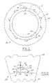
- Figure 1 schematically illustrates a ratchet one-way clutch assembly 20.
- the assembly 20 includes an inner race 22, an outer race 24, and a plurality of individual pawl members 25.
- the pawl members 25 are positioned in pockets 26 in the outer race member.
- a plurality of notches 28 are positioned in the outer circumference or periphery of the inner race 22.
- FIG 2 is an enlarged view of a portion of the clutch assembly shown in Figure 1.
- the pawl 25 shown in Figure 2 is depicted in the free-wheeling position.
- the cross-section of the pawl 25 has a peak or pivot ridge 30 formed by the intersection of two substantially flat sides 32 and 34.
- the peak 30 of the cross-section forms a pivot ridge with the outer race pocket 26 which is shaped to receive the pawl.
- the pocket 26 has substantially straight sides 36, 37, 38 and 39.
- the center of mass (CM) of the pawl 25 is positioned to the left of the pivot ridge 30 as viewed in accordance with Figure 2.
- a centrifugal force (CF) on the center of mass (CM) causes the pawl 25 to move toward the engaged position, that is, the position where it would be engaged with notch 28 in the inner race 22.
- the torque on the pawl 25 is proportional to the tangential distance of the CM away from the ridge 30.
- FIG. 1 and 2 shows a pawl member with the center of mass positioned, together with the pocket in the outer race, such that the pawl has a tendency to move toward the engaged position
- the geometry of the pawl can be changed to provide a pawl with a disengaging tendency.
- the CM could be positioned to the right of the pivot ridge 30.
- the pocket 26 in the outer race also has a peak or recess 40 which mates with the pivot ridge 30 of the pawl member 25. The peak 40 in the pocket holds the pawl 25 in the proper circumferential location for free movement in the pocket.
- the ridge on the pawl is precisely located relative to the center of mass of the pawl, regardless of the exact location of the pawl with respect to the outer race. This allows precise control of the engaging force, which is preferred for high speed operation. This is also accomplished with a relatively simple geometry which does not include an axle, separate pivot member, or the like.
- the outer race pocket is shaped such that it also has a corresponding peak or recess, which retains the pawl in a precise location in the pocket. This location prevents the pawl from contacting the sides or ends of the pocket as it rotates toward engagement.
- the pawl members 25 are made of a hardened steel material and formed by pieces cut from a drawn wire. This allows precise control of the geometry of the pawl, and also allows precise control of the center of mass relative to the peak or pivot ridge 30. In this regard, with the present invention, it is possible to control the center of mass within a tolerance of 0.001 inches (0.0025cm).
- the clutch as described above does not embody the invention claimed herein because it does have a garter spring member.
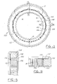
- An embodiment of the present invention is shown in Figures 3-8. This embodiment is referred to generally by the reference numeral 50 in the drawings.
- a spring is used to provide a tilting force on the pawl members 30 toward engagement.
- the assembly 50 includes an outer race member 52, an inner race member 54, a plurality of pawl members 56, and a pair of garter springs 58 and 60.
- a pair of retainment washers 62 and 64 are also provided in the embodiment shown in Figure 3 and are discussed further below.
- the pawl members 56 are positioned in pockets 66 in the outer race members 52 and are adapted to engage with notches 68 in the inner race 54.
- the garter springs 58 and 60 are made from a small coil of wire and are commonly available.
- pawl member 56 is utilized as shown in Figure 8.
- the pawl member 56 has a pair of recesses or side grooves 70 and 72.
- the garter springs 58 and 60 are positioned in the grooves 70 and 72 when the pawl members are positioned in the outer race.
- the remainder of the pawl members 56 have sizes and shapes similar to pawl members 25 described above with respect to Figures 1 and 2.
- the pawl members have a pivot ridge 74 which mates with a peak or recess 76 in the pocket 66.
- the operation of the spring members 58 and 60 is shown with reference to spring 58 and pawl members 56 in Figure 7.
- the garter spring 58 provides a force toward outer race member (24) and thus toward the engaging position of the pawl member.
- This spring provides a force F (as shown in Figure 7) against surface 80 of each of the pawl members.
- the spring member 58 is relaxed and does not provide a spring force on the pawl members. This is shown with respect to the center pawl member 56 in Figure 7.
- the spring force can also be arranged to act on a single side groove or a center groove of the pawl geometry. This is shown in Figures 9 and 10, respectively, where the pawl members are referred to by the reference numbers 82 and 84.
- the garter spring is indicated in phantom lines and is referred to by reference numeral 86. If either of the pawl embodiments shown in Figures 9 and 10 are utilized with the embodiment of the invention shown in Figures 3-7, then the position of the garter spring and the number of garter springs provided is adjusted accordingly.
- Opening or aperture 81 in the drawings provides an access hole for lubrication relative to the transmission or other mechanism in which the one-way clutch assembly 50 is utilized.
- several access holes are provided in the clutch assembly, such as the three openings 81 shown in Figure 12.
- the washers 62 and 64 are also known as axial retainment devices or members and can be used to improve or enhance the operation of the present invention.
- the members 62 and 64 retain the pawl members axially (longitudinally) in the clutch assemblies.
- the retainment members also hold the inner and outer races in axial alignment, while allowing free relative rotation.
- the axial retainment members act as thrust bearings between the clutch assembly and external parts of the mechanism that are rotating relative to the clutch assembly and must carry an axial load through the assembly.
- the axial retainment members (washers) 62 and 64 can retain lubrication in the clutch assembly which is required to prevent excess wear of the pawl members.
- the washers 62 and 64 can be connected to the outer race through a press-fit arrangement, staking, welding, or mechanical fastening in any conventional manner.
- FIG. 1 An injection molded plastic retainer member can also be utilized.
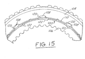
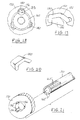
- a member 100 is shown in Figures 11-15.
- the one-way ratchet clutch assembly is referred to generally by the reference numeral 102.
- the assembly 102 includes an outer race member 104, an inner race member 106, a plurality of pawl members 108, a garter spring member 110 and a second retainment member 112.
- the pawl members 108 can be of any of the types shown and described earlier.
- the pawl members 108 are contained in pockets 120 in the outer race member and engage notches 122 in the inner race member, in the same manner described above with reference to the other Figures.
- the retaining member 100 has a plurality of flanges or upstanding arcuate shaped guide members 118 situated to be positioned within the annular space between the inner and outer races 106 and 104, respectively.
- the member 100 is a radial bearing retainer for the pawls and the race members, and also acts as a lube dam for lubrication.
- the retainer members 100 and 112 are preferably attached together to retain the clutch assembly together axially.
- the retainer members also act as thrust bearings between the assembly and external parts of the mechanism that are rotating relative to the clutch assembly and carry axial loads through the assembly.
- the retainer member 100 is made from an injection molded plastic material, and also preferably has a low friction coefficient so that it can provide improved bearing performance over regular steel-on-steel bearings.
- the retainer members 100 and 112 can be connected together in any conventional manner, such as a press-fit arrangement, staking, ultrasonic welding, mechanical fastening, and the like.
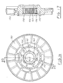
- the pawl pocket members are incorporated directly as part of a stator or reactor member 150 for a torque converter or the like.
- the member 150 can be any integral part which would require a one-way clutch mechanism.
- the member 150 is made from an aluminum, plastic or another material which can be cast and machined relatively easily.
- a plurality of pocket members 152 are formed and/or machined directly into the inner diameter surface 154 of the member 150.
- the pawl members 156 which are positioned in the pockets 152, can be of any of the types shown and described herein, and can be urged toward the engaged position by one of the various types of spring members or mechanisms, as discussed herein.
- the inner member 160 can be any typical inner race member of the type discussed above with a plurality of locking notches 162 positioned around its outer circumference 164.
- the central shaft member which typically mates with the inner race member by mating teeth or spline members 166 or the like, can have the notches machined or formed directly on the outer circumference of the shaft, thereby eliminating the inner race member.
- Such an embodiment is shown in Figure 21 wherein a plurality of notches 162' are provided on shaft member 170, which typically is hollow, and the shaft member is then mated with member 172 which can be an outer race member, a stator or reactor member, or the like.
- Shaft member 170 can be, for example, part of a vehicle transmission.
- any number of pockets and notches can be provided as desired by the clutch designer and/or in accordance with the operating specifications and parameters for the clutch mechanism.
- three pockets and pawl members are provided and uniformly spaced around the inner circumference/diameter of the outer member 150.
- seventeen notches are provided in the inner member.
- Figures 18-20 depict an alternate embodiment of the invention in which insert members 180 are provided.
- the insert members 180 are made from steel or another hard or hardened material and are used to prevent damage to softer materials which might be utilized for the outer stator, reactor or other member 150 when the clutch mechanism is utilized.
- the inserts can be made of stamped steel or the like.
- the pocket members 182 in the member 150 are provided with a larger space or area, to allow positioning of the insert members 180 therein.
- the insert members are press fit, wedged or otherwise permanently secured in the pockets 182.
- the pawl members 156 are positioned inside the cupped insert members as shown.
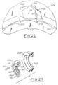
- FIG. 22 Another preferred embodiment of the present invention is shown in Figure 22.
- 25 the pawl member 200 has a different size and shape from the pawl members shown above.
- the pawl members 200 have a greater height H in the radial direction. This is to increase the load-carrying capacity of the clutch mechanism.
- the pawl member 200 is positioned in a pocket 202 in an outer member 204, which can be an outer race, a stator or reactor, or the like.
- the center of mass CM of the pawl member 200 is preferably positioned as shown relative to the peak or pivot ridge 206 such that a pawl engaging force is generated upon rotation of the outer member 204.
- a plurality of notches 210 are formed in the inner member 212, which can be an inner race, a shaft member, or the like.
- the outer member as an insert which is combined with a stator, reactor or other mechanical member.
- the outer member 220 has an annular shape and is adapted to fit within cavity or recess 222 in the stator, reactor or other member 224.
- the outer member 220 which preferably is made from a metal material, can be press fit or keyed by key member 226 into the member 224. In this manner, the member 224 can be made from a lower cost material, such as a plastic material.
- the other portion of the clutch mechanism, including the inner member 160, pawl members 156 and the like are the same as those set forth above.
Landscapes
- Engineering & Computer Science (AREA)
- General Engineering & Computer Science (AREA)
- Mechanical Engineering (AREA)
- Mechanical Operated Clutches (AREA)
- One-Way And Automatic Clutches, And Combinations Of Different Clutches (AREA)
- Impression-Transfer Materials And Handling Thereof (AREA)
- Transmission Devices (AREA)
- Mounting Of Bearings Or Others (AREA)
Applications Claiming Priority (5)
| Application Number | Priority Date | Filing Date | Title |
|---|---|---|---|
| US707104 | 1996-09-03 | ||
| US08/707,104 US5853073A (en) | 1996-09-03 | 1996-09-03 | Ratchet one-way clutch assembly |
| US917880 | 1997-08-27 | ||
| US08/917,880 US5947245A (en) | 1996-09-03 | 1997-08-27 | Combined stator and ratchet clutch assembly |
| EP97939741A EP0923680B1 (fr) | 1996-09-03 | 1997-09-02 | Ensemble d'embrayage a roue libre a rochets |
Related Parent Applications (1)
| Application Number | Title | Priority Date | Filing Date |
|---|---|---|---|
| EP97939741A Division EP0923680B1 (fr) | 1996-09-03 | 1997-09-02 | Ensemble d'embrayage a roue libre a rochets |
Publications (3)
| Publication Number | Publication Date |
|---|---|
| EP1108914A2 true EP1108914A2 (fr) | 2001-06-20 |
| EP1108914A3 EP1108914A3 (fr) | 2002-01-02 |
| EP1108914B1 EP1108914B1 (fr) | 2005-03-16 |
Family
ID=24840362
Family Applications (2)
| Application Number | Title | Priority Date | Filing Date |
|---|---|---|---|
| EP01200306A Expired - Lifetime EP1108914B1 (fr) | 1996-09-03 | 1997-09-02 | Embrayage à roue libre à crochets |
| EP02078324A Expired - Lifetime EP1265000B1 (fr) | 1996-09-03 | 1997-09-02 | Ensemble d'embrayage à roue libre à rochets |
Family Applications After (1)
| Application Number | Title | Priority Date | Filing Date |
|---|---|---|---|
| EP02078324A Expired - Lifetime EP1265000B1 (fr) | 1996-09-03 | 1997-09-02 | Ensemble d'embrayage à roue libre à rochets |
Country Status (4)
| Country | Link |
|---|---|
| US (4) | US5853073A (fr) |
| EP (2) | EP1108914B1 (fr) |
| JP (1) | JP2008241044A (fr) |
| DE (1) | DE69739960D1 (fr) |
Cited By (1)
| Publication number | Priority date | Publication date | Assignee | Title |
|---|---|---|---|---|
| EP4488539A1 (fr) * | 2023-07-06 | 2025-01-08 | SRAM Deutschland GmbH | Moyeu à roue libre avec dispositif à corps de blocage |
Families Citing this family (90)
| Publication number | Priority date | Publication date | Assignee | Title |
|---|---|---|---|---|
| US6125979A (en) * | 1996-09-03 | 2000-10-03 | Borgwagner Inc. | Ratchet one-way clutch assembly with restraining members |
| US6338403B1 (en) * | 1996-09-03 | 2002-01-15 | Borgwarner Inc. | Ratchet clutch with bearing surfaces |
| US5853073A (en) * | 1996-09-03 | 1998-12-29 | Borg-Warner Automotive, Inc. | Ratchet one-way clutch assembly |
| US5971122A (en) * | 1996-09-03 | 1999-10-26 | Borg-Warner Automotive, Inc. | Ratchet one-way clutch assembly unit with wide biasing springs |
| US6062362A (en) * | 1996-09-03 | 2000-05-16 | Borg-Warner Automotive, Inc. | Ratchet one-way clutch with stator |
| US6148979A (en) * | 1998-01-20 | 2000-11-21 | Brigham Young University | Compliant overrunning clutch with centrifugal throw-out |
| NL1013449C2 (nl) * | 1999-11-01 | 2001-05-02 | Skf Eng & Res Centre Bv | Eenwegkoppeling. |
| US6557681B2 (en) | 2000-01-26 | 2003-05-06 | Nsk-Warner K.K. | Ratchet type one-way clutch and method of manufacturing the same |
| US6607465B1 (en) * | 2000-03-10 | 2003-08-19 | Shimano, Inc. | Bicycle hub transmission with a guiding member for a sun gear |
| DE10025720C2 (de) | 2000-05-25 | 2002-05-29 | Walterscheid Gmbh Gkn | Antriebsanordnung mit Freilaufkupplung |
| US6332520B1 (en) | 2000-06-14 | 2001-12-25 | Borgwarner Inc. | Planar ratchet one way clutch |
| JP2002005202A (ja) * | 2000-06-22 | 2002-01-09 | Nsk Warner Kk | ラチェット型ワンウェイクラッチ |
| JP2002013559A (ja) * | 2000-06-30 | 2002-01-18 | Nsk Warner Kk | ラチェット型ワンウェイクラッチ |
| IT1316008B1 (it) * | 2000-11-14 | 2003-03-26 | Igino Aurora | Innesto di sopravanzo con usura e rumorosita' ridotte. |
| US6757975B1 (en) | 2001-01-25 | 2004-07-06 | Brigham Young University | Multi-layered compliant mechanisms and method of manufacture |
| US6571926B2 (en) * | 2001-02-12 | 2003-06-03 | Means Industries, Inc. | One-way clutch assembly featuring improved strut stability |
| JP2002310200A (ja) | 2001-04-12 | 2002-10-23 | Nsk Warner Kk | ワンウェイクラッチ組立体 |
| US6575279B2 (en) | 2001-05-29 | 2003-06-10 | Borgwarner Inc. | Laminated one way clutch race |
| JP2003028204A (ja) * | 2001-07-17 | 2003-01-29 | Nsk Warner Kk | ラチェットワンウェイクラッチ及びラチェットワンウェイクラッチを用いたステータ |
| JP2003343689A (ja) * | 2002-05-31 | 2003-12-03 | Nsk Warner Kk | ステータ |
| US6997295B2 (en) | 2002-07-03 | 2006-02-14 | Pederson Jack E | Clutch having elements capable of independent operation |
| US7160351B2 (en) * | 2002-10-01 | 2007-01-09 | Pmg Ohio Corp. | Powder metal clutch races for one-way clutches and method of manufacture |
| US6832674B2 (en) * | 2002-12-05 | 2004-12-21 | Borgwarner, Inc. | Bi-directional four-mode clutch |
| US6854577B2 (en) * | 2003-04-29 | 2005-02-15 | Means Industries, Inc. | Sound dampened one-way clutch |
| US6905009B2 (en) * | 2003-05-30 | 2005-06-14 | Borgwarner, Inc. | Bi-directional clutch having a momentary latching actuator |
| US6830531B1 (en) | 2003-07-24 | 2004-12-14 | Borgwarner, Inc. | Control strategy for load sharing between a friction clutch and one-way clutch to effect low and reverse gear ratios in a transmission |
| US7101306B2 (en) * | 2004-04-30 | 2006-09-05 | Borgwarner Inc. | Bi-directional four-mode clutch for providing low and reverse gear ratios in a transmission |
| US7614486B2 (en) * | 2004-07-27 | 2009-11-10 | Ford Global Technologies, Llc | Retention of an actuating spring in a one-way clutch or brake |
| US20060021838A1 (en) * | 2004-07-27 | 2006-02-02 | John Kimes | Ratcheting one-way clutch having piloted surfaces |
| US7383930B2 (en) * | 2004-07-27 | 2008-06-10 | Ford Global Technologies, Inc. | Overrunning clutch |
| US7661518B2 (en) * | 2004-07-27 | 2010-02-16 | Ford Global Technologies, Llc | Preventing ratcheting on rockers of a one-way clutch |
| US7455157B2 (en) * | 2004-07-27 | 2008-11-25 | Ford Global Technologies, Llc | Ratcheting one-way clutch having rockers |
| US7100756B2 (en) | 2004-07-27 | 2006-09-05 | Ford Global Technologies, Llc | Overrunning clutch |
| US7500548B2 (en) | 2004-07-27 | 2009-03-10 | Ford Global Technologies, Llc | Dual-mode one-way torque transmitting device |
| US7448481B2 (en) * | 2004-07-27 | 2008-11-11 | Ford Global Technologies, Llc | Ratcheting one-way clutch having rockers actuated by centrifugal force |
| US7451862B2 (en) * | 2004-07-27 | 2008-11-18 | Ford Global Technologies, Llc | Ratcheting one-way clutch having rockers retained in closed pockets |
| US7455156B2 (en) * | 2004-07-27 | 2008-11-25 | Ford Global Technologies, Llc | Overrunning clutch |
| US7223198B2 (en) * | 2004-07-27 | 2007-05-29 | Ford Global Technologies, Llc | Automatic transmission carrier assembly including an overrunning brake |
| EP1712811A1 (fr) * | 2005-04-15 | 2006-10-18 | Campagnolo S.R.L. | Mécanisme roue-libre pour moyeux de roue arrière de bicyclette, corps de support de cliquets pour un tel méchanisme et moyeux comprenant un tel méchanisme |
| CA2620887A1 (fr) * | 2005-09-02 | 2007-03-08 | Gkn Sinter Metals, Inc. | Roue libre |
| JP2009531608A (ja) * | 2006-03-24 | 2009-09-03 | ルーク ラメレン ウント クツプルングスバウ ベタイリグングス コマンディートゲゼルシャフト | 統合されたステータを有する一方向クラッチ |
| WO2007110020A1 (fr) * | 2006-03-24 | 2007-10-04 | Luk Lamellen Und Kupplungsbau Beteiligungs Kg | Modules avec un stator et un couplage unidirectionnel pour convertisseur de couple |
| WO2007110021A1 (fr) * | 2006-03-24 | 2007-10-04 | Luk Lamellen Und Kupplungsbau Beteiligungs Kg | Embrayage à cliquets unidirectionnel pourvu d'un dispositif d'amortissement |
| US20080083595A1 (en) * | 2006-05-19 | 2008-04-10 | Spiegel Clinton J | Multi-tooth pawl type gearing mechanism |
| US8491439B2 (en) | 2007-02-06 | 2013-07-23 | Ford Global Technologies, Llc | Selectively controlled rocker one-way clutch |
| DE102008059188A1 (de) * | 2008-11-27 | 2010-06-02 | Schaeffler Kg | Freilaufkupplung |
| WO2010077560A2 (fr) | 2008-12-09 | 2010-07-08 | Borgwarner Inc. | Transmission automatique pour véhicule hybride |
| WO2010069253A1 (fr) * | 2008-12-16 | 2010-06-24 | 苏州宝时得电动工具有限公司 | Scie à chaîne |
| DE102008064153A1 (de) | 2008-12-19 | 2010-07-01 | Schaeffler Technologies Gmbh & Co. Kg | Formschlüssige Freilaufkupplung |
| EP2430292A1 (fr) | 2009-05-12 | 2012-03-21 | Icr Turbine Engine Corporation | Système de stockage et de conversion d'énergie de turbine à gaz |
| US9086170B2 (en) | 2009-06-29 | 2015-07-21 | Borgwarner Inc. | Hydraulic valve for use in a control module of an automatic transmission |
| US8851786B2 (en) * | 2009-12-01 | 2014-10-07 | Lockhead Martin Corporation | Bulkhead sealing mechanism |
| US8866334B2 (en) | 2010-03-02 | 2014-10-21 | Icr Turbine Engine Corporation | Dispatchable power from a renewable energy facility |
| US8984895B2 (en) | 2010-07-09 | 2015-03-24 | Icr Turbine Engine Corporation | Metallic ceramic spool for a gas turbine engine |
| GB201105163D0 (en) | 2010-08-30 | 2011-05-11 | American Grease Stick Co | Wrench ratchet mechanisms and wrenches |
| CA2813680A1 (fr) | 2010-09-03 | 2012-03-08 | Icr Turbine Engine Corporation | Configurations de moteur a turbine a gaz |
| US8899032B2 (en) | 2010-09-27 | 2014-12-02 | Schaeffler Technologies Gmbh & Co. Kg | Stator centering plate |
| US9541141B2 (en) | 2010-12-10 | 2017-01-10 | Means Industries, Inc. | Electronic vehicular transmission, controllable coupling assembly and coupling member for use in the assembly |
| US9127724B2 (en) | 2010-12-10 | 2015-09-08 | Means Industries, Inc. | Electromechanical apparatus for use with a coupling assembly and controllable coupling assembly including such apparatus |
| US9638266B2 (en) | 2010-12-10 | 2017-05-02 | Means Industries, Inc. | Electronic vehicular transmission including a sensor and coupling and control assembly for use therein |
| US9255614B2 (en) | 2010-12-10 | 2016-02-09 | Means Industries, Inc. | Electronic vehicular transmission and coupling and control assembly for use therein |
| US9234552B2 (en) | 2010-12-10 | 2016-01-12 | Means Industries, Inc. | Magnetic system for controlling the operating mode of an overrunning coupling assembly and overrunning coupling and magnetic control assembly having same |
| JP5885214B2 (ja) | 2010-12-10 | 2016-03-15 | ミーンズ インダストリーズ,インク. | 電気機械駆動式連結器および制御アセンブリ |
| US9051873B2 (en) | 2011-05-20 | 2015-06-09 | Icr Turbine Engine Corporation | Ceramic-to-metal turbine shaft attachment |
| US8844693B2 (en) | 2011-09-13 | 2014-09-30 | Means Industries, Inc. | Coupling assembly having an overrun mode and ratcheting reverse strut or radial ratchet for use therein |
| US8881516B2 (en) | 2012-02-17 | 2014-11-11 | Ford Global Technologies, Llc | One-way brake for a torque converter stator |
| US10094288B2 (en) | 2012-07-24 | 2018-10-09 | Icr Turbine Engine Corporation | Ceramic-to-metal turbine volute attachment for a gas turbine engine |
| WO2014142722A1 (fr) * | 2013-03-15 | 2014-09-18 | Husqvarna Ab | Scie à chaîne comprenant ensemble de molette auto-verrouillant |
| US9051980B2 (en) | 2013-04-26 | 2015-06-09 | Gm Global Technology Operations, Llc | Direction selectable sprag |
| US9249836B2 (en) | 2013-08-15 | 2016-02-02 | Means Industries, Inc. | Coupling assembly having reduced undesirable noise and contact stress caused by a transition between operating modes of the assembly |
| US9371868B2 (en) | 2013-08-27 | 2016-06-21 | Means Industries, Inc. | Coupling member subassembly for use in controllable coupling assembly and electromechanical apparatus having a pair of simultaneously actuated elements for use in the subassembly |
| WO2015033409A1 (fr) * | 2013-09-04 | 2015-03-12 | 三菱電機株式会社 | Embrayage à cames |
| US9482294B2 (en) | 2014-02-19 | 2016-11-01 | Means Industries, Inc. | Coupling and control assembly including a sensor |
| US9562574B2 (en) | 2014-02-19 | 2017-02-07 | Means Industries, Inc. | Controllable coupling assembly and coupling member for use in the assembly |
| JP2015169143A (ja) | 2014-03-07 | 2015-09-28 | 株式会社ジェイテクト | 発電装置及びこれに用いる軸継手装置 |
| CN106415045A (zh) * | 2014-03-27 | 2017-02-15 | 白永九 | 单向离合器及具备其的无级变速器 |
| US11028885B2 (en) | 2014-03-28 | 2021-06-08 | Keystone Powdered Metal Company | Two-way clutch assembly |
| US10208814B1 (en) | 2014-03-28 | 2019-02-19 | Keystone Powdered Metal Company | Two-way clutch assembly |
| US9909631B2 (en) | 2014-11-07 | 2018-03-06 | Means Industries, Inc. | Apparatus for controllably actuating a selectable coupling assembly having multiple operating modes |
| EP3277972A4 (fr) | 2015-04-01 | 2019-04-10 | Means Industries, Inc. | Transmission de véhicule électronique, ensemble de couplage pouvant être commandé et élément de couplage à utiliser dans l'ensemble |
| US9482297B2 (en) | 2015-04-01 | 2016-11-01 | Means Industries, Inc. | Controllable coupling assembly having forward and reverse backlash |
| US10145428B2 (en) | 2016-02-04 | 2018-12-04 | Means Industries, Inc. | Coupling assembly having an overrun mode and channeled locking member for use therein |
| CN109072657A (zh) * | 2016-03-10 | 2018-12-21 | 戴维·冯 | 耦合器 |
| US10316904B2 (en) | 2016-09-28 | 2019-06-11 | Means Industries, Inc. | Coupling assembly having an overrun mode and appendaged locking member for use therein |
| US10323700B2 (en) | 2017-02-22 | 2019-06-18 | Schaeffler Technologies AG & Co. KG | Wedge clutch with wedge plate segments, cage and wave spring and method thereof |
| WO2018157236A1 (fr) * | 2017-03-02 | 2018-09-07 | Magna Powertrain Inc. | Embrayage unidirectionnel à propriétés d'encliquetage améliorées |
| US10451120B2 (en) | 2017-03-21 | 2019-10-22 | Schaeffler Technologies AG & Co. KG | Three-way switchable clutch |
| US11346404B2 (en) | 2018-10-09 | 2022-05-31 | Means Industries, Inc. | Coupling and control assembly for use in a motor vehicle |
| US10871194B2 (en) | 2019-01-31 | 2020-12-22 | Schaeffler Technologies AG & Co. KG | Switchable ratcheting wedge clutch |
| US11739801B2 (en) | 2020-06-02 | 2023-08-29 | Means Industries, Inc. | Coupling assembly and ratcheting locking member for use therein |
Citations (6)
| Publication number | Priority date | Publication date | Assignee | Title |
|---|---|---|---|---|
| GB190602116A (en) | 1906-01-27 | 1907-01-26 | Harry Charles Andrews | A Freewheel Clutch for Cycles, Motor Cycles and such like Machines |
| DE375047C (de) | 1921-07-01 | 1923-05-04 | Auto Debrayage T L Sa | Klinkenschaltwerk fuer Motorwagen, bei dem die Schaltklinken in Aussparungen einer auf der Motorwelle sitzenden Scheibe angeordnet sind |
| US2226247A (en) | 1938-09-28 | 1940-12-24 | Lesage Alfred | Freewheel locking device, more particularly for the hub of bicycles |
| US3554340A (en) | 1968-10-02 | 1971-01-12 | Keizo Shimano | Free wheel for a bicycle |
| EP0471349A1 (fr) | 1990-08-14 | 1992-02-19 | Fichtel & Sachs AG | Mécanisme roue-libre à cliquets pour moyeux de bicyclette |
| US5449057A (en) | 1993-10-26 | 1995-09-12 | Frank; Arthur R. | One-way clutch apparatus |
Family Cites Families (29)
| Publication number | Priority date | Publication date | Assignee | Title |
|---|---|---|---|---|
| DE139815C (fr) * | ||||
| GB190702116A (en) * | 1907-01-28 | 1907-06-13 | Philip Arthur Newton | Improvements in Front Stop and Gripper Operating Mechanism for Printing Machines |
| US1767593A (en) * | 1927-11-09 | 1930-06-24 | Cutler Hammer Inc | Clutch |
| US1883966A (en) * | 1930-09-20 | 1932-10-25 | Frank R Krause | Overrunning clutch |
| US2323353A (en) * | 1940-12-18 | 1943-07-06 | William H Plog | One-way clutch |
| US2710504A (en) * | 1952-06-06 | 1955-06-14 | Adiel Y Dodge | Toroidal chamber type hydraulic torque converter |
| NL293458A (fr) * | 1962-06-01 | |||
| US3233471A (en) * | 1963-05-06 | 1966-02-08 | Patent & Dev Inc | Power take-off connection |
| GB1135818A (en) * | 1966-06-10 | 1968-12-04 | Honda Gijutsu Kenkyusho Kk | Improvements in or relating to free wheel mechanisms |
| US3486586A (en) * | 1967-12-22 | 1969-12-30 | Joseph H Grier Jr | Pedal crank actuated bicycle wheel rim brakes |
| FR2267464A1 (en) * | 1974-04-11 | 1975-11-07 | Flam Joseph | Air circulating device for drying room - has two sheets of metal welded together along tips and spindle |
| GB1598908A (en) * | 1976-10-27 | 1981-09-23 | Borecliff Ltd | Freewheel devices |
| JPS56157435A (en) * | 1980-05-07 | 1981-12-04 | Ube Ind Ltd | Preparation of gas separating membrane |
| JPS585537A (ja) * | 1981-06-30 | 1983-01-12 | Toshiba Corp | ラチエツト式自由回転クラツチ |
| JPS5896135A (ja) * | 1981-12-03 | 1983-06-08 | Honda Motor Co Ltd | 内燃機関の弁駆動制御装置 |
| JPS6022210B2 (ja) * | 1983-12-12 | 1985-05-31 | 株式会社日立製作所 | 同期歯車継手 |
| DD297493A5 (de) * | 1989-07-06 | 1992-01-09 | ��@���������@�������k�� | Freilaufkupplung |
| DE3922222A1 (de) * | 1989-07-06 | 1991-01-24 | Walterscheid Gmbh Jean | Freilaufkupplung |
| DE4006232C2 (de) * | 1990-02-28 | 1994-03-03 | Walterscheid Gmbh Gkn | Freilauf für zwei Antriebsdrehrichtungen |
| US5064037A (en) * | 1990-03-01 | 1991-11-12 | Long Jr Thomas F | One-way acting sprag clutch with centrifugal disengagement from the outer race |
| DE4026211C1 (fr) | 1990-08-18 | 1992-01-23 | Jean Walterscheid Gmbh, 5204 Lohmar, De | |
| US5065635A (en) * | 1990-09-14 | 1991-11-19 | Westinghouse Electric Corp. | Apparatus and method for inspecting an item having grooves machined therein |
| US5445255A (en) * | 1993-07-08 | 1995-08-29 | Borg-Warner Automotive, Inc. | Sprag one-way clutch with inertia resistance members |
| JPH0735164A (ja) * | 1993-07-26 | 1995-02-03 | Yamaha Motor Co Ltd | 一方向クラッチ |
| FR2716944A1 (fr) * | 1994-03-05 | 1995-09-08 | Gkn Automotive Ag | Procédé de fabrication d'une partie de joint extérieure, notamment d'un joint à tripode, et pièce ainsi obtenue. |
| DE4411515C1 (de) * | 1994-04-02 | 1995-08-03 | Gkn Automotive Ag | Gelenkaußenteil für ein Gleichlaufdrehgelenk und Verfahren zu dessen Herstellung |
| DE4445634C2 (de) * | 1994-12-21 | 1997-10-16 | Walterscheid Gmbh Gkn | Kupplung |
| US5690202A (en) * | 1996-04-15 | 1997-11-25 | Myers; John E. | Overrunning clutch mechanism |
| US5853073A (en) * | 1996-09-03 | 1998-12-29 | Borg-Warner Automotive, Inc. | Ratchet one-way clutch assembly |
-
1996
- 1996-09-03 US US08/707,104 patent/US5853073A/en not_active Expired - Lifetime
-
1997
- 1997-08-27 US US08/917,880 patent/US5947245A/en not_active Expired - Fee Related
- 1997-09-02 DE DE69739960T patent/DE69739960D1/de not_active Expired - Lifetime
- 1997-09-02 EP EP01200306A patent/EP1108914B1/fr not_active Expired - Lifetime
- 1997-09-02 EP EP02078324A patent/EP1265000B1/fr not_active Expired - Lifetime
-
1998
- 1998-07-10 US US09/113,680 patent/US5954174A/en not_active Expired - Fee Related
-
1999
- 1999-09-07 US US09/390,439 patent/US6109410A/en not_active Expired - Fee Related
-
2008
- 2008-05-23 JP JP2008135018A patent/JP2008241044A/ja active Pending
Patent Citations (6)
| Publication number | Priority date | Publication date | Assignee | Title |
|---|---|---|---|---|
| GB190602116A (en) | 1906-01-27 | 1907-01-26 | Harry Charles Andrews | A Freewheel Clutch for Cycles, Motor Cycles and such like Machines |
| DE375047C (de) | 1921-07-01 | 1923-05-04 | Auto Debrayage T L Sa | Klinkenschaltwerk fuer Motorwagen, bei dem die Schaltklinken in Aussparungen einer auf der Motorwelle sitzenden Scheibe angeordnet sind |
| US2226247A (en) | 1938-09-28 | 1940-12-24 | Lesage Alfred | Freewheel locking device, more particularly for the hub of bicycles |
| US3554340A (en) | 1968-10-02 | 1971-01-12 | Keizo Shimano | Free wheel for a bicycle |
| EP0471349A1 (fr) | 1990-08-14 | 1992-02-19 | Fichtel & Sachs AG | Mécanisme roue-libre à cliquets pour moyeux de bicyclette |
| US5449057A (en) | 1993-10-26 | 1995-09-12 | Frank; Arthur R. | One-way clutch apparatus |
Cited By (1)
| Publication number | Priority date | Publication date | Assignee | Title |
|---|---|---|---|---|
| EP4488539A1 (fr) * | 2023-07-06 | 2025-01-08 | SRAM Deutschland GmbH | Moyeu à roue libre avec dispositif à corps de blocage |
Also Published As
| Publication number | Publication date |
|---|---|
| US5853073A (en) | 1998-12-29 |
| EP1265000A3 (fr) | 2007-06-27 |
| US6109410A (en) | 2000-08-29 |
| EP1265000B1 (fr) | 2010-08-11 |
| US5947245A (en) | 1999-09-07 |
| US5954174A (en) | 1999-09-21 |
| DE69739960D1 (de) | 2010-09-23 |
| JP2008241044A (ja) | 2008-10-09 |
| EP1108914A3 (fr) | 2002-01-02 |
| EP1265000A2 (fr) | 2002-12-11 |
| EP1108914B1 (fr) | 2005-03-16 |
Similar Documents
| Publication | Publication Date | Title |
|---|---|---|
| EP1108914B1 (fr) | Embrayage à roue libre à crochets | |
| EP1066477B1 (fr) | Embrayage a roue libre a rochets | |
| EP0923680B1 (fr) | Ensemble d'embrayage a roue libre a rochets | |
| EP1862690B1 (fr) | Embrayage à rochet doté de surfaces porteuses | |
| US6062362A (en) | Ratchet one-way clutch with stator | |
| EP1031752B1 (fr) | Ensemble d'embrayage à roue libre à crochets avec des eléments de retenue | |
| EP1056959B1 (fr) | Ensemble de couplage a roue libre et procede de fabrication dudit ensemble | |
| JPH049930B2 (fr) | ||
| JP2009079773A (ja) | ワンウエイラチェットクラッチ組立体 |
Legal Events
| Date | Code | Title | Description |
|---|---|---|---|
| PUAI | Public reference made under article 153(3) epc to a published international application that has entered the european phase |
Free format text: ORIGINAL CODE: 0009012 |
|
| AC | Divisional application: reference to earlier application |
Ref document number: 923680 Country of ref document: EP |
|
| AK | Designated contracting states |
Kind code of ref document: A2 Designated state(s): DE FR GB |
|
| RIN1 | Information on inventor provided before grant (corrected) |
Inventor name: COSTIN, DANIEL P. Inventor name: BACON, DUANE A. |
|
| PUAL | Search report despatched |
Free format text: ORIGINAL CODE: 0009013 |
|
| AK | Designated contracting states |
Kind code of ref document: A3 Designated state(s): DE FR GB |
|
| 17P | Request for examination filed |
Effective date: 20020121 |
|
| AKX | Designation fees paid |
Free format text: DE FR GB |
|
| 17Q | First examination report despatched |
Effective date: 20040219 |
|
| GRAP | Despatch of communication of intention to grant a patent |
Free format text: ORIGINAL CODE: EPIDOSNIGR1 |
|
| GRAS | Grant fee paid |
Free format text: ORIGINAL CODE: EPIDOSNIGR3 |
|
| GRAA | (expected) grant |
Free format text: ORIGINAL CODE: 0009210 |
|
| AC | Divisional application: reference to earlier application |
Ref document number: 0923680 Country of ref document: EP Kind code of ref document: P |
|
| AK | Designated contracting states |
Kind code of ref document: B1 Designated state(s): DE FR GB |
|
| REG | Reference to a national code |
Ref country code: GB Ref legal event code: FG4D |
|
| RAP2 | Party data changed (patent owner data changed or rights of a patent transferred) |
Owner name: BORGWARNER INC. |
|
| REF | Corresponds to: |
Ref document number: 69732803 Country of ref document: DE Date of ref document: 20050421 Kind code of ref document: P |
|
| RAP2 | Party data changed (patent owner data changed or rights of a patent transferred) |
Owner name: BORGWARNER INC. |
|
| ET | Fr: translation filed | ||
| PLBE | No opposition filed within time limit |
Free format text: ORIGINAL CODE: 0009261 |
|
| STAA | Information on the status of an ep patent application or granted ep patent |
Free format text: STATUS: NO OPPOSITION FILED WITHIN TIME LIMIT |
|
| 26N | No opposition filed |
Effective date: 20051219 |
|
| PGFP | Annual fee paid to national office [announced via postgrant information from national office to epo] |
Ref country code: GB Payment date: 20090807 Year of fee payment: 13 |
|
| PGFP | Annual fee paid to national office [announced via postgrant information from national office to epo] |
Ref country code: FR Payment date: 20100920 Year of fee payment: 14 |
|
| PGFP | Annual fee paid to national office [announced via postgrant information from national office to epo] |
Ref country code: DE Payment date: 20100930 Year of fee payment: 14 |
|
| GBPC | Gb: european patent ceased through non-payment of renewal fee |
Effective date: 20100902 |
|
| PG25 | Lapsed in a contracting state [announced via postgrant information from national office to epo] |
Ref country code: GB Free format text: LAPSE BECAUSE OF NON-PAYMENT OF DUE FEES Effective date: 20100902 |
|
| REG | Reference to a national code |
Ref country code: FR Ref legal event code: ST Effective date: 20120531 |
|
| REG | Reference to a national code |
Ref country code: DE Ref legal event code: R119 Ref document number: 69732803 Country of ref document: DE Effective date: 20120403 |
|
| PG25 | Lapsed in a contracting state [announced via postgrant information from national office to epo] |
Ref country code: DE Free format text: LAPSE BECAUSE OF NON-PAYMENT OF DUE FEES Effective date: 20120403 |
|
| PG25 | Lapsed in a contracting state [announced via postgrant information from national office to epo] |
Ref country code: FR Free format text: LAPSE BECAUSE OF NON-PAYMENT OF DUE FEES Effective date: 20110930 |