EP1109080A2 - Rouleau chauffant - Google Patents
Rouleau chauffant Download PDFInfo
- Publication number
- EP1109080A2 EP1109080A2 EP00126802A EP00126802A EP1109080A2 EP 1109080 A2 EP1109080 A2 EP 1109080A2 EP 00126802 A EP00126802 A EP 00126802A EP 00126802 A EP00126802 A EP 00126802A EP 1109080 A2 EP1109080 A2 EP 1109080A2
- Authority
- EP
- European Patent Office
- Prior art keywords
- heat roller
- gas
- metallic substrate
- thermal conductivity
- enclosed gas
- Prior art date
- Legal status (The legal status is an assumption and is not a legal conclusion. Google has not performed a legal analysis and makes no representation as to the accuracy of the status listed.)
- Granted
Links
- 238000010438 heat treatment Methods 0.000 claims abstract description 44
- 239000000758 substrate Substances 0.000 claims abstract description 36
- 239000007789 gas Substances 0.000 claims description 79
- XKRFYHLGVUSROY-UHFFFAOYSA-N Argon Chemical compound [Ar] XKRFYHLGVUSROY-UHFFFAOYSA-N 0.000 claims description 36
- 229910052786 argon Inorganic materials 0.000 claims description 18
- WKBOTKDWSSQWDR-UHFFFAOYSA-N Bromine atom Chemical compound [Br] WKBOTKDWSSQWDR-UHFFFAOYSA-N 0.000 claims description 14
- GDTBXPJZTBHREO-UHFFFAOYSA-N bromine Substances BrBr GDTBXPJZTBHREO-UHFFFAOYSA-N 0.000 claims description 14
- 229910052794 bromium Inorganic materials 0.000 claims description 14
- 229910052743 krypton Inorganic materials 0.000 claims description 12
- DNNSSWSSYDEUBZ-UHFFFAOYSA-N krypton atom Chemical compound [Kr] DNNSSWSSYDEUBZ-UHFFFAOYSA-N 0.000 claims description 12
- 229910052724 xenon Inorganic materials 0.000 claims description 10
- FHNFHKCVQCLJFQ-UHFFFAOYSA-N xenon atom Chemical compound [Xe] FHNFHKCVQCLJFQ-UHFFFAOYSA-N 0.000 claims description 10
- 229910052736 halogen Inorganic materials 0.000 claims description 6
- 150000002367 halogens Chemical class 0.000 claims description 6
- 239000000203 mixture Substances 0.000 claims 4
- 238000002474 experimental method Methods 0.000 description 5
- 239000000463 material Substances 0.000 description 4
- 238000010521 absorption reaction Methods 0.000 description 2
- 230000007423 decrease Effects 0.000 description 2
- 238000005259 measurement Methods 0.000 description 2
- 229910052782 aluminium Inorganic materials 0.000 description 1
- XAGFODPZIPBFFR-UHFFFAOYSA-N aluminium Chemical compound [Al] XAGFODPZIPBFFR-UHFFFAOYSA-N 0.000 description 1
- 230000003247 decreasing effect Effects 0.000 description 1
- 238000011835 investigation Methods 0.000 description 1
- 229910052751 metal Inorganic materials 0.000 description 1
- 239000002184 metal Substances 0.000 description 1
Images

Classifications
-
- H—ELECTRICITY
- H01—ELECTRIC ELEMENTS
- H01K—ELECTRIC INCANDESCENT LAMPS
- H01K1/00—Details
- H01K1/50—Selection of substances for gas fillings; Specified pressure thereof
-
- G—PHYSICS
- G03—PHOTOGRAPHY; CINEMATOGRAPHY; ANALOGOUS TECHNIQUES USING WAVES OTHER THAN OPTICAL WAVES; ELECTROGRAPHY; HOLOGRAPHY
- G03G—ELECTROGRAPHY; ELECTROPHOTOGRAPHY; MAGNETOGRAPHY
- G03G15/00—Apparatus for electrographic processes using a charge pattern
- G03G15/20—Apparatus for electrographic processes using a charge pattern for fixing, e.g. by using heat
- G03G15/2003—Apparatus for electrographic processes using a charge pattern for fixing, e.g. by using heat using heat
Definitions
- This invention relates to a heat roller used, for example, to fix a toner image, in an electrophotographic copier, a laser printer or a fax machine and the like.
- a heat roller system is widely used to fix a toner image formed on a recording material by heating.
- the non-fixed toner image is fixed to a recording material by passing the recording material with the non-fixed toner image adhered to it between a heat roller and a press roller located opposite and in contact with the heat roller.
- Such a heat roller of the heat roller system as described above has a heating lamp installed inside a cylindrical metallic substrate acting as a roller component, and the metallic substrate is heated up to a predetermined temperature by heat generated from the heating lamp so as to cause the non-fixed toner image to be heated and fixed to the recording material.
- start-up time a suitable temperature (at which heating and fixing can be carried out) within a short period of time after turning on a main switch of the device and that the time in which this temperature is reached.
- the distance between the outer surface of the bulb of the heating lamp installed inside the metallic substrate and the inner surface of the metallic substrate was made small, i.e. the inner diameter of the metallic substrate was reduced, the specific design requirements for certain heating devices limit the applicability of this measure to only some kinds of heating devices.
- the present inventors have now investigated the heating lamp itself and studied the following items.
- the thermal energy radiated from the filament is absorbed by the encapsulated gas which is present around the filament and contains halogen and rare gas and thus heats up the gas. Further, the bulb is heated by the enclosed high temperature gas. In other words, it has been found that the absorption phenomenon reduces that part of the thermal energy radiated from the filament which passes through the gas and the bulb to directly reach the metallic substrate and which is not absorbed by the enclosed gas, and this is the cause for delaying the speed with which the metallic substrate increases its temperature.
- argon was mainly utilized as the rare gas and a small amount of halogen was also enclosed.
- the large amounts of argon in the enclosed gas determined the thermal conductivity.
- the present invention was made to solve the aforesaid problems. Particularly, it is an object of the present invention to devise a heat roller having a short start-up time while using a heating lamp which is provided with electric energy which is not higher than in the prior art devices and wherein the thermal conductivity of the gas encapsulated in the heating lamp is reduced.
- the heating lamp used in the heat roller of the present invention reduces the amount of thermal energy absorbed by the enclosed gas present around the filament as compared with that of the prior art heating lamps even though the total thermal energy radiated from the filament is the same as in the prior art. Almost immediately after the main switch of the device is turned on, a high percentage of the thermal energy radiated from the filament can directly and efficiently be transmitted to the metallic substrate, and the temperature increasing speed of the metallic substrate is fast. That is, the present invention provides a heat roller enabling the surface temperature of the heat roller to reach a suitable operation temperature within a short period of time.
- the heat roller described in a first embodiment of the present invention is comprised of a cylindrical metallic substrate and a heating lamp installed axially inside the metallic substrate.
- the heating lamp has a filament installed in the bulb, gas is enclosed in the bulb and the thermal conductivity of the enclosed gas is 110 x 10 -4 (W/m ⁇ K) or less at room temperature, for example, 25 °C.
- the thermal conductivity of the enclosed gas of the heating lamp at 110 x 10 -4 (W/m ⁇ K) or less enables the heating lamp used in the heat roller of the present invention to reduce the amount of thermal energy which is absorbed by the enclosed gas present around the filament as compared with the prior art heating lamps even if the same electric energy as in the prior art is applied to the filament and also the total thermal energy radiated from the filament is the same as in the prior art. It is thus possible to transmit the thermal energy radiated from the filament at a quite high rate efficiently and directly to the metallic substrate almost immediately after the main switch of the device has been turned on, and there is provided a heat roller in which the temperature increasing speed of the metallic substrate can be increased and the desired surface temperature of the heat roller can be reached within a short period of time.
- Fig.1 is an illustrative view showing a heat roller of the present invention.
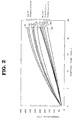
- Fig.2 shows experimental results indicating the start-up characteristics for heat rollers having different thermal conductivity.
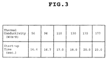
- Fig.3 shows experimental data relating to the thermal conductivity of the enclosed gas and the heating time of the metallic substrate of the roller component of the heat roller.
- a heat roller R is comprised of a cylindrical metallic substrate 1 (a hollow cylindrical metal tube) and a heating lamp 2 axially installed inside the metallic substrate 1.
- the metallic substrate 1 is made of aluminum and has an inner diameter of 30 mm.
- the heating lamp 2 has a filament 3 installed within a bulb 21 along the longitudinal axis of the bulb.
- the encapsulated gas consists of at least 99% krypton and about 1% of bromine providing a halogen incandescent lamp that is lit at 100 V and 800 W.
- the heating lamp 2 is made such that, as the enclosed gas, krypton at 99% or more and halogen at about 1% are enclosed in the bulb, and the thermal conductivity is 94 x 10 -4 (W/m ⁇ K).
- the present inventors then performed an experiment on the temperature increase of heat rollers while changing the thermal conductivity of the enclosed gas.
- the result of this experiment can be taken from Fig.2.
- Fig.2 shows a graph in which the abscissa indicates the lighting time (sec.) after the main switch of the device has been turned on and the heating lamp is lit, and the ordinate both the temperature of the bulb of the heating lamp at a specific time of lighting and the temperature of the metallic substrate of the roller section of the heat roller.
- the heat roller used in this experiment is similar to the heat roller shown in Fig.1, and only the enclosed gas of the heating lamp is changed in order to vary the thermal conductivity.
- the electric energy applied to each of the heating lamps as well as the thermal energy radiated from the filament was always the same for each of the lamps.
- the graph A1 in Fig.2 shows the bulb temperature in the case that the thermal conductivity of the enclosed gas is 177 x 10 -4 (W/m ⁇ K).
- Graph A2 shows the temperature of the metallic substrate of the roller component when the thermal conductivity of the enclosed gas is 177 x 10 -4 (W/m ⁇ K).
- the components of the enclosed gas are argon at 99% and bromine at 1%.
- the graph B1 indicates the bulb temperature when the thermal conductivity of the enclosed gas is 170 x 10 -4 (W/m ⁇ K)
- the graph B2 indicates the temperature of the metallic substrate of the roller component when the thermal conductivity of the enclosed gas is 170 x 10 -4 (W/m ⁇ K).
- the components of the enclosed gas are argon at 93%, krypton at 6% and bromine at 1%.
- the graph C1 indicates the bulb temperature when the thermal conductivity of the enclosed gas is 130 x 10 -4 (W/m ⁇ K)
- the graph C2 indicates the temperature of the metallic substrate of the roller component when the thermal conductivity of the enclosed gas is 130 x 10 -4 (W/m ⁇ K).
- the components of the enclosed gas are argon at 62%, xenon at 37% and bromine at 1%.
- the graph D1 gives the bulb temperature when the thermal conductivity of the enclosed gas is 110 x 10 -4 (W/m ⁇ K)
- the graph D2 indicates the temperature of the metallic substrate of the roller component when the thermal conductivity of the enclosed gas is 110 x 10 -4 (W/m ⁇ K).
- the components of the enclosed gas are argon at 45%, xenon at 54% and bromine at 1%.
- the graph E1 indicates the bulb temperature when the thermal conductivity of the enclosed gas is 94 x 10 -4 (W/m ⁇ K)
- the graph E2 gives the temperature of the metallic substrate of the roller component when the thermal conductivity of the enclosed gas is 94 x 10 -4 (W/m ⁇ K).
- the components of the enclosed gas in this case are krypton at 99% and bromine at 1%.
- the graph F1 indicates the bulb temperature when the thermal conductivity of the enclosed gas is 56 x 10 -4 (W/m ⁇ K)
- the graph F2 gives the temperature of the metallic substrate of the roller component when the thermal conductivity of the enclosed gas is 56 x 10 -4 (W/m ⁇ K).
- the components of the enclosed gas in this case are krypton at 99% and bromine at 1%.
- the thermal energy radiated from the filaments is the same in all of the lamps.
- Fig.3 shows the result of experiments on the thermal conductivity of the enclosed gas and the heating time of the metallic substrate acting as the roller component of the heat roller.
- the start-up time in this case is defined as the time from turning on of the heating lamp, i.e. immediately after the main switch of the device has been turned on, until the time when the temperature of the metallic substrate reaches 180 °C.
- the heat roller used in this experiment is similar to the heat roller shown in Fig.1, and only the enclosed gas in the heating lamp and its thermal conductivity are changed.
- the start-up time is as fast as 17 seconds, i.e. shorter than 18 seconds, and so this enclosed gas satisfied the requirement of speeding up the start-up time.
- the gas in which argon at 62%, xenon at 37% and bromine at 1% are present has a thermal conductivity of 130 x 10 -4 (W/m ⁇ K).
- the gas in which krypton at 99% and bromine at 1% are contained has a thermal conductivity of 94 x 10 -4 (W/m ⁇ K).
- the gas containing xenon at 99% and bromine at 1% has a thermal conductivity of 56 x 10 -4 (W/m ⁇ K).
- the rare gases that can be utilized in the encapsulated gas are krypton, xenon and argon, and the thermal conductivity of the enclosed gas can be changed by mixing these gases or using krypton or xenon as the sole rare gas.
- the argon content in the encapsulated gas is not higher than about 60% and, most preferable, not higher than about 50%.
- all the percentages given herein are volume percentages based on the total volume of the encapsulated gas.
Landscapes
- Physics & Mathematics (AREA)
- General Physics & Mathematics (AREA)
- Control Of Resistance Heating (AREA)
- Resistance Heating (AREA)
- Fixing For Electrophotography (AREA)
Applications Claiming Priority (2)
| Application Number | Priority Date | Filing Date | Title |
|---|---|---|---|
| JP35762199A JP3558161B2 (ja) | 1999-12-16 | 1999-12-16 | 加熱ローラ |
| JP35762199 | 1999-12-16 |
Publications (3)
| Publication Number | Publication Date |
|---|---|
| EP1109080A2 true EP1109080A2 (fr) | 2001-06-20 |
| EP1109080A3 EP1109080A3 (fr) | 2003-07-02 |
| EP1109080B1 EP1109080B1 (fr) | 2009-01-28 |
Family
ID=18455066
Family Applications (1)
| Application Number | Title | Priority Date | Filing Date |
|---|---|---|---|
| EP00126802A Expired - Lifetime EP1109080B1 (fr) | 1999-12-16 | 2000-12-06 | Rouleau chauffant |
Country Status (4)
| Country | Link |
|---|---|
| US (1) | US6396029B2 (fr) |
| EP (1) | EP1109080B1 (fr) |
| JP (1) | JP3558161B2 (fr) |
| DE (1) | DE60041478D1 (fr) |
Cited By (2)
| Publication number | Priority date | Publication date | Assignee | Title |
|---|---|---|---|---|
| CN110703575A (zh) * | 2012-11-21 | 2020-01-17 | 佳能株式会社 | 图像加热设备 |
| CN111480112A (zh) * | 2017-12-22 | 2020-07-31 | 卡尔斯特里姆保健公司 | 热处理滚筒 |
Families Citing this family (1)
| Publication number | Priority date | Publication date | Assignee | Title |
|---|---|---|---|---|
| US6559421B1 (en) * | 1999-10-29 | 2003-05-06 | Ricoh Company, Ltd. | Image forming apparatus and fixing device therefor |
Citations (1)
| Publication number | Priority date | Publication date | Assignee | Title |
|---|---|---|---|---|
| JPH07230795A (ja) | 1994-02-16 | 1995-08-29 | Toshiba Lighting & Technol Corp | 発熱用ハロゲン電球、加熱装置および画像形成装置 |
Family Cites Families (8)
| Publication number | Priority date | Publication date | Assignee | Title |
|---|---|---|---|---|
| US3974413A (en) * | 1975-05-01 | 1976-08-10 | General Motors Corporation | Incandescent lamp with modified helium fill gas |
| US4591752A (en) * | 1983-10-14 | 1986-05-27 | Duro-Test Corporation | Incandescent lamp with high pressure rare gas filled tungsten-halogen element and transparent thick walled safety envelope |
| US4598342A (en) * | 1984-07-09 | 1986-07-01 | Gte Products Corporation | Low wattage double filament tungsten-halogen lamp |
| JPS61204666A (ja) * | 1985-03-08 | 1986-09-10 | Fuji Xerox Co Ltd | 熱ロ−ル定着装置 |
| DE3621195A1 (de) * | 1985-06-26 | 1987-01-29 | Stanley Electric Co Ltd | Hochleistungsgluehlampe |
| JP2542080B2 (ja) * | 1989-06-23 | 1996-10-09 | キヤノン株式会社 | 熱ロ―ラ定着装置 |
| JPH03107978A (ja) * | 1989-09-22 | 1991-05-08 | Tonen Corp | 定着用ローラ |
| JP2857137B1 (ja) * | 1997-12-25 | 1999-02-10 | ウシオ電機株式会社 | ショートアーク型水銀ランプ |
-
1999
- 1999-12-16 JP JP35762199A patent/JP3558161B2/ja not_active Expired - Lifetime
-
2000
- 2000-12-06 DE DE60041478T patent/DE60041478D1/de not_active Expired - Lifetime
- 2000-12-06 EP EP00126802A patent/EP1109080B1/fr not_active Expired - Lifetime
- 2000-12-15 US US09/736,289 patent/US6396029B2/en not_active Expired - Lifetime
Patent Citations (1)
| Publication number | Priority date | Publication date | Assignee | Title |
|---|---|---|---|---|
| JPH07230795A (ja) | 1994-02-16 | 1995-08-29 | Toshiba Lighting & Technol Corp | 発熱用ハロゲン電球、加熱装置および画像形成装置 |
Cited By (2)
| Publication number | Priority date | Publication date | Assignee | Title |
|---|---|---|---|---|
| CN110703575A (zh) * | 2012-11-21 | 2020-01-17 | 佳能株式会社 | 图像加热设备 |
| CN111480112A (zh) * | 2017-12-22 | 2020-07-31 | 卡尔斯特里姆保健公司 | 热处理滚筒 |
Also Published As
| Publication number | Publication date |
|---|---|
| US6396029B2 (en) | 2002-05-28 |
| JP3558161B2 (ja) | 2004-08-25 |
| EP1109080B1 (fr) | 2009-01-28 |
| US20010004072A1 (en) | 2001-06-21 |
| EP1109080A3 (fr) | 2003-07-02 |
| JP2001176641A (ja) | 2001-06-29 |
| DE60041478D1 (de) | 2009-03-19 |
Similar Documents
| Publication | Publication Date | Title |
|---|---|---|
| CA2042258C (fr) | Lampe hid sans electrode a connecteur hyperfrequences | |
| US5113121A (en) | Electrodeless HID lamp with lamp capsule | |
| US6646227B2 (en) | Image forming apparatus and fixing device therefor | |
| US5598069A (en) | Amalgam system for electrodeless discharge lamp | |
| US5274305A (en) | Low pressure mercury discharge lamp with thermostatic control of mercury vapor pressure | |
| US6737809B2 (en) | Plasma lamp with dielectric waveguide | |
| EP0663139B1 (fr) | Lampe sans electrodes a ampoule tournante | |
| EP0457242B1 (fr) | Lampe de décharge à haute intensité sans électrode avec coupleur à raccorder à un générateur à micro-ondes | |
| US6396029B2 (en) | Heat roller | |
| US3973155A (en) | Incandescent source of visible radiations | |
| JPH08274067A (ja) | プラズマ発生装置 | |
| US6911625B2 (en) | Heating roller | |
| TW511115B (en) | Mercury lamp of the short arc type and UV emission device | |
| JP2000057994A (ja) | ダブルエンド型低電力メタルハライドランプ | |
| US4797598A (en) | Illumination apparatus | |
| JP3993985B2 (ja) | ヒータ、加熱ローラ、定着装置及び画像形成装置 | |
| JP2003217803A (ja) | ヒータランプ | |
| JP3668149B2 (ja) | 定着装置 | |
| JPS5810360A (ja) | 温度制御金属蒸気放電灯 | |
| EP0704881A2 (fr) | Lampe à décharge | |
| JPS61126760A (ja) | 照明装置 | |
| JP2007058231A (ja) | 定着装置・画像形成装置 | |
| JP2712719B2 (ja) | 熱陰極型希ガス放電蛍光ランプ装置 | |
| JPH0620601A (ja) | 放電ランプにおける水銀の封入方法 | |
| JP2004206136A (ja) | 定着装置・画像形成装置 |
Legal Events
| Date | Code | Title | Description |
|---|---|---|---|
| PUAI | Public reference made under article 153(3) epc to a published international application that has entered the european phase |
Free format text: ORIGINAL CODE: 0009012 |
|
| AK | Designated contracting states |
Kind code of ref document: A2 Designated state(s): AT BE CH CY DE DK ES FI FR GB GR IE IT LI LU MC NL PT SE TR |
|
| AX | Request for extension of the european patent |
Free format text: AL;LT;LV;MK;RO;SI |
|
| PUAL | Search report despatched |
Free format text: ORIGINAL CODE: 0009013 |
|
| RIC1 | Information provided on ipc code assigned before grant |
Ipc: 7G 03G 15/20 A Ipc: 7H 01K 1/50 B Ipc: 7H 05B 3/00 B |
|
| AK | Designated contracting states |
Designated state(s): AT BE CH CY DE DK ES FI FR GB GR IE IT LI LU MC NL PT SE TR |
|
| AX | Request for extension of the european patent |
Extension state: AL LT LV MK RO SI |
|
| 17P | Request for examination filed |
Effective date: 20030710 |
|
| AKX | Designation fees paid |
Designated state(s): DE GB NL |
|
| 17Q | First examination report despatched |
Effective date: 20060821 |
|
| GRAP | Despatch of communication of intention to grant a patent |
Free format text: ORIGINAL CODE: EPIDOSNIGR1 |
|
| GRAS | Grant fee paid |
Free format text: ORIGINAL CODE: EPIDOSNIGR3 |
|
| GRAA | (expected) grant |
Free format text: ORIGINAL CODE: 0009210 |
|
| AK | Designated contracting states |
Kind code of ref document: B1 Designated state(s): DE GB NL |
|
| REG | Reference to a national code |
Ref country code: GB Ref legal event code: FG4D |
|
| REF | Corresponds to: |
Ref document number: 60041478 Country of ref document: DE Date of ref document: 20090319 Kind code of ref document: P |
|
| PLBE | No opposition filed within time limit |
Free format text: ORIGINAL CODE: 0009261 |
|
| STAA | Information on the status of an ep patent application or granted ep patent |
Free format text: STATUS: NO OPPOSITION FILED WITHIN TIME LIMIT |
|
| 26N | No opposition filed |
Effective date: 20091029 |
|
| PGFP | Annual fee paid to national office [announced via postgrant information from national office to epo] |
Ref country code: NL Payment date: 20191114 Year of fee payment: 20 Ref country code: DE Payment date: 20191126 Year of fee payment: 20 |
|
| PGFP | Annual fee paid to national office [announced via postgrant information from national office to epo] |
Ref country code: GB Payment date: 20191206 Year of fee payment: 20 |
|
| REG | Reference to a national code |
Ref country code: DE Ref legal event code: R071 Ref document number: 60041478 Country of ref document: DE |
|
| REG | Reference to a national code |
Ref country code: NL Ref legal event code: MK Effective date: 20201205 |
|
| REG | Reference to a national code |
Ref country code: GB Ref legal event code: PE20 Expiry date: 20201205 |
|
| PG25 | Lapsed in a contracting state [announced via postgrant information from national office to epo] |
Ref country code: GB Free format text: LAPSE BECAUSE OF EXPIRATION OF PROTECTION Effective date: 20201205 |