EP1109260A1 - Anordnung zur federnden Kontaktierung für Fahrzeug - Google Patents
Anordnung zur federnden Kontaktierung für Fahrzeug Download PDFInfo
- Publication number
- EP1109260A1 EP1109260A1 EP00403487A EP00403487A EP1109260A1 EP 1109260 A1 EP1109260 A1 EP 1109260A1 EP 00403487 A EP00403487 A EP 00403487A EP 00403487 A EP00403487 A EP 00403487A EP 1109260 A1 EP1109260 A1 EP 1109260A1
- Authority
- EP
- European Patent Office
- Prior art keywords
- section
- blade
- movable
- maintained
- orifice
- Prior art date
- Legal status (The legal status is an assumption and is not a legal conclusion. Google has not performed a legal analysis and makes no representation as to the accuracy of the status listed.)
- Withdrawn
Links
- 238000005452 bending Methods 0.000 claims description 5
- 230000000694 effects Effects 0.000 claims description 2
- BASFCYQUMIYNBI-UHFFFAOYSA-N platinum Chemical compound [Pt] BASFCYQUMIYNBI-UHFFFAOYSA-N 0.000 description 7
- 230000000295 complement effect Effects 0.000 description 2
- 239000004020 conductor Substances 0.000 description 2
- 238000003780 insertion Methods 0.000 description 2
- 230000037431 insertion Effects 0.000 description 2
- 229910052751 metal Inorganic materials 0.000 description 2
- 239000002184 metal Substances 0.000 description 2
- 238000000034 method Methods 0.000 description 2
- 229910052697 platinum Inorganic materials 0.000 description 2
- 210000002105 tongue Anatomy 0.000 description 2
- 238000006243 chemical reaction Methods 0.000 description 1
- 238000002788 crimping Methods 0.000 description 1
- 238000006073 displacement reaction Methods 0.000 description 1
- 238000009434 installation Methods 0.000 description 1
- 238000004519 manufacturing process Methods 0.000 description 1
- 239000000463 material Substances 0.000 description 1
- 238000000465 moulding Methods 0.000 description 1
- 238000004806 packaging method and process Methods 0.000 description 1
- 230000002787 reinforcement Effects 0.000 description 1
- 230000000284 resting effect Effects 0.000 description 1
- 230000000630 rising effect Effects 0.000 description 1
- 238000002604 ultrasonography Methods 0.000 description 1
Images



Classifications
-
- H—ELECTRICITY
- H01—ELECTRIC ELEMENTS
- H01R—ELECTRICALLY-CONDUCTIVE CONNECTIONS; STRUCTURAL ASSOCIATIONS OF A PLURALITY OF MUTUALLY-INSULATED ELECTRICAL CONNECTING ELEMENTS; COUPLING DEVICES; CURRENT COLLECTORS
- H01R13/00—Details of coupling devices of the kinds covered by groups H01R12/70 or H01R24/00 - H01R33/00
- H01R13/02—Contact members
- H01R13/28—Contacts for sliding cooperation with identically-shaped contact, e.g. for hermaphroditic coupling devices
-
- H—ELECTRICITY
- H01—ELECTRIC ELEMENTS
- H01R—ELECTRICALLY-CONDUCTIVE CONNECTIONS; STRUCTURAL ASSOCIATIONS OF A PLURALITY OF MUTUALLY-INSULATED ELECTRICAL CONNECTING ELEMENTS; COUPLING DEVICES; CURRENT COLLECTORS
- H01R2201/00—Connectors or connections adapted for particular applications
- H01R2201/26—Connectors or connections adapted for particular applications for vehicles
Definitions
- the present invention relates to the field of connectors electric.
- the present invention applies to the steering wheel switch, for motor vehicle. It aims to offer new means for connecting a switching device such as than a lever switch, to a fixed plate linked to the top of the column.
- the object of the present invention is in particular to propose means capable of absorbing positioning faults between two sets to connect. Another object of the invention is to propose inexpensive means of connection.
- the present invention also relates to an assembly for top of column comprising at least one switch, one plate, and one connection device of the aforementioned type able to connect the switch and the platinum.
- a lever switch for be positioned on the side of a switch plate under the steering wheel, top of a motor vehicle column. It basically consists a housing 10 and a control arm or lever 20 mounted on the housing with multiple freedom of movement (pivoting of the lever in two axes orthogonal to each other and transverse to the longitudinal axis of the lever; rotational movement on itself around its longitudinal axis, or even translation along this longitudinal axis), each movement corresponding to a particular switching of the electrical system (projectors, direction change alert, windscreen wiper / washer, etc.) thanks to electrical switching means known in themselves, placed in the housing 10 and controlled by the lever 20.
- the housing 10 contains a series of conductors electrics associated with switches each controlled by a specific movement of the arm 10. These conductors each terminate by a contact emerging on the outside of the housing 10 to contact a corresponding track of the turntable.
- These contacts are here constituted by metal blades 100 which emerge in an oblique position relative to the upper face 14 of the housing 10, and having a free end intended to approach elastically from the upper face 14 when the blade 100 is put in contact on the board.
- the housing 10 has a series of such blades 100, placed at vicinity of an edge of the upper face 14, perpendicular to this edge and parallel to each other.
- each of these blades will be described below, which are, in the present exemplary embodiment, implemented simultaneously on the housing 10.
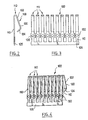
- the blades 100 are, in a first step, supplied in a single block as a single piece. They are for that cut from the same metal sheet, without being separated initially between them.
- the blades 100 are presented initially ( Figures 2 to 4) in the form of a rack with branches (blades) are linked together by a transverse segment 105 forming an integral part with the end of each of them.
- Each blade has two sections, the first 110 adjacent to segment 105 and intended to be fixed against the housing 10, and the second 120 forming a free arm to be flexed elastically towards the first section.
- the two sections 110 and 120 here form the branches of a U.
- the folding zone between the two sections 110, 120 is referenced 112 in Figures 2 to 4.
- the fixed section 110 is straight for a bearing on the case by almost all its length while the movable section 120 itself consists of two segments 122, 124 inclined to one another, concave towards the segment 110, and thus curved towards the center of the U, to present, towards the outside, an elbow convex rounded without risk of abutment or snagging.
- the U formed here also has a longer arm than the other, in that the fixed section 110 is longer than the movable arm 120.
- the part of the section 110 which emerges beyond the arm 120 carries means hooking on the housing 10, so that the fixing of the section 110 on the housing is not hampered by the presence of the movable section 120.
- the blade 100 has a constant width and thickness except in the center of this emerging part of the fixed section, where it widens in a square-shaped reinforcement, at the center of which is an orifice 130 intended to secure the blades 100 on the housing 10.
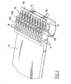
- This series of blades 100 is placed on a part 14 forming a cover upper case 10 ( Figure 5).
- the upper face of the cover 14 forms a series of 16 elongated, parallel housings, placed one behind the others along an edge 13 of the cover 14.
- Each housing 16 has a closed end towards the inside of the cover 14 and one end open towards the edge 13 of the cover.
- each housing is formed by low walls elevation on the upper face of the cover 14, that is to say two low walls side 17 shared with neighboring dwellings, and a low wall.
- Each lateral wall 17 has a length slightly greater than the length of the movable arm 120.
- the fixed section 110 of the blade 100 is placed in the bottom of the housing 16, the fixed section 110 covering the lower wall of the housing 16 and the movable arm 120 rising above the walls 17 only by its part contact cubit corresponding to the connection area between the two segments 122, 124.
- the free end of the movable arm 120 remains in particular between the walls 17, to avoid any risk of accidental catching of the arm 120.
- Track 18 carries a molding cylinder on the cover 14, a vertical pin 19 of plastic material opposite each housing 16, which is placed in an orifice 130 respectively associated.
- these pins 19 are crushed, for example by ultrasound, at their end emerging from the orifice 130 and are deformed against the periphery of the orifice, thus forming a crimping like a rivet.
- the blade 100 exceeds the edge 13, maintaining the transverse link 105 of the free blade rack beyond the cover 14.
- the transverse link 105 is then separated from the blades 100 by cut out flush with its edge on the blade side.
- each blade 100 which protrudes from the edge 13 is then folded down and then welded with a link carried in the housing 10.
- a disposable packaging is provided fixed so that removable on the cover 14 to protect fragile areas including the blades.
- the housing 10 is designed to be introduced into a cavity complementary to a plate 200.
- the cover 14 is configured to that the edge 13 carrying the blades 100 is the edge closest to the arm of control 20, the blades 100 having their free end in the same direction than arm 20.
- the blades 100 slide without risk of snagging against tracks of an internal face of the plate 200, adapting by elasticity against these tracks.
- the internal face of the plate 200 on which slide the blades 100 is constituted by an electronic card, spaced about 5 mm from the upper face of the housing 10, to be able to accommodate electronic components outside the friction zones.
- Blades 100 having such a geometry and such a method of fixing are very reliable in that they do not suffer from vehicle vibrations or deviations from parts tolerances. These assets are obtained without making no costly or bulky items required, and the number of links is easily multiplied without significant additional production cost.
- the housing 10 carries two tongues 15 which run along two opposite sides of the housing, flexible closer to the housing and each carrying an external lug intended for lean against a shoulder formed in the complementary cavity of platinum.
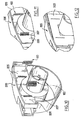
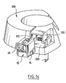
- FIGS. 5 to 14 An alternative embodiment has been presented in FIGS. 5 to 14 in which a series of blades 100 is mounted not on a housing of arm switch, but on a turntable 200.
- the plate 200 has a receiving cavity, one wall of which lateral 205, lower side of the plate, is provided with a series of orifices through 207 each intended to receive a blade 100 from the face bottom of this wall 205.
- This series of orifices 207 extends in line along a border connecting this lower side wall 205 to a wall 210 forming the bottom of the cavity. Each blade 100 passing through an orifice 207 then runs along a part of this bottom wall 210, transversely to the direction of insertion of the housing 10.
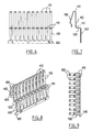
- each blade 100 has here again a first substantially fixed section 110, and a second section 120 flexible, closer to the first.
- the blade 100 thus has a U-shaped part, including a branch is formed by the fixed section 110, rectilinear and positioned in covering the bottom wall 210, and of which the other branch is formed by the movable section 120, which covers part of the fixed section 110.
- the movable section 120 is seen pushed back in elastic bending towards the bottom 210 of the cavity by a contact carried by the housing 10.
- the profile of the present blades 100 differs from that of the previous, in that the fixed portion 110 partially has a direction different from that of the movable portion 120.
- the fixed section 110 extends, preferably but not necessarily, in a slightly oblique general direction by compared to the movable section 120, it has a segment 115 which forks abruptly perpendicular to the covering part of a fixed section 110 and this away from the mobile section 120.
- This segment 115 therefore constitutes a right-angle fold, intended for come into abutment against an edge of the orifice 207 receiving the blade, opposite bottom of the wall 205.
- the segment 115 has an outline substantially square.
- This fold 115 further carries an orifice 130 intended to receive a pin 19 formed by the wall 205, subsequently crimped on the edges of the orifice 130, as described above.
- the present blade 100 forms, beyond this segment 115, a new right angle to a third segment 140, straight, and parallel to the direction of the section 110, away from the latter.
- the present blades 100 form a segment intermediate 115 folded at right angles to two straight portions 110 and 140 which extend on either side of this segment 115.
- the end of the third section 140 joins a segment transverse 105 of junction between the blades, forming before this junction 105 a first part of reduced width, preceded by a shoulder, and, beyond this first part of reduced width, a second part of width still reduced, weakened by a subsequent detachment of the junction transverse 105.
- the series of blades 100 is placed in the orifices 207, the U formed by each blade being introduced, bottom 112 in first, in a corresponding orifice 207.
- the blades being linked between them, this implementation step is particularly easy.
- each segment 115 then abuts against the face bottom of wall 205, a pin 19 formed by this wall being placed in each orifice 130. Then each pin 19 is crimped.
- the orifice 207 is then crossed by both the straight section 110 and by an end portion of the movable part 120, this portion end being free of transverse movement in the orifice 207. Recalled in spacing from the fixed portion 110, the movable portion 120 comes resting against an opposite edge of the orifice 207.
- This part of the movable branch 120 which is present in the orifice 207 is here constituted by a rectilinear segment, parallel to the section 110, formed beyond an elbow part rounded towards the outside of the section 120.
- connection transverse 105 is separated from the blades, which then point by their section 140 towards the bottom of the plate 200.
- An electronic card 300 is then engaged under the plate, and the blades 100 come, by their part of restricted width, to engage in corresponding holes in the card 300.
- the series of blades 100 is contacted by studs distributed on a lower edge front of the housing 10.
- the receiving cavity of the plate 200 comprises two opposite faces, each with a border cutout exterior for manual access to the mounting tongues 15 of the housing 10.
- a third variant of the invention in which the blade 100 again exhibits part of U-shaped contacting, one branch 120 of which is mobile in bending towards the other branch 110 and in which blade a central fixing part 115 forms a segment perpendicular to these branches 110 and 120.
- the U-shaped part is introduced at through a lower wall 205 of the plate.
- the blade 100 extends beyond the fixing point 115 by a portion 150 flexible elastically. Once the blades 100 are fixed on the plate, they come to contact a series of contact leads from a printed card 300 carried by the plate, by simple elastic support.
- This second flexible portion 150 extends for this from the pin 19 for fixing, deviating laterally from a face carrying this pin, forming an inflection point to present on either side of this point of bending two end portions substantially parallel to the wall 205 and to the printed card 300.
- the free end of this portion 150 is furthermore slightly curved, thus presenting a rounded convex part towards the menu.
- the card 300 is thus easily connected to the card, without plugging.
Landscapes
- Coupling Device And Connection With Printed Circuit (AREA)
Applications Claiming Priority (2)
| Application Number | Priority Date | Filing Date | Title |
|---|---|---|---|
| FR9915738A FR2802348B1 (fr) | 1999-12-14 | 1999-12-14 | Connecteur a lames flexibles pour vehicule automobile |
| FR9915738 | 1999-12-14 |
Publications (1)
| Publication Number | Publication Date |
|---|---|
| EP1109260A1 true EP1109260A1 (de) | 2001-06-20 |
Family
ID=9553226
Family Applications (1)
| Application Number | Title | Priority Date | Filing Date |
|---|---|---|---|
| EP00403487A Withdrawn EP1109260A1 (de) | 1999-12-14 | 2000-12-12 | Anordnung zur federnden Kontaktierung für Fahrzeug |
Country Status (2)
| Country | Link |
|---|---|
| EP (1) | EP1109260A1 (de) |
| FR (1) | FR2802348B1 (de) |
Citations (5)
| Publication number | Priority date | Publication date | Assignee | Title |
|---|---|---|---|---|
| DE2721776A1 (de) * | 1977-05-13 | 1978-11-16 | Siemens Ag | Mehrfachsteckvorrichtung mit im wesentlichen identisch aufgebauten steckvorrichtungshaelften |
| US4582376A (en) * | 1984-04-09 | 1986-04-15 | Amp Incorporated | Shorting bar having wiping action |
| US5588844A (en) * | 1994-11-21 | 1996-12-31 | The Whitaker Corporation | Variable orientation, surface mounted connector |
| US5599192A (en) * | 1993-02-22 | 1997-02-04 | Berg Technology, Inc. | Blade-like terminal having a passive latch |
| DE19653932C1 (de) * | 1996-12-21 | 1998-03-26 | Kostal Leopold Gmbh & Co Kg | Vorrichtung zur Übertragung von Signalen |
-
1999
- 1999-12-14 FR FR9915738A patent/FR2802348B1/fr not_active Expired - Fee Related
-
2000
- 2000-12-12 EP EP00403487A patent/EP1109260A1/de not_active Withdrawn
Patent Citations (5)
| Publication number | Priority date | Publication date | Assignee | Title |
|---|---|---|---|---|
| DE2721776A1 (de) * | 1977-05-13 | 1978-11-16 | Siemens Ag | Mehrfachsteckvorrichtung mit im wesentlichen identisch aufgebauten steckvorrichtungshaelften |
| US4582376A (en) * | 1984-04-09 | 1986-04-15 | Amp Incorporated | Shorting bar having wiping action |
| US5599192A (en) * | 1993-02-22 | 1997-02-04 | Berg Technology, Inc. | Blade-like terminal having a passive latch |
| US5588844A (en) * | 1994-11-21 | 1996-12-31 | The Whitaker Corporation | Variable orientation, surface mounted connector |
| DE19653932C1 (de) * | 1996-12-21 | 1998-03-26 | Kostal Leopold Gmbh & Co Kg | Vorrichtung zur Übertragung von Signalen |
Also Published As
| Publication number | Publication date |
|---|---|
| FR2802348A1 (fr) | 2001-06-15 |
| FR2802348B1 (fr) | 2002-03-01 |
Similar Documents
| Publication | Publication Date | Title |
|---|---|---|
| EP2150444B1 (de) | Mit adapter interagierende anschlussbasis zur bildung eines mechanischen verbinders für das wischblatt eines fahrzeuges | |
| FR2720197A1 (fr) | Connecteur pour câble électrique. | |
| FR2786613A1 (fr) | Dispositif pour raccorder un cable coaxial a une carte de circuit imprime | |
| EP0766875B1 (de) | Elektrischer verbinder insbesondere für den anschluss einer elektronischen speicherkarte | |
| FR2968256A1 (fr) | Connecteur hydraulique pour balai d'essuie-glace a bouton escamotable | |
| EP0643446A1 (de) | Verbesserungen an Gehäusen von elektrischen Verbindern | |
| EP2456021B1 (de) | Stromsteckdose mit seitlichen verschiebbaren Balken | |
| EP1588459A1 (de) | Mit druckkontaktanschlüssen ausgestattetersteckverbinder | |
| FR2755790A1 (fr) | Commutateur a bouton-poussoir miniature, notamment pour une unite de disque souple | |
| EP1135833B1 (de) | Bauweise für den automatisierten anschluss von zwei elektronischen stromkreisen eines kraftfahrzeugs | |
| EP2745661B1 (de) | Elektrische verbindungsvorrichtung, anordnung mit einer solchen vorrichtung und elektronikplatine sowie verfahren zum elektrischen anschluss einer elektronikplatine | |
| FR2844695A1 (fr) | Appareil electromenager a panneaux articules | |
| EP3790126B1 (de) | Einheit für steckverbinder, die für eine blindmontage geeignet ist | |
| FR2802348A1 (fr) | Connecteur a lames flexibles pour vehicule automobile | |
| EP0987793B1 (de) | Elektrischer Verbinder mit geringer Einsteckkraft insbesondere mit Kontaktmesser für flexible Schaltung | |
| EP0560648B1 (de) | Polygonal Steckverbinder, insbesondere viereckig mit einem isolierenden Zentralkörper | |
| EP0685911A1 (de) | Koaxial elektrische Verbindungselement zur Erzeugung einer Schaltung elektrische Verbindung beinhalten eines solches Verbindungselementes | |
| EP0994529A1 (de) | Elektrischer Steckverbinder mit geringer Einsteck- und Herausziehkraft und C-förmigen Kontakten und Messerkontakten | |
| FR2857511A1 (fr) | Borne de raccordement a obturateur de guidage rappele | |
| FR2862784A1 (fr) | Dispositif pour le raccordement electrique d'une carte a puce | |
| FR2748977A1 (fr) | Motoreducteur pour essuie-glace et organe de connexion associe | |
| EP3805502B1 (de) | Zentriervorrichtung für eine schiebetür | |
| FR2784260A1 (fr) | Contacts sans soudure entre des pistes decoupees et un circuit imprime | |
| EP1908967A1 (de) | Vorrichtung zum Befestigen eines Kabels auf einer Halteplatine | |
| FR2843496A1 (fr) | Bloc de jonction electrique a fenetre autobloquante |
Legal Events
| Date | Code | Title | Description |
|---|---|---|---|
| PUAI | Public reference made under article 153(3) epc to a published international application that has entered the european phase |
Free format text: ORIGINAL CODE: 0009012 |
|
| AK | Designated contracting states |
Kind code of ref document: A1 Designated state(s): DE ES GB IT |
|
| AX | Request for extension of the european patent |
Free format text: AL;LT;LV;MK;RO;SI |
|
| 17P | Request for examination filed |
Effective date: 20011203 |
|
| AKX | Designation fees paid |
Free format text: DE ES GB IT |
|
| STAA | Information on the status of an ep patent application or granted ep patent |
Free format text: STATUS: THE APPLICATION IS DEEMED TO BE WITHDRAWN |
|
| 18D | Application deemed to be withdrawn |
Effective date: 20050701 |