EP1109277A2 - Elément d'accouplement de deux appareils électriques montés côte-à-côte, et méthode d'accouplement d'appareillages électriques - Google Patents
Elément d'accouplement de deux appareils électriques montés côte-à-côte, et méthode d'accouplement d'appareillages électriques Download PDFInfo
- Publication number
- EP1109277A2 EP1109277A2 EP00126173A EP00126173A EP1109277A2 EP 1109277 A2 EP1109277 A2 EP 1109277A2 EP 00126173 A EP00126173 A EP 00126173A EP 00126173 A EP00126173 A EP 00126173A EP 1109277 A2 EP1109277 A2 EP 1109277A2
- Authority
- EP
- European Patent Office
- Prior art keywords
- connecting element
- base body
- installation
- element according
- recesses
- Prior art date
- Legal status (The legal status is an assumption and is not a legal conclusion. Google has not performed a legal analysis and makes no representation as to the accuracy of the status listed.)
- Granted
Links
Images

Classifications
-
- H—ELECTRICITY
- H02—GENERATION; CONVERSION OR DISTRIBUTION OF ELECTRIC POWER
- H02B—BOARDS, SUBSTATIONS OR SWITCHING ARRANGEMENTS FOR THE SUPPLY OR DISTRIBUTION OF ELECTRIC POWER
- H02B1/00—Frameworks, boards, panels, desks, casings; Details of substations or switching arrangements
- H02B1/015—Boards, panels, desks; Parts thereof or accessories therefor
- H02B1/04—Mounting thereon of switches or of other devices in general, the switch or device having, or being without, casing
-
- H—ELECTRICITY
- H01—ELECTRIC ELEMENTS
- H01H—ELECTRIC SWITCHES; RELAYS; SELECTORS; EMERGENCY PROTECTIVE DEVICES
- H01H71/00—Details of the protective switches or relays covered by groups H01H73/00 - H01H83/00
- H01H71/02—Housings; Casings; Bases; Mountings
- H01H71/0264—Mountings or coverplates for complete assembled circuit breakers, e.g. snap mounting in panel
- H01H71/0271—Mounting several complete assembled circuit breakers together
-
- H—ELECTRICITY
- H02—GENERATION; CONVERSION OR DISTRIBUTION OF ELECTRIC POWER
- H02B—BOARDS, SUBSTATIONS OR SWITCHING ARRANGEMENTS FOR THE SUPPLY OR DISTRIBUTION OF ELECTRIC POWER
- H02B1/00—Frameworks, boards, panels, desks, casings; Details of substations or switching arrangements
- H02B1/015—Boards, panels, desks; Parts thereof or accessories therefor
- H02B1/04—Mounting thereon of switches or of other devices in general, the switch or device having, or being without, casing
- H02B1/041—Mechanical coupling for side-by-side mounted apparatus
Definitions
- the invention relates to a connecting element according to the preamble of the claim 1, and a method according to the preamble of claim 7.
- a single-pole electrical circuit breaker has a shell-shaped housing is formed, the end edges of the shell walls placed against each other become; the two shells are fixed to each other by means of riveted connections.
- Such single-pole circuit breakers can be assembled into multi-pole become. It is known to rivet the individual poles together.
- Such riveted joints are technically complex, because they have warehousing on the one hand condition for the rivets and, on the other hand, an operation is to be provided with which the riveting is carried out.
- the object of the invention is to provide a connecting element of the type mentioned create, in which the connection process of two installation devices to be connected is simplified.
- the connecting element has an approximately cylindrical base body with a first outer diameter on which two radially spring-loaded axially projecting spreader arms are formed, whose radial outer contour represents a cylindrical surface and its free end on opposite lying surface lines have radially projecting lugs, which in the assembled Condition behind recesses on the housings to be connected to the connecting part the installation devices.
- the connecting element a sleeve shape, which has an axial longitudinal slot, the middle between the two Surface lines is arranged.
- the base body is also resilient, so that it serves to center the adjacent installation devices.
- the spreading arms on one Side separated are adapted diametrically to form the spreading arms compared to the longitudinal slot in the area of the expansion arms introduced more slots.
- the free ends of the Arms tapered with the noses, so that the diameter of the sleeve shape the ends is smaller than the diameter in the area of the noses.
- the transition surface is the Base body to the spreader arms and the transition surface from the spreader arms to each of the noses is conical, the cone angle being slightly smaller than Is 180 °.
- the connecting element between the two housings can be provided for fixing a pin that can be inserted into the interior of the sleeve shape his.
- the pin prevents the longitudinal edges of the longitudinal slot from springing apart or the spreading arms. If e.g. B. an auxiliary switch on a switching device such a spigot is usually not required. In the end there is a cone then not necessary if the elasticity of the connecting element is not great, d. H. the connecting element is relatively rigid.
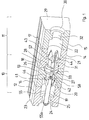
- FIG. 1 shows a partial sectional view of two housings 10 and 12 arranged next to one another 11 of an installation switching device, wherein each housing 10, 11 from two shell-shaped Housing parts 12, 13 and 14, 15 is assembled, the dividing line between the housing parts 12 and 13, the reference number 16 and the parting line between the housing parts 14 and 15 bear the reference number 17.
- the touch area the two housings 10, 11 are designated 18.
- each housing part has a cylindrical recess 19, 20 and 21, 22 which, when assembled, when the two housing parts 12, 13 or 14, 15 are placed together, a cylindrical one Form interior.
- the broad side of the housing part 13 has the parting line or contact surface 18 forms a recess 26 opening into this surface, which with the recess 20 is connected through a through hole 27.
- a connecting element 33 is inserted into these recesses or through holes, that is shown in Fig. 2 in section.
- the connecting element 33 has a central cylindrical body 34, from the end faces 35 and 36 projecting in the axial direction resilient Spreading arms 37, 38, 39 and 40.
- the outer diameter of the base body 34 is selected so that it fits into the recesses 26, 28.
- the enveloping arms 37 to 40 Cylinder surface has an outer diameter that is the inner diameter of the through holes 25, 27, 31 and 32 corresponds.
- the lugs 41, 42, 43 and 44 have an outer surface, which forms a conical shape or a truncated cone, the truncated cones forming taper towards the free ends of the spreader arms 37, 38, 39 and 40.
- the spreading arms 37, 38, 39 and 40 and the base body 34 are of a longitudinal bore 45 penetrated so that there is a sleeve shape for the connecting element results.
- This sleeve shape has a longitudinal slot 46, and together with the slots 47 and 48, which protrude approximately into the direction of the base body 34 the resilient spreading arms 37 to 40 are formed.
- the lugs 41 to 44 have on their end faces 35 and 36 opposite Surfaces 49 and 50 also have a conical shape which is open towards the free end and also has a similar opening angle as the end faces 35 and 36.
- Fig. 2 shows like the Fig. 1- that the slots 47 and 48 and the longitudinal slot 46 has an extension 51, 52, 53 and 54 in the region of the noses.
- This Extensions serve to insert a pin 55 into the through hole 56, which prevents the sleeve shape of the connecting element from springing inwards yields in which the opposite edges of the longitudinal slot spring towards each other.
- the pin 55 is a locking element.
- the two housing parts 12, 13 and 14, 15 are first assembled to an installation device 10 or 11 respectively. Then the connecting element with the spreading arms 39, 40 inserted through the through opening 31; as soon as they have slid through the through opening 31, reach behind the recess 57 adjoining the through opening.
- the pin 55 has a circumferential thickening 55a at its free ends, 55b, through which tolerances can also be compensated here.
- the interior of the shell need not be circular cylindrical; the interior can too be delimited by two roughly parallel walls.
- the circular cylinder shape is preferred used when there is a possibility that the pin can be inserted got to. For storage reasons, the circular cylinder shape makes sense, since then only one Kind of a connecting element can be kept in stock.
Landscapes
- Power Engineering (AREA)
- Engineering & Computer Science (AREA)
- Details Of Connecting Devices For Male And Female Coupling (AREA)
- Snaps, Bayonet Connections, Set Pins, And Snap Rings (AREA)
- Coupling Device And Connection With Printed Circuit (AREA)
- Joining Of Building Structures In Genera (AREA)
- Distribution Board (AREA)
- Switch Cases, Indication, And Locking (AREA)
- Dowels (AREA)
- Handcart (AREA)
- Transformers For Measuring Instruments (AREA)
- Fuses (AREA)
- Breakers (AREA)
Applications Claiming Priority (2)
| Application Number | Priority Date | Filing Date | Title |
|---|---|---|---|
| DE19961242A DE19961242B4 (de) | 1999-12-18 | 1999-12-18 | Verbindungselement für zwei nebeneinander angereihte, mit ihren Breitseiten aneinanderliegende Installationsgeräte, und Verfahren zur Verbindung der Installationsgeräte |
| DE19961242 | 1999-12-18 |
Publications (3)
| Publication Number | Publication Date |
|---|---|
| EP1109277A2 true EP1109277A2 (fr) | 2001-06-20 |
| EP1109277A3 EP1109277A3 (fr) | 2002-04-10 |
| EP1109277B1 EP1109277B1 (fr) | 2011-06-29 |
Family
ID=7933272
Family Applications (1)
| Application Number | Title | Priority Date | Filing Date |
|---|---|---|---|
| EP00126173A Expired - Lifetime EP1109277B1 (fr) | 1999-12-18 | 2000-11-30 | Elément d'accouplement de deux appareils électriques montés côte-à-côte, et méthode d'accouplement d'appareillages électriques |
Country Status (10)
| Country | Link |
|---|---|
| US (1) | US6485329B2 (fr) |
| EP (1) | EP1109277B1 (fr) |
| CN (1) | CN1308397A (fr) |
| AT (1) | ATE515085T1 (fr) |
| CA (1) | CA2328667A1 (fr) |
| DE (1) | DE19961242B4 (fr) |
| HU (1) | HUP0004895A3 (fr) |
| NO (1) | NO20006367L (fr) |
| PL (1) | PL344637A1 (fr) |
| SG (1) | SG92766A1 (fr) |
Cited By (6)
| Publication number | Priority date | Publication date | Assignee | Title |
|---|---|---|---|---|
| DE102004042428A1 (de) * | 2004-09-02 | 2006-03-09 | Abb Patent Gmbh | Verbindungselement, Verbindung und Verfahren zur Herstellung einer Verbindung zwischen Installationsgeräten |
| WO2006024429A1 (fr) * | 2004-09-02 | 2006-03-09 | Abb Patent Gmbh | Element d'assemblage permettant d'assembler des commutateurs d'installation |
| DE102006019577A1 (de) * | 2006-03-29 | 2007-10-04 | Abb Patent Gmbh | Verbindungselement zur Verbindung von parallel zueinander angeordneten Installationsgeräten |
| EP1931187A1 (fr) * | 2006-12-05 | 2008-06-11 | Siemens Aktiengesellschaft | Dispositif de fixation pour modules électroniques tout comme appareil électronique doté d'un tel dispositif de fixation |
| EP2139017A1 (fr) | 2008-06-23 | 2009-12-30 | ABB Schweiz AG | Elément de liaison pour appareils d'installation, en particulier pour commutateurs basse tension |
| WO2022271061A1 (fr) * | 2021-06-21 | 2022-12-29 | Scania Cv Ab | Élément de fixation |
Families Citing this family (11)
| Publication number | Priority date | Publication date | Assignee | Title |
|---|---|---|---|---|
| DE10216370A1 (de) * | 2002-04-12 | 2003-10-23 | Abb Patent Gmbh | Vorrichtung zum Verbinden zweier Installationsgeräte |
| NL1023937C2 (nl) * | 2003-07-17 | 2005-01-18 | Framatome Connectors Int | Vergrendelelement. |
| DE102004042427A1 (de) * | 2004-09-02 | 2007-11-08 | Abb Patent Gmbh | Elektrisches Installationsgerät |
| ATE400887T1 (de) * | 2004-11-24 | 2008-07-15 | Abb Schweiz Ag | Bauteil zum lösbaren befestigen an einem elektrischen schutzgerät |
| CA2577424C (fr) * | 2007-02-02 | 2013-06-18 | Guy Lemieux | Bloc et systeme de connecteur |
| CN101340066B (zh) * | 2007-07-05 | 2010-09-29 | 北京双杰电气股份有限公司 | 固体绝缘全封闭环网柜 |
| DE102012013997B3 (de) * | 2012-07-13 | 2013-12-05 | Abb Ag | Verbindungselement zur Herstellung einer Verbindung zwischen Installationsschaltgeräten |
| DE102013101736A1 (de) | 2013-02-21 | 2014-08-21 | Johnson Electric Dresden Gmbh | Anordnung zur Befestigung und Positionierung von Relais |
| EP3073592B1 (fr) * | 2013-11-19 | 2022-03-16 | Mitsubishi Electric Corporation | Dispositif de connexion de bus et appareillage de connexion utilisant celui-ci |
| CN104409288A (zh) * | 2014-11-12 | 2015-03-11 | 成都峰达科技有限公司 | 一种方便组装的断路器 |
| US10748455B2 (en) * | 2018-08-29 | 2020-08-18 | Channell Commercial Corporation | Single side fastening system for identification placard for utility vault lids |
Family Cites Families (13)
| Publication number | Priority date | Publication date | Assignee | Title |
|---|---|---|---|---|
| DE1858951U (de) * | 1962-05-25 | 1962-09-27 | Bayerische Elektrozubehoer G M | Verbindungsnipple zur verbindung mehrerer aufputz-dosen fuer elektrisches installationsmaterial. |
| DE7900929U1 (de) * | 1979-01-15 | 1980-06-19 | Licentia Patent-Verwaltungs-Gmbh, 6000 Frankfurt | Schaltgerät, dessen Gehäuse mit Hilfe von Schnappbefestigungs- oder Kiemmitteln mit einem Zusatzgerät verbunden ist |
| US4609119A (en) * | 1985-08-28 | 1986-09-02 | Heinemann Electric Company | Retaining device for mounting electrical units |
| US5223674A (en) * | 1991-09-30 | 1993-06-29 | Sun Microsystems, Inc. | Locking standoff for circuit boards |
| US5194017A (en) * | 1992-02-24 | 1993-03-16 | Amp Incorporated | Connector for a flexible circuit |
| US5241451A (en) * | 1992-09-01 | 1993-08-31 | The Whitaker Corporation | Modular electronic assemblies using compressible electrical connectors |
| DE69400173T2 (de) * | 1993-07-06 | 1996-09-19 | Ngk Spark Plug Co | Zündkerze für Verbrennungsmotor und ihr Herstellungsverfahren |
| US5533908A (en) * | 1994-08-31 | 1996-07-09 | The Whitaker Corporation | Latch and mounting member for a surface mounted electrical connector |
| US5626482A (en) * | 1994-12-15 | 1997-05-06 | Molex Incorporated | Low profile surface mountable electrical connector assembly |
| US5562506A (en) * | 1995-06-05 | 1996-10-08 | Osram Sylvania Inc. | Radio connector |
| FR2742494B1 (fr) * | 1995-12-19 | 1998-01-23 | Rapid Sa | Dispositif de fixation ou d'obturation automatique a fonctionnement par passage de point mort |
| JP3425541B2 (ja) * | 1999-08-23 | 2003-07-14 | 株式会社オートネットワーク技術研究所 | シールドコネクタ |
| US6322126B1 (en) * | 1999-12-21 | 2001-11-27 | Trw Inc. | Visor support apparatus |
-
1999
- 1999-12-18 DE DE19961242A patent/DE19961242B4/de not_active Expired - Fee Related
-
2000
- 2000-11-30 AT AT00126173T patent/ATE515085T1/de active
- 2000-11-30 EP EP00126173A patent/EP1109277B1/fr not_active Expired - Lifetime
- 2000-12-08 SG SG200007291A patent/SG92766A1/en unknown
- 2000-12-11 HU HU0004895A patent/HUP0004895A3/hu unknown
- 2000-12-14 NO NO20006367A patent/NO20006367L/no not_active Application Discontinuation
- 2000-12-15 CA CA002328667A patent/CA2328667A1/fr not_active Abandoned
- 2000-12-16 CN CN00136626A patent/CN1308397A/zh active Pending
- 2000-12-18 US US09/741,248 patent/US6485329B2/en not_active Expired - Fee Related
- 2000-12-18 PL PL00344637A patent/PL344637A1/xx not_active Application Discontinuation
Cited By (11)
| Publication number | Priority date | Publication date | Assignee | Title |
|---|---|---|---|---|
| DE102004042428A1 (de) * | 2004-09-02 | 2006-03-09 | Abb Patent Gmbh | Verbindungselement, Verbindung und Verfahren zur Herstellung einer Verbindung zwischen Installationsgeräten |
| WO2006024430A1 (fr) * | 2004-09-02 | 2006-03-09 | Abb Patent Gmbh | Element d'assemblage, assemblage et procede pour assembler des commutateurs d'installation |
| WO2006024429A1 (fr) * | 2004-09-02 | 2006-03-09 | Abb Patent Gmbh | Element d'assemblage permettant d'assembler des commutateurs d'installation |
| US7482546B2 (en) | 2004-09-02 | 2009-01-27 | Abb Patent Gmbh | Connecting element for producing a connection between service switching devices |
| US7683277B2 (en) | 2004-09-02 | 2010-03-23 | Abb Patent Gmbh | Connecting element, connection and method for producing a connection between service switching devices |
| CN101010764B (zh) * | 2004-09-02 | 2011-07-13 | Abb专利有限公司 | 安装配电设备之间的连接件以及连接装置 |
| DE102006019577A1 (de) * | 2006-03-29 | 2007-10-04 | Abb Patent Gmbh | Verbindungselement zur Verbindung von parallel zueinander angeordneten Installationsgeräten |
| EP1840925A3 (fr) * | 2006-03-29 | 2007-12-12 | ABB PATENT GmbH | Elément de connexion pour connecter des appareils d'installation disposés parallèlement |
| EP1931187A1 (fr) * | 2006-12-05 | 2008-06-11 | Siemens Aktiengesellschaft | Dispositif de fixation pour modules électroniques tout comme appareil électronique doté d'un tel dispositif de fixation |
| EP2139017A1 (fr) | 2008-06-23 | 2009-12-30 | ABB Schweiz AG | Elément de liaison pour appareils d'installation, en particulier pour commutateurs basse tension |
| WO2022271061A1 (fr) * | 2021-06-21 | 2022-12-29 | Scania Cv Ab | Élément de fixation |
Also Published As
| Publication number | Publication date |
|---|---|
| NO20006367L (no) | 2001-06-19 |
| PL344637A1 (en) | 2001-07-02 |
| US6485329B2 (en) | 2002-11-26 |
| EP1109277B1 (fr) | 2011-06-29 |
| HUP0004895A2 (hu) | 2002-05-29 |
| CN1308397A (zh) | 2001-08-15 |
| SG92766A1 (en) | 2002-11-19 |
| ATE515085T1 (de) | 2011-07-15 |
| DE19961242A1 (de) | 2001-06-21 |
| DE19961242B4 (de) | 2009-01-02 |
| CA2328667A1 (fr) | 2001-06-18 |
| NO20006367D0 (no) | 2000-12-14 |
| HUP0004895A3 (en) | 2002-06-28 |
| HU0004895D0 (fr) | 2001-02-28 |
| US20010006857A1 (en) | 2001-07-05 |
| EP1109277A3 (fr) | 2002-04-10 |
Similar Documents
| Publication | Publication Date | Title |
|---|---|---|
| EP1109277A2 (fr) | Elément d'accouplement de deux appareils électriques montés côte-à-côte, et méthode d'accouplement d'appareillages électriques | |
| EP3176885A1 (fr) | Connecteur a fiches et systeme de connecteur a fiches | |
| DE112018000775T5 (de) | Drehverbindungsvorrichtung | |
| EP1913661B1 (fr) | Connecteur comprenant un ressort de retenue destine a une borne de mise a la terre | |
| DE2420819A1 (de) | Elektrischer verbinder | |
| EP3782235B1 (fr) | Connecteur direct | |
| DE10261521B3 (de) | Hochstromführende Kontaktelemente mit Versatzausgleich | |
| EP0674375B1 (fr) | Dispositif amovible d'accouplement de deux conducteurs s'alignant entre eux | |
| DE69206388T2 (de) | Verbindungsbaugruppe vom Typ Schaltungsschleife. | |
| EP1794769B1 (fr) | Element d'assemblage permettant d'assembler des commutateurs d'installation | |
| EP2451021A2 (fr) | Boîtier pour un connecteur à fiche | |
| EP1218900A1 (fr) | Dispositif permettant de poser l'arbre de commande d'un disjoncteur basse tension et disjoncteur basse tension multipolaire dote de ce dispositif | |
| DE202021102455U1 (de) | Zusammenstellbarer Steckverbinder-Kombinationsrahmen | |
| EP1784849B1 (fr) | Element d'assemblage, assemblage et procede pour assembler des commutateurs d'installation | |
| DE10237666B4 (de) | Steckverbinderelement | |
| DE102023004088A1 (de) | Koaxialverbinder | |
| EP1123569A1 (fr) | Connexion enfichable multipolaire | |
| EP2756198B1 (fr) | Butée de fin de course de rétraction pour la tige de piston d'un maître cylindre | |
| EP1784848B1 (fr) | Element de liaison pour relier deux appareils d'installation disposes les uns a cote des autres dans leur largeur | |
| EP1840925A2 (fr) | Elément de connexion pour connecter des appareils d'installation disposés parallèlement | |
| EP2802040B1 (fr) | Appareil électronique | |
| DE102019112532A1 (de) | Steckverbinder mit einer Kodiereinrichtung | |
| DE3016297C2 (fr) | ||
| DE8901661U1 (de) | Mehrpoliger elektrischer Stecker | |
| DE8813254U1 (de) | Elektrische Steckverbindung |
Legal Events
| Date | Code | Title | Description |
|---|---|---|---|
| PUAI | Public reference made under article 153(3) epc to a published international application that has entered the european phase |
Free format text: ORIGINAL CODE: 0009012 |
|
| AK | Designated contracting states |
Kind code of ref document: A2 Designated state(s): AT BE CH CY DE DK ES FI FR GB GR IE IT LI LU MC NL PT SE TR |
|
| AX | Request for extension of the european patent |
Free format text: AL;LT;LV;MK;RO;SI |
|
| RAP1 | Party data changed (applicant data changed or rights of an application transferred) |
Owner name: ABB PATENT GMBH |
|
| PUAL | Search report despatched |
Free format text: ORIGINAL CODE: 0009013 |
|
| AK | Designated contracting states |
Kind code of ref document: A3 Designated state(s): AT BE CH CY DE DK ES FI FR GB GR IE IT LI LU MC NL PT SE TR |
|
| AX | Request for extension of the european patent |
Free format text: AL;LT;LV;MK;RO;SI |
|
| 17P | Request for examination filed |
Effective date: 20020413 |
|
| AKX | Designation fees paid |
Free format text: AT BE CH CY DE DK ES FI FR GB GR IE IT LI LU MC NL PT SE TR |
|
| 17Q | First examination report despatched |
Effective date: 20070105 |
|
| GRAP | Despatch of communication of intention to grant a patent |
Free format text: ORIGINAL CODE: EPIDOSNIGR1 |
|
| GRAS | Grant fee paid |
Free format text: ORIGINAL CODE: EPIDOSNIGR3 |
|
| GRAA | (expected) grant |
Free format text: ORIGINAL CODE: 0009210 |
|
| RAP1 | Party data changed (applicant data changed or rights of an application transferred) |
Owner name: ABB AG |
|
| AK | Designated contracting states |
Kind code of ref document: B1 Designated state(s): AT BE CH CY DE DK ES FI FR GB GR IE IT LI LU MC NL PT SE TR |
|
| REG | Reference to a national code |
Ref country code: GB Ref legal event code: FG4D Free format text: NOT ENGLISH |
|
| REG | Reference to a national code |
Ref country code: CH Ref legal event code: EP |
|
| REG | Reference to a national code |
Ref country code: IE Ref legal event code: FG4D Free format text: LANGUAGE OF EP DOCUMENT: GERMAN |
|
| REG | Reference to a national code |
Ref country code: DE Ref legal event code: R096 Ref document number: 50016128 Country of ref document: DE Effective date: 20110818 |
|
| REG | Reference to a national code |
Ref country code: NL Ref legal event code: VDEP Effective date: 20110629 |
|
| PG25 | Lapsed in a contracting state [announced via postgrant information from national office to epo] |
Ref country code: SE Free format text: LAPSE BECAUSE OF FAILURE TO SUBMIT A TRANSLATION OF THE DESCRIPTION OR TO PAY THE FEE WITHIN THE PRESCRIBED TIME-LIMIT Effective date: 20110629 |
|
| PG25 | Lapsed in a contracting state [announced via postgrant information from national office to epo] |
Ref country code: GR Free format text: LAPSE BECAUSE OF FAILURE TO SUBMIT A TRANSLATION OF THE DESCRIPTION OR TO PAY THE FEE WITHIN THE PRESCRIBED TIME-LIMIT Effective date: 20110930 Ref country code: FI Free format text: LAPSE BECAUSE OF FAILURE TO SUBMIT A TRANSLATION OF THE DESCRIPTION OR TO PAY THE FEE WITHIN THE PRESCRIBED TIME-LIMIT Effective date: 20110629 |
|
| REG | Reference to a national code |
Ref country code: IE Ref legal event code: FD4D |
|
| PG25 | Lapsed in a contracting state [announced via postgrant information from national office to epo] |
Ref country code: NL Free format text: LAPSE BECAUSE OF FAILURE TO SUBMIT A TRANSLATION OF THE DESCRIPTION OR TO PAY THE FEE WITHIN THE PRESCRIBED TIME-LIMIT Effective date: 20110629 Ref country code: IE Free format text: LAPSE BECAUSE OF FAILURE TO SUBMIT A TRANSLATION OF THE DESCRIPTION OR TO PAY THE FEE WITHIN THE PRESCRIBED TIME-LIMIT Effective date: 20110629 Ref country code: PT Free format text: LAPSE BECAUSE OF FAILURE TO SUBMIT A TRANSLATION OF THE DESCRIPTION OR TO PAY THE FEE WITHIN THE PRESCRIBED TIME-LIMIT Effective date: 20111031 |
|
| PG25 | Lapsed in a contracting state [announced via postgrant information from national office to epo] |
Ref country code: CY Free format text: LAPSE BECAUSE OF FAILURE TO SUBMIT A TRANSLATION OF THE DESCRIPTION OR TO PAY THE FEE WITHIN THE PRESCRIBED TIME-LIMIT Effective date: 20110629 |
|
| PLBE | No opposition filed within time limit |
Free format text: ORIGINAL CODE: 0009261 |
|
| STAA | Information on the status of an ep patent application or granted ep patent |
Free format text: STATUS: NO OPPOSITION FILED WITHIN TIME LIMIT |
|
| BERE | Be: lapsed |
Owner name: ABB A.G. Effective date: 20111130 |
|
| 26N | No opposition filed |
Effective date: 20120330 |
|
| PG25 | Lapsed in a contracting state [announced via postgrant information from national office to epo] |
Ref country code: DK Free format text: LAPSE BECAUSE OF FAILURE TO SUBMIT A TRANSLATION OF THE DESCRIPTION OR TO PAY THE FEE WITHIN THE PRESCRIBED TIME-LIMIT Effective date: 20110629 Ref country code: MC Free format text: LAPSE BECAUSE OF NON-PAYMENT OF DUE FEES Effective date: 20111130 |
|
| REG | Reference to a national code |
Ref country code: CH Ref legal event code: PL |
|
| GBPC | Gb: european patent ceased through non-payment of renewal fee |
Effective date: 20111130 |
|
| PG25 | Lapsed in a contracting state [announced via postgrant information from national office to epo] |
Ref country code: CH Free format text: LAPSE BECAUSE OF NON-PAYMENT OF DUE FEES Effective date: 20111130 Ref country code: LI Free format text: LAPSE BECAUSE OF NON-PAYMENT OF DUE FEES Effective date: 20111130 |
|
| REG | Reference to a national code |
Ref country code: DE Ref legal event code: R097 Ref document number: 50016128 Country of ref document: DE Effective date: 20120330 |
|
| PG25 | Lapsed in a contracting state [announced via postgrant information from national office to epo] |
Ref country code: BE Free format text: LAPSE BECAUSE OF NON-PAYMENT OF DUE FEES Effective date: 20111130 |
|
| PG25 | Lapsed in a contracting state [announced via postgrant information from national office to epo] |
Ref country code: GB Free format text: LAPSE BECAUSE OF NON-PAYMENT OF DUE FEES Effective date: 20111130 |
|
| REG | Reference to a national code |
Ref country code: AT Ref legal event code: MM01 Ref document number: 515085 Country of ref document: AT Kind code of ref document: T Effective date: 20111130 |
|
| PG25 | Lapsed in a contracting state [announced via postgrant information from national office to epo] |
Ref country code: AT Free format text: LAPSE BECAUSE OF NON-PAYMENT OF DUE FEES Effective date: 20111130 |
|
| PG25 | Lapsed in a contracting state [announced via postgrant information from national office to epo] |
Ref country code: ES Free format text: LAPSE BECAUSE OF FAILURE TO SUBMIT A TRANSLATION OF THE DESCRIPTION OR TO PAY THE FEE WITHIN THE PRESCRIBED TIME-LIMIT Effective date: 20111010 |
|
| PG25 | Lapsed in a contracting state [announced via postgrant information from national office to epo] |
Ref country code: LU Free format text: LAPSE BECAUSE OF NON-PAYMENT OF DUE FEES Effective date: 20111130 |
|
| PG25 | Lapsed in a contracting state [announced via postgrant information from national office to epo] |
Ref country code: TR Free format text: LAPSE BECAUSE OF FAILURE TO SUBMIT A TRANSLATION OF THE DESCRIPTION OR TO PAY THE FEE WITHIN THE PRESCRIBED TIME-LIMIT Effective date: 20110629 |
|
| REG | Reference to a national code |
Ref country code: FR Ref legal event code: PLFP Year of fee payment: 16 |
|
| REG | Reference to a national code |
Ref country code: FR Ref legal event code: PLFP Year of fee payment: 17 |
|
| REG | Reference to a national code |
Ref country code: FR Ref legal event code: PLFP Year of fee payment: 18 |
|
| PGFP | Annual fee paid to national office [announced via postgrant information from national office to epo] |
Ref country code: DE Payment date: 20191121 Year of fee payment: 20 |
|
| PGFP | Annual fee paid to national office [announced via postgrant information from national office to epo] |
Ref country code: IT Payment date: 20191128 Year of fee payment: 20 Ref country code: FR Payment date: 20191120 Year of fee payment: 20 |
|
| REG | Reference to a national code |
Ref country code: DE Ref legal event code: R071 Ref document number: 50016128 Country of ref document: DE |