EP1109401A2 - Verfahren und Gerät zur Verringerung von fluoroskopischen Geraüsch - Google Patents
Verfahren und Gerät zur Verringerung von fluoroskopischen Geraüsch Download PDFInfo
- Publication number
- EP1109401A2 EP1109401A2 EP00311256A EP00311256A EP1109401A2 EP 1109401 A2 EP1109401 A2 EP 1109401A2 EP 00311256 A EP00311256 A EP 00311256A EP 00311256 A EP00311256 A EP 00311256A EP 1109401 A2 EP1109401 A2 EP 1109401A2
- Authority
- EP
- European Patent Office
- Prior art keywords
- contrast
- fnr
- pixel
- algorithm
- estimation
- Prior art date
- Legal status (The legal status is an assumption and is not a legal conclusion. Google has not performed a legal analysis and makes no representation as to the accuracy of the status listed.)
- Withdrawn
Links
Images



Classifications
-
- H—ELECTRICITY
- H04—ELECTRIC COMMUNICATION TECHNIQUE
- H04N—PICTORIAL COMMUNICATION, e.g. TELEVISION
- H04N5/00—Details of television systems
- H04N5/30—Transforming light or analogous information into electric information
- H04N5/32—Transforming X-rays
- H04N5/321—Transforming X-rays with video transmission of fluoroscopic images
- H04N5/325—Image enhancement, e.g. by subtraction techniques using polyenergetic X-rays
-
- A—HUMAN NECESSITIES
- A61—MEDICAL OR VETERINARY SCIENCE; HYGIENE
- A61B—DIAGNOSIS; SURGERY; IDENTIFICATION
- A61B6/00—Apparatus or devices for radiation diagnosis; Apparatus or devices for radiation diagnosis combined with radiation therapy equipment
- A61B6/48—Diagnostic techniques
- A61B6/486—Diagnostic techniques involving generating temporal series of image data
- A61B6/487—Diagnostic techniques involving generating temporal series of image data involving fluoroscopy
-
- G—PHYSICS
- G06—COMPUTING OR CALCULATING; COUNTING
- G06T—IMAGE DATA PROCESSING OR GENERATION, IN GENERAL
- G06T5/00—Image enhancement or restoration
- G06T5/20—Image enhancement or restoration using local operators
-
- G—PHYSICS
- G06—COMPUTING OR CALCULATING; COUNTING
- G06T—IMAGE DATA PROCESSING OR GENERATION, IN GENERAL
- G06T5/00—Image enhancement or restoration
- G06T5/50—Image enhancement or restoration using two or more images, e.g. averaging or subtraction
-
- G—PHYSICS
- G06—COMPUTING OR CALCULATING; COUNTING
- G06T—IMAGE DATA PROCESSING OR GENERATION, IN GENERAL
- G06T5/00—Image enhancement or restoration
- G06T5/70—Denoising; Smoothing
-
- G—PHYSICS
- G06—COMPUTING OR CALCULATING; COUNTING
- G06T—IMAGE DATA PROCESSING OR GENERATION, IN GENERAL
- G06T2207/00—Indexing scheme for image analysis or image enhancement
- G06T2207/10—Image acquisition modality
- G06T2207/10116—X-ray image
- G06T2207/10121—Fluoroscopy
-
- G—PHYSICS
- G06—COMPUTING OR CALCULATING; COUNTING
- G06T—IMAGE DATA PROCESSING OR GENERATION, IN GENERAL
- G06T2207/00—Indexing scheme for image analysis or image enhancement
- G06T2207/20—Special algorithmic details
- G06T2207/20172—Image enhancement details
- G06T2207/20182—Noise reduction or smoothing in the temporal domain; Spatio-temporal filtering
-
- G—PHYSICS
- G06—COMPUTING OR CALCULATING; COUNTING
- G06T—IMAGE DATA PROCESSING OR GENERATION, IN GENERAL
- G06T2207/00—Indexing scheme for image analysis or image enhancement
- G06T2207/30—Subject of image; Context of image processing
- G06T2207/30004—Biomedical image processing
Definitions
- the present invention relates to x-ray fluoroscopy systems and, more particularly, to a method and apparatus for performing an adaptive fluoroscopic noise reduction algorithm on image data acquired by an x-ray fluoroscopy system.
- FNR fluoroscopic noise reduction
- FNR is typically performed by temporally averaging image frames in regions where there is no motion.
- Pixel-by-pixel motion detection is utilized to determine the existence or absence of motion in the image data from frame to frame. Therefore, pixel-by-pixel motion detection is one of the most critical stages in the FNR process because the accuracy of the motion detection affects the preservation of contrast of moving objects within the image, such as, for example, guidewires or stents.
- Noise statistics vary as a function of mean photons in the detector elements of the x-ray fluoroscopic detector which, in turn, depends on background, the object being imaged and the EM trajectory being used. Also, the panel parameters of the x-ray fluoroscopy system play an important role in converting photon quantum noise into a digital signal for a given EM trajectory. It would be desirable to provide an x-ray fluoroscopy system that takes into account noise statistics, object contrast and other system parameters in performing motion detection and in determining the extent of temporal filtering to be performed on the image data.
- an apparatus for performing fluoroscopic noise reduction on image data acquired by an x-ray fluoroscopy system comprising a fluoroscopic x-ray source and a fluoroscopic x-ray detector component, the detector component being located to receive x-rays emitted by the x-ray source, the x-ray source emitting x-rays at a particular frame rate when driven, the detector component generating and outputting image frames of pixels in response to x-rays impinging on the detector component, each pixel having a pixel value
- the apparatus comprising: a computer in communication with the detector component, the computer receiving the image frames of pixels from the detector component, the computer being programmed to execute an adaptive fluoroscopic noise reduction (FNR) algorithm, wherein when the computer executes the adaptive FNR algorithm, the computer processes the pixel values of each image frame in accordance with the adaptive FNR algorithm to thereby perform noise reduction on the image frames, the noise reduction being performed by temporally low-pass filtering the
- FNR adaptive fluoroscopic noise reduction
- the noise statistics estimation and object contrast prediction may be adapted on a pixel-by-pixel basis to obtain an adapted noise statistics estimation and an adapted object absolute contrast and wherein the one or more variables of the adaptive FNR algorithm are adapted in accordance with the adapted estimation of noise statistics and the adapted prediction of object absolute contrast.
- The may further comprise a display device in communication with the computer, the computer causing the noise reduced image to be displayed on the display device.
- the adaptive FNR algorithm may estimate the noise statistics and may predict the object contrast by utilizing data acquisition parameters associated with the emission of x-rays by the x-ray source and the conversion of x-rays impinging on the fluoroscopic x-ray detector component into electrical signals, the electrical signals corresponding to the pixel values.
- the data acquisition parameters may include exposure management (EM) trajectory parameters.
- EM exposure management
- the variables utilized by the adaptive FNR algorithm may include a filtering variable, A1, and a threshold variable, A2, the filtering variable A1 being utilized by the adaptive FNR algorithm to control an extent of temporal filtering performed on the pixel values in regions in the image frame where no motion exists, the variable A2 being utilized by the adaptive FNR algorithm to discriminate between regions in the image frame where no motion exists and regions in the image where motion exists, the value of the variable A2 being dependent on the adapted noise statistics estimation and on the adapted object absolute contrast prediction, the value of each pixel of a current frame being compared to the value of the same pixel in the previous image frame to obtain a difference value, ⁇ , the value of ⁇ being compared to the value of the threshold variable A2 to determine whether or not the pixel in the current image frame corresponds to motion in the current image frame, wherein as the value of ⁇ decreases with respect to the value of the variable A2, the value of the variable A1 is adjusted to increase the extent of temporal filtering performed, and wherein as the value of ⁇ approaches
- an x-ray fluoroscopy system comprising: a fluoroscopic x-ray source, the x-ray source emitting x-rays at a particular frame rate when driven; a fluoroscopic x-ray detector component, the detector component being located to receive x-rays emitted by the x-ray source, the detector component generating and outputting image frames of pixels in response to x-rays impinging on the detector component, each pixel having a pixel value; and a computer in communication with the detector component, the computer receiving the image frames of pixels from the detector component, the computer being programmed to execute an adaptive fluoroscopic noise reduction (FNR) algorithm, wherein when the computer executes the adaptive FNR algorithm, the computer processes the pixel values of each image frame in accordance with the adaptive FNR algorithm to thereby perform noise reduction on the image frames, the noise reduction being performed by temporally low-pass filtering the pixel values that correspond to areas in the image frame where no motion exists, where
- FNR adaptive fluoroscopic noise reduction
- the noise statistics estimation and object contrast prediction may be adapted on a pixel-by-pixel basis to obtain an adapted noise statistics estimation and an adapted object absolute contrast prediction, and wherein the one or more variables of the adaptive FNR algorithm may be adapted in accordance with the adapted estimation of noise statistics and the adapted prediction of object absolute contrast.
- the x-ray fluoroscopy system may further comprise a display device in communication with the computer, the computer causing the noise reduced image to be displayed on the display device.
- the adaptive FNR algorithm may estimate the noise statistics and may predict the object contrast by utilizing data acquisition parameters associated with the emission of x-rays by the x-ray source and associated with the conversion of x-rays impinging on the fluoroscopic x-ray detector component into electrical signals, the electrical signals corresponding to the pixel values.
- the data acquisition parameters may include exposure management (EM) trajectory parameters.
- EM exposure management
- the variables utilized by the adaptive FNR algorithm may include a filtering variable, A1, and a threshold variable, A2, the filtering variable A1 being utilized by the adaptive FNR algorithm to control an extent of temporal filtering performed on the pixel values in regions in the image frame where no motion exists, the variable A2 being utilized by the adaptive FNR algorithm to discriminate between regions in the image frame where no motion exists and regions in the image where motion exists, the value of the variable A2 being dependent on the adapted noise statistics estimation and on the adapted object absolute contrast prediction, the value of each pixel of a current frame being compared to the value of the same pixel in the previous image frame to obtain a difference value, ⁇ , the value of ⁇ being compared to the value of the threshold variable A2 to determine whether or not the pixel in the current image frame corresponds to motion in the current image frame, wherein as the value of ⁇ decreases with respect to the value of the variable A2, the value of the variable A1 is adjusted to increase the extent of temporal filtering performed, and wherein as the value of ⁇ approaches
- a method for performing fluoroscopic noise reduction in an x-ray fluoroscopy system comprising the steps of: acquiring x-rays with a fluoroscopic x-ray detector component, the x-rays being emitted by an x-ray source driven at a particular frame rate, the detector component generating and outputting image frames of pixels in response to x-rays impinging on the detector component, each pixel having a pixel value; utilizing data acquisition parameters to estimate noise statistics; utilizing the data acquisition parameters and knowledge about an object of interest to predict a minimal object contrast, the object of interest corresponding to an object utilized in a fluoroscopic x-ray procedure; and performing a noise reduction process on the image frames, the noise reduction process utilizing one or more variables that have been adapted based on the estimation of noise statistics and based on the prediction of object contrast, the noise reduction process being performed by temporally low-pass filtering the pixel values that correspond to areas in the image frame where no motion exists
- the noise statistics estimation and object contrast prediction may be adapted on a pixel-by-pixel basis to obtain an adapted noise statistics estimation and an adapted object absolute contrast prediction, and wherein the one or more variables of the adaptive FNR algorithm may be adapted in accordance with the adapted estimation of noise statistics and the adapted prediction of object absolute contrast.
- the method may further comprise the step of displaying the noise reduced image on a the display device.
- the data acquisition parameters may be parameters associated with the emission of x-rays by the x-ray source and the conversion of x-rays impinging on the fluoroscopic x-ray detector component into electrical signals, the electrical signals corresponding to the pixel values.
- the data acquisition parameters may include exposure management (EM) trajectory parameters.
- EM exposure management
- the noise reduction process may be performed by an adaptive fluoroscopic noise reduction (FNR) algorithm being executed by a computer in communication with the detector component, the adaptive FNR algorithm utilizing a filtering variable, A1, and a threshold variable, A2, the filtering variable A1 being utilized by the adaptive FNR algorithm to control an extent of temporal filtering performed on the pixel values in regions in the image frame where no motion exists, the variable A2 being utilized by the adaptive FNR algorithm to discriminate between regions in the image frame where no motion exists and regions in the image where motion exists, the value of the variable A2 being dependent on the adapted noise statistics estimation and on the adapted object absolute contrast prediction, the value of each pixel of a current frame being compared to the value of the same pixel in the previous image frame to obtain a difference value, ⁇ , the value of ⁇ being compared to the value of the threshold variable A2 to determine whether or not the pixel in the current image frame corresponds to motion in the current image frame, wherein as the value of ⁇ decreases with respect to the value of the variable A2, the
- a computer program for performing fluoroscopic noise reduction on image data acquired by an x-ray fluoroscopy system the computer program being embodied on a computer-readable medium, the program comprising: a first code segment, the first code segment acquiring x-rays with a fluoroscopic x-ray detector component, the x-rays being emitted by an x-ray source driven at a particular frame rate, the detector component generating and outputting image frames of pixels in response to x-rays impinging on the detector component, each pixel having a pixel value; a second code segment, the second code segment utilizing data acquisition parameters to estimate noise statistics; a third code segment, the third code segment utilizing the data acquisition parameters and knowledge about an object of interest to predict a contrast associated with the object of interest, the object of interest corresponding to an object utilized in a fluoroscopic x-ray procedure; and a fourth code segment, the fourth code segment performing a noise reduction process on the image frames, the noise reduction
- the computer program may further comprise a fifth code segment, the fifth code segment adapting the estimation of noise statistics and the prediction of contrast on a pixel-by-pixel basis to obtain an adapted estimation of noise statistics and an adapted prediction of object absolute contrast, and wherein the one or more variables utilized by the fourth code segment are adapted based on the adapted estimation of noise statistics and based on the adapted prediction of object absolute contrast.
- the computer program may further comprise a sixth code segment, the sixth code segment displaying the noise reduced image on a the display device.
- the data acquisition parameters may be parameters associated with the emission of x-rays by the x-ray source and the conversion of x-rays impinging on the fluoroscopic x-ray detector component into electrical signals, the electrical signals corresponding to the pixel values.
- the data acquisition parameters may include exposure management (EM) trajectory parameters.
- EM exposure management
- the fourth code segment may utilize a filtering variable, A1, and a threshold variable, A2, the filtering variable A1 being utilized by the fourth code segment to control an extent of temporal filtering performed on the pixel values in regions in the image frame where no motion exists, the variable A2 being utilized by the fourth code segment to discriminate between regions in the image frame where no motion exists and regions in the image where motion exists, the value of the variable A2 being dependent on the adapted noise statistics estimation and on the adapted object absolute contrast prediction, the value of each pixel of a current image frame being compared to the value of the same pixel in the previous image frame to obtain a difference value, ⁇ , the value of ⁇ being compared to the value of the threshold variable A2 to determine whether or not the pixel in the current image frame corresponds to motion in the current image frame, wherein as the value of ⁇ decreases with respect to the value of the variable A2, the value of the variable A1 is adjusted to increase the extent of temporal filtering performed, and wherein as the value of ⁇ approaches the value of the variable A
- the adaptive FNR algorithm may further comprise a temporal adaptive feature to correct for changing temporal characteristics of the acquisition of the pixel values.
- the temporal adaptive feature may comprise respective transfer functions for modeling frame acquisition and display, FNR processing, and human observer detection.
- the temporal adaptive feature may act to increase A1 as frame rate for data acquisition decreases.
- the FNR algorithm executed by the computer further may comprise an temporal adaptive feature to correct for changing temporal characteristics of the acquisition of the pixel values.
- the temporal adaptive feature may comprise respective transfer functions for modeling frame acquisition and display, FNR processing, and human observer detection.
- the temporal adaptive feature may act to increase A1 as frame rate for data acquisition decreases.
- the present invention provides an adaptive fluoroscopic noise reduction (FNR) algorithm for performing fluoroscopic noise reduction on image data acquired by an x-ray fluoroscopy system.
- the FNR algorithm utilizes various data acquisition parameters to generate an estimation of the noise statistics associated with the fluoroscopic x-ray detector component of the x-ray fluoroscopy system.
- the FNR algorithm utilizes the data acquisition parameters and knowledge about an object to be used in an x-ray fluoroscopy procedure to predict the contrast associated with the object for a given acquisition condition, imaging geometry and patient size. The estimation of the noise statistics and the prediction of the object contrast are then utilized to adapt certain variables of the FNR algorithm.
- the estimation of noise statistics and the prediction of object contrast are adapted on a regional basis, i.e., on a pixel-by-pixel basis.
- the variables of the FNR algorithm are then adapted using the adapted noise statistics and the adapted object contrast. Therefore, the variables of the FNR algorithm are capable of being adapted on a regional, or pixel-by-pixel, basis.
- Fig. 1 is a functional block diagram of an x-ray fluoroscopy system.
- Fig. 2 is a flow chart depicting the adaptive FNR algorithm of an embodiment of the present invention.
- Fig. 3 is a flow chart illustrating the functions performed by the FNR algorithm depicted by the flow chart of Fig. 2 in order to estimate noise statistics in accordance with the preferred embodiment.
- Fig. 4 is a flow chart illustrating the functions performed by the FNR algorithm depicted by the flow chart of Fig. 2 in predicting the contrast of an object of interest in accordance with the preferred embodiment.
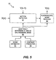
- Fig. 5 is a block diagram functionally illustrating the components of the FNR algorithm of the present invention in accordance with the preferred embodiment.
- Fig. 6 is a graphic representation of matching of system responses for a temporal sampling rates of 30 frames per second (fps) and 15 fps.
- Fig. 7 is a graphic representation of matching of system responses for a temporal sampling rates of 30 frames per second (fps) and 7.5 fps.
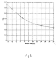
- Figure 8 is a graphic depiction of predicted weighting values for use in Fluoroscopic Noise Reduction correction system in accordance with this invention for a variety of sampling rates.
- Fig. 1 is a functional block diagram illustrating the x-ray fluoroscopy system 1 of the present invention that implements the adaptive FNR algorithm of the present invention.
- the x-ray fluoroscopy system 1 of the present invention comprises a fluoroscopic x-ray source 16, which projects x-rays onto a patient 18, and a fluoroscopic x-ray detector component 15, which detects x-rays impinging thereon and generates fluoroscopic image data.
- the system 1 also comprises a computer 10 that processes the fluoroscopic image data generated by the fluoroscopic x-ray detector component 15, a memory device 12 and a display monitor 13.
- the adaptive FNR algorithm 20 of the present invention is not limited with respect to the type of x-ray fluoroscopy system with which the adaptive FNR algorithm 20 is utilized, as will be understood by those skilled in the art. It will also be understood by those skilled in the art that the x-ray fluoroscopy system 1 is not limited to any particular components. For example, it is well known in the art of fluoroscopy that various types of fluoroscopic x-ray detector components can be utilized for capturing x-rays and for producing fluoroscopic x-ray image data. It is also well known that various types of fluoroscopic viewing systems are available that are suitable for use with x-ray fluoroscopy systems.
- the fluoroscopic x-ray detector component 15 comprises a digital flat-panel x-ray detector.
- Digital flat-panel x-ray detectors are known in the art.
- a detector of this type that is suitable for use with the present invention utilizes a cesium iodide scintillator that absorbs x-ray photons and converts them into light. The light is converted into electronic energy by an array of photodiodes comprised in the detector.
- the detector comprises read-out electronics that convert the electronic charge at each pixel into digital data that is suitable for image processing by the computer 10.
- an image intensifier (not shown) receives x-rays and converts the x-rays into light photons, which are then converted into electrical analog signals. These electrical analog signals may then be converted into digital signals that are suitable for processing by the computer 10.
- the computer 10 is connected to the fluoroscopic x-ray source 16 and to the fluoroscopic x-ray detector component 15.
- the computer 10 controls the data acquisition process performed by the fluoroscopic x-ray source 16 in cooperation with the fluoroscopic x-ray detector component 15.
- the computer 10 may be connected to a memory device 12, which may be used for storing programs and data.
- the computer 10 preferably is also connected to a display monitor 13 to enable the x-ray image data that is processed in accordance with the adaptive FNR algorithm 20 to be displayed on the display monitor 13.
- the adaptive FNR algorithm 20 is implemented in software, which is executed by the computer 10.
- the adaptive FNR algorithm 20 may be implemented solely in hardware or in a combination of hardware and software.
- the computer 10 is not limited to any particular type of computer.
- the term "computer”, as that term is used herein, is intended to denote any machine capable of performing the calculations, or computations, necessary to perform the tasks of the present invention. In essence, this includes any machine that is capable of accepting a structured input and of processing the input in accordance with prescribed rules to produce an output. Therefore, those skilled in the art will understand that the computer 10 is not limited to any particular physical, structural, or electrical configuration.
- Fig. 2 is a flow chart illustrating the functions of the adaptive FNR algorithm 20 of the present invention.
- the adaptive FNR algorithm 20 of the present invention estimates noise statistics and predicts the contrast of an object of interest.
- the FNR algorithm 20 preferably adapts the noise estimation and contrast prediction on a regional, or pixel-by-pixel, basis.
- the adapted noise statistics and contrast are then utilized by the FNR algorithm 20 to adaptively define the motion detection window of the FNR algorithm 20 and to adaptively define the extent of temporal filtering to be performed on the image data.
- "adaptively define” and the like refer to changing parameters that control the discrimination of the object to be imaged from the background and changing parameters with respect to the extent of temporal filtering, as described further herein.
- the FNR algorithm 20 will perform adequately without adapting the estimation of noise statistics and the prediction of object contrast on a regional basis. However, the FNR algorithm 20 will perform more robustly (e.g., provide improved object discrimination and noise reduction) if its parameters are adapted using a noise statistics estimation and an object contrast prediction that have been adapted on a regional basis. Therefore, the present invention will be discussed in accordance with one embodiment wherein the noise statistics estimation and the object contrast prediction are adapted on a regional basis.
- the mean photon count is first determined, as indicated by block 21.
- Fluoroscopic x-ray detector components which are typically referred to as flat panels, have a finite gain, which is related to the conversion factor of the panel.
- the amount of noise is estimated from the number of electrons associated with the mean photon count, as indicated by block 23. The manner in which the noise statistics associated with the fluoroscopic x-ray detector component 15 are determined will be discussed in detail below with the respect to Fig. 3.
- the contrast of the object of interest is predicted, as indicated by block 25.
- objects such as stents or guidewires are manipulated in the patient's body in an area being imaged by the x-ray fluoroscopy system.
- the contrast of the object will depend on many factors, including the shape, size and composition of the object.
- the contrast of the object will also depend on other factors, including the size of the patient and the characteristics of the fluoroscopic x-ray detector component, imaging geometry and x-ray source.
- a model that predicts the contrast of the object in the patient's body for a given set of acquisition parameters can be generated.
- the model typically is based on physics and historical data. The manner in which such a model is generated will be understood by those skilled in the art. Therefore, a detailed discussion of the manner in which an object of interest, such as a stent, can be modeled will not be provided herein in the interest of brevity.
- the step of predicting the contrast of an object of interest commonly is implemented in the form of a look-up table (not shown). Models of various objects that are typically used in x-ray fluoroscopy are generated and the predictions regarding the contrast of the objects and these predictions are stored in a look-up table.
- the person performing the procedure Prior to performing an x-ray fluoroscopy procedure on a patient, the person performing the procedure inputs data into the x-ray fluoroscopy system 1 relating to the object and the size and weight of the patient.
- the look-up table which may be contained in the memory device 12, for example, outputs a minimal contrast prediction associated with the information input by the person performing the procedure and the system acquisition parameters.
- the contrast prediction and the noise statistics estimation are then utilized to adapt, if necessary, the FNR parameters, as indicated by block 27.
- the FNR algorithm 20 then performs fluoroscopic noise reduction using the adapted FNR parameters to adapt the motion detection window and the extent of temporal filtering performed, as indicated by block 29.
- the absolute contrast, also referred to herein as the gray level difference, associated with the object and the noise statistics estimation typically are adapted, or updated, in real time on a regional basis to thereby enable the parameters of the FNR algorithm to be adapted on a regional basis.
- the manner in which the gray level difference associated with the object and the noise statistics estimation are adapted on a regional basis will be discussed below with reference to FIGS. 3 and 4.
- EM exposure management
- the x-ray fluoroscopic detector component 15 has a detector dose associated with it, the characteristics of which are determined by the x-ray spectrum (i . e ., the distribution of x-ray photons as a function of energy), the spectral filters, the attenuation path, the current used to drive the x-ray source 16, and the imaging geometry.
- the spectral filters typically are comprised of copper, which is capable of filtering x-rays.
- the spectral filters (not shown) are typically located adjacent the x-ray source 16 in the path of the x-ray beam.
- each frame is acquired by pulsing the x-ray tube (not shown) of the x-ray source 16 for a finite duration, which is commonly referred to as the pulse width of the x-ray source 16.
- the pulse width is typically between 1 and 20 milliseconds.
- the source-to-image distance (SID) and the source-to-object (SOD) determine the object magnification.
- the exposure management (EM) parameters include all of these acquisition parameters, i . e ., the pulse width, the frame rate, the peak voltage of the tube (KVp), the current being used to drive the x-ray source 16, the spectral filters and the detector dose.
- a grid (not shown) is often disposed adjacent the x-ray fluoroscopic detector component 15 in the path of the x-ray beam. This grid lessens the contrast reduction resulting from scattered photons, but also further attenuates the x-ray beam. Finite focal spot size reduces contrast, especially for small objects, and the reduction is magnification dependent. These factors are also exposure management factors that should be taken into account in determining the object contrast. Contrast is also highly dependent on the material comprising the object. Generally, materials comprised of elements which have high atomic numbers absorb x-ray photons more effectively and hence produce more contrast when compared to the background.
- Fig. 3 is a flow chart functionally illustrating the steps performed in order to estimate the noise statistics.
- the flow chart of Fig. 3 corresponds to the step represented by block 23 in Fig. 2.
- the x-ray spectrum corresponds to the distribution of the photons as a function of the energy associated with the photons, which is determined by the peak voltage (KVp), by the target material and by the target angle of the x-ray beam.
- the x-ray spectrum associated with the fluoroscopic x-ray detector component 15 is calculated prior to performance of the FNR algorithm 20 and is stored in a file in memory, such as in memory device 12. For each peak voltage target angle and target material, an x-ray spectrum is stored in the file.
- the x-ray spectrums stored in the file preferably correspond to an x-ray source drive current of 1 milliamp (mA).
- the FNR algorithm 20 obtains the appropriate spectral file for a given peak voltage, target angle and target material from the file stored in memory.
- the flux is then modified to take into account any spectral filters being used as well as the filtering characteristics associated with the patient's body, as indicated by block 33.
- a size predictor which is normally implemented in typical x-ray fluoroscopy systems, is utilized to predict the acrylic equivalent attenuation (that is, using acrylic material to simulate tissue) through the patient.
- the flux associated with the spectral file is scaled for tube efficiency and for the actual current value to be utilized.
- the flux of the spectral file is then further modified in accordance with the inherent filtration characteristics of the tube, spectral filters and acrylic equivalent patient thickness, and the absorption of the x-ray spectrum on the detector is modeled, as indicated by block 35.
- the noise statistics are estimated for an average background taking into account properties of the detector component 15 and electronic noise contribution associated with the x-ray dose being used, as indicated by block 37.
- the number of photons per pixel corresponding to the modified x-ray spectrum is computed by pooling both scatter and primary components together.
- a "Swank Factor" for the resulting modified x-ray spectrum is then computed.
- the term "Swank Factor” is well known in the literature and results from the non-mono-energetic nature of an x-ray beam which undergoes a conversion process in a scintillator.
- the energy deposited on the detector component 15 for the generated background is computed using the model of the absorption of the modified x-ray spectrum generated in step 35, by determining the number of photons that are associated with the absorption model and by predicting conversion of the photons into electrons.
- the noise statistics associated with the electrons are estimated after taking into account any reduction in noise due to scintillator smoothing.
- the noise statistics are scaled using a regional mean that is calculated using an image frame that has been noise reduced in accordance with the FNR algorithm 20 of the present invention, as indicated by block 39.
- the regional mean can be obtained by simply averaging a group of pixels neighboring the pixel of interest in the most recent noise-reduced image frame.
- the noise statistics estimation is adapted on a regional basis by scaling it using this regional mean.
- Fig. 4 is a flow chart illustrating the steps performed by the adaptive FNR algorithm 20 of the present invention in predicting the contrast of the object of interest.
- the flow chart of Fig. 4 corresponds to the step represented by block 25 in Fig. 2.
- the process of predicting the contrast of the object of interest is performed prior to the performance of a fluoroscopic x-ray procedure on a patient.
- the contrast for various objects of interest preferably is pre-computed and stored in memory (e.g., in a look-up table), which may be memory device 12.
- a real-time scatter estimate is obtained during the procedure and is used to update the pre-computed object contrast.
- the term "contrast” is used herein to denote a difference between the gray-level intensity of the object of interest and the intensity of the background, and by dividing the difference by the intensity of the background.
- the contrast is defined as (A-B)/A.
- the contrast, or intensity difference is predicted, or pre-computed, and then the predicted intensity difference is updated on a regional basis, i.e., on a pixel-by-pixel basis, by estimating the regional mean.
- the look-up table When a specific protocol is selected, i . e ., when the x-ray parameters and the object of interest have been selected, the look-up table outputs the contrast prediction associated with the selected object.
- the contrast prediction is then used by the adaptive FNR algorithm 20 of the present invention during the x-ray procedure being performed on the patient.
- the acquisition parameters preferably are utilized to obtain the addresses in the look-up table. The manner in which the contrast prediction is used by the adaptive FNR algorithm 20 will be discussed below in detail with reference to Fig. 5.
- the first step in the process of predicting the contrast of an object of interest is to generate the x-ray spectrum, as indicated by block 41.
- This step is essentially identical to the step represented by block 31 in Fig. 3.
- the image background on the detector will be generated, as indicated by block 43.
- the adaptive FNR algorithm 20 uses the patient size predictor discussed above to predict the acrylic equivalent attenuation through the patient.
- the energy deposited on the detector component 15 for the background is then computed on a sub-pixel basis by modeling the absorption of the modified x-ray spectrum in accordance with the scintillator material of the detector component 15 and the production of light photons, and by predicting the conversion of light photons into electrons. Factors such as the scatter and primary contributions associated with the imaging geometry, the patient thickness and the grid behavior are then taken into account to obtain the final image background.
- the object profile is generated, as indicated by block 45.
- the shape of the object of interest and the composition of the object of interest are known.
- the clinical protocol to be utilized in a given procedure is also known.
- the object to be optimized typically is a guidewire having a diameter of 0.014 inches.
- the object to be optimized is a guide catheter.
- Another example of a type of clinical protocol is a contrast injection procedure. In this type of procedure, the object of interest is the artery of a predetermined diameter, which is filled with contrast material.
- the attenuation path that will be encountered by the x-ray beam can be generated.
- Those skilled in the art will understand the manner in which such an attenuation path can be generated given that the shape and characteristics of the object of interest are known and the clinical protocol to be utilized and the acquisition parameters associated therewith are known. Therefore, a detailed discussion of the manner in which such an attenuation path is generated for a particular object of interest will not be provided herein in the interest of brevity.
- the ratio of the source-to-image distance (SID) to the source-to-object distance (SOD) is then utilized to obtain an appropriate geometric magnification.
- the projection image on the object of interest is generated using the obtained geometric magnification. This is the final step in generating the object profile. Once the object profile has been generated, the object projection on the detector component 15 is generated, as indicated by block 47.
- the patient size predictor discussed above is utilized to predict the acrylic equivalent attenuation through the patient.
- the x-ray flux associated with the modified x-ray spectrum is then modified in accordance with the patient equivalent acrylic thickness. This modified x-ray flux is then utilized to generate a projection of the magnified object.
- the energy deposited on the detector component 15 for the object of interest is then computed on a sub-pixel basis by modeling the absorption of the modified x-ray spectrum in correspondence with the scintillator material of the detector component 15, the number of light photons produced, and the conversion of the light photons into electrons. All of the points in the synthetic image are then replaced by the background obtained in the step represented by block 43 wherever the object of interest does not exist.
- the projection is then modified in accordance with the modulation transfer function (MTF) of the detector component 15, which typically is known for a given fluoroscopic detector component.
- MTF modulation transfer function
- the projection is further modified by taking into account the finite focal spot blurring.
- the projection is then modified in accordance with the scatter and primary components resulting from modeling the imaging geometry, air gap, field of view, the patient thickness and the grid behavior.
- the inherent temporal lag of the fluoroscopic system 1 is then taken into account to obtain the final object projection on the detector component 15.
- Blocks 49 and 51 in FIG. 4 represent the calculation of the regional mean and the scaling of the object contrast based on the regional mean, respectively.
- the estimated noise statistics and the predicted contrast are adapted on a regional basis to obtain regional estimated noise statistics and a regional absolute contrast associated with the object.
- the adapted noise statistics and contrast are utilized to adaptively alter the parameters of the FNR algorithm 20. Fluoroscopic noise reduction is then performed by utilizing the adapted parameters to alter, if necessary, the motion detection window and the extent of temporal filtering performed on the image. The manner in which these functions are performed will now be described with reference to Fig. 5.
- Fig. 5 is a block diagram illustrating the functional components of the adaptive FNR algorithm 20 of the present invention in accordance with the preferred embodiment.
- Block 47 represents the motion discrimination process and block 53 represents the noise reduction process.
- Block 43, 45 and 51 will be discussed below in detail. However, prior to discussing all of these blocks in detail, a discussion will be provided of the manner in which the variables A1 and A2 shown in block 51 are obtained.
- variable ⁇ represents the difference between the input value of pixel i in a low pass filtered frame n and the same pixel output value in a low pass filtered output frame n-1, which corresponds to the previous frame. Therefore, the variable ⁇ can be expressed as X_bar i(n) - Y_bar i(n-1).
- the variable EM represents the exposure management trajectory parameters and the variable STRENGTH represents the baseline strength of the filter, which preferably is selected by the user.
- the NOISE and CONTRAST parameters represent the adapted noise statistics estimation and the adapted object absolute contrast, respectively, obtained in the manner discussed above with reference to Figs. 1-4.
- the function f1 is multiplied by Xi(n), which corresponds to the value of the input pixel i in frame n. This function determines the percentage of the value of the input pixel i in frame n that will be contained in the output value for the pixel i in frame n, which is represented by Yi(n).
- the regional noise statistics estimation and the regional contrast prediction are taken into account in determining the amount of the value of the input pixel i that will be contained in the output value of the pixel i.
- the regional noise estimation and the regional contrast prediction are taken into account in determining the extent of temporal filtering that will be performed on the input pixel.
- the exposure management (EM) parameters are also taken into account in determining the extent of temporal filtering that will be performed on the input pixel.
- the function f2 generally represents some combination of past input images and past output images that have been temporally filtered, i . e ., noise reduced. Therefore, the output value of pixel i for frame n retains a percentage of these past filtered values in the output value of pixel i, Yi(n).
- functions f1 and f2 operate in a manner analogous to a sliding scale such that more or all of the input value of pixel i and less or none of the temporally filtered image are contained in the output value of pixel i when motion exists. Conversely, less of the input value of pixel i and more of the temporally filtered image are contained in the output value of pixel i when no motion exists.
- the variable A2 is obtained from the regionally-adapted noise statistics estimation and absolute contrast prediction. Therefore, the NOISE and CONTRAST prediction variables shown in Equation 1 have been replaced with the variable A2 in Equation 2. Although the variable A2 takes the EM parameters into account by virtue of the fact that A2 is dependent on the noise statistics estimation and on the object contrast prediction, EM is shown as a separate variable in Equation 2. This provides flexibility in the manner in which f1 is implemented by allowing changes in EM parameters to be factored into Equation 2 without requiring a change in the value of A2.
- the variable A2 functions as a threshold value that is used to detect motion in the input image frame.
- the value of the variable A2 is adapted in accordance with the regionally-adapted noise statistics estimation and object absolute contrast prediction. Therefore, the value of the variable A2 is adapted on a regional basis.
- the motion discrimination window of the FNR algorithm 20 is also adapted on a regional basis.
- the value of the variable A2 is compared with the value of ⁇ to determine the value of the function f1. Specifically, when ⁇ is less than the value of A2, a determination is made by the FNR algorithm 20 that no motion exists and Equation 2 may be altered such that the function f1 is simply set equal to the value of the variable A1.
- the function f2 is set equal to Yi(n-1), which is the output value of pixel i in the previous frame.
- the function f1 When ⁇ is greater than the value of A2, the function f1 is set equal to 1 and the value of the output pixel is simply assigned the value of the input pixel and no temporal filtering is performed. It will be noted that the function f2 as stated in Equations 1 and 2 is a much more generalized expression of this function than the expression given for this function in Equation 4. The function f2 as stated in Equations 1 and 2 allows the type of past image data retained in the output of the FNR process to be greatly varied, which enhances the ability to optimize the FNR process.
- the value of the variable A1 preferably is varied in accordance with the difference between ⁇ and the value of the variable A2.
- ⁇ is much less than the value of the variable A2
- the input pixel is clearly outside of the motion discrimination window. Therefore, in this case, the extent of temporal filtering performed on the input pixel will be relatively large.
- ⁇ is only slightly less than the value of the variable A2
- this difference indicates a boundary in the image between a region of motion and a region of non-motion. In this region, the extent of temporal filtering performed on the input pixel will be relatively small.
- the thresholding mechanism utilized by the FNR algorithm 20 to perform motion discrimination is non-linear in that the magnitude of the difference between ⁇ and the value of the variable A2 determines the extent of temporal filtering to be performed when ⁇ is less than the value of the variable A2.
- the thresholding mechanism is adaptable on a regional basis, which results in the motion discrimination window and the extent of temporal filtering performed also being adaptable on a regional basis.
- This overall adaptability of the FNR algorithm 20 allows fluoroscopic noise reduction to be optimized and to be dynamically adapted on a pixel-by-pixel and frame-to-frame basis.
- Fig. 5 is a block diagram illustrating the functional components of the adaptive FNR algorithm 20 of the present invention.
- Block 47 represents the motion detection process during which the FNR algorithm 20 determines whether or not the input pixel corresponds to motion in the image frame.
- Block 53 represents the noise reduction process performed when a determination is made that the input pixel corresponds to no motion.
- Blocks 43 and 45 represent, respectively, the processes of estimating the noise statistics on a regional basis and of predicting the absolute contrast for the object of interest on a regional basis.
- Block 51 represents the utilization of the adapted estimation of noise statistics and the adapted absolute contrast to adapt the parameters A1 and A2 accordingly.
- the arrows directed from block 51 to blocks 47 and 53 indicate that parameter A1 is used during the noise reduction process and that the parameter A2 is used during the motion discrimination process, as described above with reference to the equations.
- the parameter A2 is used to adapt the parameter A1, which is then utilized to perform noise reduction in the manner described above with reference to Equation 5.
- Mathematical modeling of the system may be applied as a means to prescribe settings for the adapted parameters. As EM parameters or patient characteristics vary, other system variables are modified from their normal operating values via consideration of a system model in order to maintain similar quality in the x-ray imaging process.
- the FNR algorithm of the present invention can be adapted to include a temporal adaptive feature to account for changing temporal characteristics of the process (as used herein, "adapted to” and the like refer to programming or embedding an algorithm in a computer or chip to process data in accordance with a desired use of the algorithm).
- a means of modifying the FNR parameters can be derived in order to provide the same imaging performance within the "system.”
- the "system” is said to consist of the x-ray source, object/background, x-ray detector, processing, monitor, and the human observer.
- H eye ( f ) sin( ⁇ fT int )/( ⁇ fT int ).
- H system ( f ) H fps ( f ) H FNR ( f ) H eye ( f ).
- a 1 is accomplished by matching (e.g., in least squares sense, visual, etc.) the spectrum to that of the reference case.
- FNR value A 1 0.24.
- Two examples of A 1 -synthesis (visual matching) are presented in Figures 6 and 7.
- Figure 6 presents response data (dB) from the model for a 30 fps sampling rate in curve 610; corresponding model data for 15 fps sampling rate is shown curve 620 for the respective values of f1.
- the curve shown in Figure 8 was generated.
- the function f2 has been illustrated as being dependent upon various present and past filtered image frames, this is intended to demonstrate the preferred dependencies of f2 and not to demonstrate the only possible dependencies for the function f2.
- the past and present filtered image data preferably are used to generate f2 because these image frames have already been noise reduced.
- the function f2 could simply be based on the filtered output pixel, Yi(n-1), for the previous frame.
- the functions f1 and f2, and the variable A2 are not limited to any particular functions but generally will be defined by various general rules that optimize the FNR process. For example, the following rules will apply to the behavior of the function f1. As the gray-level intensity of a region decreases, the function f1 decreases from the baseline value, which is a function of regional statistics. As strength increases, the function f1 decreases. As the power of the x-ray tube approaches its limit, f1 decreases from the baseline value. As ⁇ increases, f1 increases and approaches 1 for values that are greater than or equal to A2. As pulse width increases, f1 increases.. As noise increases, f1 decreases. As the regulatory limit on patient dose is approached, f1 decreases.
- this function preferably is defined as a linear combination of its variables, although this does not have to be the case.
- the strength of the spatial and temporal filters utilized by the FNR algorithm 20 to perform low pass filtering increases.
- A2 increases as intensity decreases.
- A2 increases as the power of the x-ray tube increases.
- A2 increases from the baseline value.
- pulse width increases, A2 remains the same or decreases.
- contrast decreases, A2 decreases.
- A2 increases.
Landscapes
- Engineering & Computer Science (AREA)
- Physics & Mathematics (AREA)
- Theoretical Computer Science (AREA)
- General Physics & Mathematics (AREA)
- Health & Medical Sciences (AREA)
- Life Sciences & Earth Sciences (AREA)
- Multimedia (AREA)
- Signal Processing (AREA)
- Medical Informatics (AREA)
- Radiology & Medical Imaging (AREA)
- General Health & Medical Sciences (AREA)
- Pathology (AREA)
- Nuclear Medicine, Radiotherapy & Molecular Imaging (AREA)
- Biomedical Technology (AREA)
- Heart & Thoracic Surgery (AREA)
- Molecular Biology (AREA)
- Surgery (AREA)
- Animal Behavior & Ethology (AREA)
- Optics & Photonics (AREA)
- Public Health (AREA)
- Veterinary Medicine (AREA)
- High Energy & Nuclear Physics (AREA)
- Biophysics (AREA)
- Apparatus For Radiation Diagnosis (AREA)
- Image Processing (AREA)
- Image Analysis (AREA)
Applications Claiming Priority (2)
| Application Number | Priority Date | Filing Date | Title |
|---|---|---|---|
| US09/465,313 US6314160B1 (en) | 1999-12-17 | 1999-12-17 | Method and apparatus for performing fluoroscopic noise reduction |
| US465313 | 1999-12-17 |
Publications (2)
| Publication Number | Publication Date |
|---|---|
| EP1109401A2 true EP1109401A2 (de) | 2001-06-20 |
| EP1109401A3 EP1109401A3 (de) | 2005-05-04 |
Family
ID=23847291
Family Applications (1)
| Application Number | Title | Priority Date | Filing Date |
|---|---|---|---|
| EP00311256A Withdrawn EP1109401A3 (de) | 1999-12-17 | 2000-12-15 | Verfahren und Gerät zur Verringerung von fluoroskopischen Geraüsch |
Country Status (4)
| Country | Link |
|---|---|
| US (1) | US6314160B1 (de) |
| EP (1) | EP1109401A3 (de) |
| JP (1) | JP2001238869A (de) |
| CN (1) | CN1151663C (de) |
Cited By (3)
| Publication number | Priority date | Publication date | Assignee | Title |
|---|---|---|---|---|
| EP1643757A1 (de) * | 2004-09-30 | 2006-04-05 | General Electric Company | Systeme und Verfahren zur dynamischen Bildoptimierung |
| WO2008119480A3 (en) * | 2007-03-31 | 2008-12-11 | Sony Deutschland Gmbh | Noise reduction method and unit for an image frame |
| EP3420905A1 (de) * | 2017-06-29 | 2019-01-02 | Koninklijke Philips N.V. | Bildkontrastverbesserung eines röntgenbildes |
Families Citing this family (27)
| Publication number | Priority date | Publication date | Assignee | Title |
|---|---|---|---|---|
| US6583420B1 (en) * | 2000-06-07 | 2003-06-24 | Robert S. Nelson | Device and system for improved imaging in nuclear medicine and mammography |
| US7054500B1 (en) * | 2000-12-06 | 2006-05-30 | Realnetworks, Inc. | Video compression and decompression system with postfilter to filter coding artifacts |
| FI113897B (fi) * | 2001-11-23 | 2004-06-30 | Planmed Oy | Automaattivalotusmenetelmä ja automaattivalotusjärjestelmä |
| FR2846504B1 (fr) * | 2002-10-29 | 2005-04-08 | Ge Med Sys Global Tech Co Llc | Procede de determination d'un bruit fluoroscopique |
| US7135686B1 (en) | 2002-11-19 | 2006-11-14 | Grady John K | Low noise x-ray detector for fluoroscopy |
| US6879660B2 (en) * | 2002-12-18 | 2005-04-12 | General Electric Company | Method and apparatus for reducing spectrally-sensitive artifacts |
| JP3992651B2 (ja) * | 2003-06-19 | 2007-10-17 | ジーイー・メディカル・システムズ・グローバル・テクノロジー・カンパニー・エルエルシー | 操作コンソール、x線透視撮影装置、及びその制御方法、システム |
| US7590306B2 (en) * | 2003-11-26 | 2009-09-15 | Ge Medical Systems Global Technology Company, Llc | Resolution adaptive image filtering system and method |
| FR2884948B1 (fr) * | 2005-04-26 | 2009-01-23 | Gen Electric | Procede et dispositif de reduction du bruit dans une sequence d'images fluoroscopiques |
| US8825138B2 (en) * | 2007-09-17 | 2014-09-02 | Wisconsin Alumni Research Foundation | Method for reducing motion artifacts in highly constrained medical images |
| US20090086911A1 (en) * | 2007-09-27 | 2009-04-02 | General Electric Company | Inspection tool for radiographic systems |
| US8908100B2 (en) * | 2007-12-28 | 2014-12-09 | Entropic Communications, Inc. | Arrangement and approach for motion-based image data processing |
| US8526700B2 (en) | 2010-10-06 | 2013-09-03 | Robert E. Isaacs | Imaging system and method for surgical and interventional medical procedures |
| US11231787B2 (en) | 2010-10-06 | 2022-01-25 | Nuvasive, Inc. | Imaging system and method for use in surgical and interventional medical procedures |
| US9785246B2 (en) | 2010-10-06 | 2017-10-10 | Nuvasive, Inc. | Imaging system and method for use in surgical and interventional medical procedures |
| FR2978273B1 (fr) * | 2011-07-22 | 2013-08-09 | Thales Sa | Procede de reduction du bruit dans une sequence d'images fluoroscopiques par filtrage temporel et spatial |
| DE102011054056A1 (de) | 2011-09-29 | 2013-04-04 | Jenoptik Optical Systems Gmbh | Verfahren zur Rauschunterdrückung in Bildern einer Bildsequenz |
| US9269128B2 (en) | 2012-05-23 | 2016-02-23 | Snu R&Db Foundation | Method for reducing noise in medical image |
| US9076237B2 (en) * | 2013-03-12 | 2015-07-07 | Wisconsin Alumni Research Foundation | System and method for estimating a statistical noise map in x-ray imaging applications |
| KR102060659B1 (ko) | 2013-03-20 | 2019-12-30 | 삼성전자주식회사 | 영상 처리를 위한 투사 및 역투사 방법 및 그 영상 처리 장치 |
| JP6188488B2 (ja) * | 2013-08-27 | 2017-08-30 | キヤノン株式会社 | 画像処理装置、画像処理方法及びプログラム |
| US10275971B2 (en) * | 2016-04-22 | 2019-04-30 | Ncr Corporation | Image correction |
| CN105943067B (zh) * | 2016-06-06 | 2018-11-20 | 辽宁开普医疗系统有限公司 | 一种x射线质量对比评估装置及方法 |
| EP3578102B1 (de) * | 2018-06-07 | 2021-05-19 | Siemens Healthcare GmbH | Verfahren zum betreiben eines medizinischen röntgengerätes; sowie röntgengerät |
| CN111096761B (zh) * | 2018-10-29 | 2024-03-08 | 上海西门子医疗器械有限公司 | 修正楔形滤波器散射的方法、装置和相关设备 |
| WO2021163022A1 (en) | 2020-02-11 | 2021-08-19 | Subtle Medical, Inc. | Systems and methods for real-time video enhancement |
| WO2021246998A1 (en) * | 2020-06-01 | 2021-12-09 | American Science And Engineering, Inc. | Systems and methods for controlling image contrast in an x-ray system |
Family Cites Families (5)
| Publication number | Priority date | Publication date | Assignee | Title |
|---|---|---|---|---|
| US4367490A (en) | 1981-04-24 | 1983-01-04 | General Electric Company | Noise reduction in digital fluoroscopy systems |
| US5091925A (en) * | 1990-01-18 | 1992-02-25 | Siemens Aktiengesellschaft | X-ray diagnostics installation with spatial frequency filtering |
| DE69322444T2 (de) * | 1992-07-10 | 1999-06-24 | Koninklijke Philips Electronics N.V., Eindhoven | Röntgendurchleuchtungsgerät mit Mitteln zur Rauschreduktion |
| DE4342476C2 (de) * | 1993-12-13 | 1995-12-14 | Siemens Ag | Röntgendiagnostikeinrichtung |
| FR2736182A1 (fr) * | 1995-06-30 | 1997-01-03 | Philips Electronique Lab | Procede de traitement d'images pour la reduction du bruit dans une image d'une sequence d'images numeriques et dispositif mettant en oeuvre ce procede |
-
1999
- 1999-12-17 US US09/465,313 patent/US6314160B1/en not_active Expired - Fee Related
-
2000
- 2000-12-15 JP JP2000381167A patent/JP2001238869A/ja not_active Withdrawn
- 2000-12-15 EP EP00311256A patent/EP1109401A3/de not_active Withdrawn
- 2000-12-18 CN CNB001356720A patent/CN1151663C/zh not_active Expired - Fee Related
Cited By (5)
| Publication number | Priority date | Publication date | Assignee | Title |
|---|---|---|---|---|
| EP1643757A1 (de) * | 2004-09-30 | 2006-04-05 | General Electric Company | Systeme und Verfahren zur dynamischen Bildoptimierung |
| WO2008119480A3 (en) * | 2007-03-31 | 2008-12-11 | Sony Deutschland Gmbh | Noise reduction method and unit for an image frame |
| US8339516B2 (en) | 2007-03-31 | 2012-12-25 | Sony Deutschland Gmbh | Noise reduction method and unit for an image frame |
| EP3420905A1 (de) * | 2017-06-29 | 2019-01-02 | Koninklijke Philips N.V. | Bildkontrastverbesserung eines röntgenbildes |
| WO2019002560A1 (en) * | 2017-06-29 | 2019-01-03 | Koninklijke Philips N.V. | ENHANCEMENT OF IMAGE CONTRAST OF A RADIOGRAPHIC IMAGE |
Also Published As
| Publication number | Publication date |
|---|---|
| CN1301025A (zh) | 2001-06-27 |
| EP1109401A3 (de) | 2005-05-04 |
| CN1151663C (zh) | 2004-05-26 |
| US6314160B1 (en) | 2001-11-06 |
| JP2001238869A (ja) | 2001-09-04 |
Similar Documents
| Publication | Publication Date | Title |
|---|---|---|
| US6314160B1 (en) | Method and apparatus for performing fluoroscopic noise reduction | |
| DE69322444T2 (de) | Röntgendurchleuchtungsgerät mit Mitteln zur Rauschreduktion | |
| US5960058A (en) | Method for generating X-ray image and apparatus therefor | |
| CN107533755B (zh) | 用于改进医学图像质量的设备和方法 | |
| US7233689B2 (en) | Method of processing images for digital subtraction angiography | |
| KR102201407B1 (ko) | 엑스선 영상장치 및 그 제어방법 | |
| US6621887B2 (en) | Method and apparatus for processing a fluoroscopic image | |
| US6760401B2 (en) | Apparatus and method for processing of digital images | |
| US5293415A (en) | X-ray fluoroscopy system for reducing dosage employing iterative power ratio estimation | |
| JP4020966B2 (ja) | 画像内のノイズ減少方法 | |
| KR102448069B1 (ko) | 방사선 촬영에 의해 획득된 영상에 포함된 노이즈를 저감하기 위한 영상 처리 방법 및 장치 | |
| Aufrichtig et al. | X-ray fluoroscopy spatio-temporal filtering with object detection | |
| US12254973B2 (en) | Computer-implemented method for providing an output data set | |
| Wilson et al. | Perception of temporally filtered X-ray fluoroscopy images | |
| JPH09128532A (ja) | ディジタル画像のシーケンスの画像内のノイズの時間的フィルタリングの方法及び装置 | |
| US20100104165A1 (en) | Radiation image processing apparatus, image processing method, x-ray radioscopy apparatus and control method thereof | |
| US10736591B2 (en) | Control device, control method, and program | |
| FR2736181A1 (fr) | Procede de traitement d'images pour la reduction du bruit dans une image d'une sequence d'images numeriques et dispositif mettant en oeuvre ce procede | |
| EP0578311B1 (de) | Röntgendurchleuchtungsgerät mit Mitteln zur Rauschreduktion | |
| Labbe et al. | The x‐ray fovea, a device for reducing x‐ray dose in fluoroscopy | |
| JP3410778B2 (ja) | リカーシブフィルタ、x線診断装置 | |
| JP6776171B2 (ja) | 放射線撮像装置、画像処理装置および画像処理用プログラム | |
| JP2002330341A (ja) | 放射線画像処理装置、画像処理システム、放射線画像処理方法、記録媒体、及びプログラム | |
| JP6795099B2 (ja) | 画像処理装置 | |
| Manjeshwar et al. | Quantitative fluoroscopic dose saving in cardiovascular imaging with a novel motion discriminating temporal filter |
Legal Events
| Date | Code | Title | Description |
|---|---|---|---|
| PUAI | Public reference made under article 153(3) epc to a published international application that has entered the european phase |
Free format text: ORIGINAL CODE: 0009012 |
|
| AK | Designated contracting states |
Kind code of ref document: A2 Designated state(s): AT BE CH CY DE DK ES FI FR GB GR IE IT LI LU MC NL PT SE TR |
|
| AX | Request for extension of the european patent |
Free format text: AL;LT;LV;MK;RO;SI |
|
| RIN1 | Information on inventor provided before grant (corrected) |
Inventor name: KAUTZ, GREGORY MICHAEL Inventor name: LEBIHEN, THIERRY Inventor name: DHAWALE, PARITOSH JAYANT |
|
| PUAL | Search report despatched |
Free format text: ORIGINAL CODE: 0009013 |
|
| AK | Designated contracting states |
Kind code of ref document: A3 Designated state(s): AT BE CH CY DE DK ES FI FR GB GR IE IT LI LU MC NL PT SE TR |
|
| AX | Request for extension of the european patent |
Extension state: AL LT LV MK RO SI |
|
| RIC1 | Information provided on ipc code assigned before grant |
Ipc: 7H 04N 5/21 B Ipc: 7G 06T 5/00 A |
|
| STAA | Information on the status of an ep patent application or granted ep patent |
Free format text: STATUS: THE APPLICATION IS DEEMED TO BE WITHDRAWN |
|
| 18D | Application deemed to be withdrawn |
Effective date: 20050701 |