EP1109615B1 - Verfahren und einrichtung zur kontrolle von ammoniak-schlupf in der reduktion von schwefeldioxidemissionen - Google Patents
Verfahren und einrichtung zur kontrolle von ammoniak-schlupf in der reduktion von schwefeldioxidemissionen Download PDFInfo
- Publication number
- EP1109615B1 EP1109615B1 EP99968640A EP99968640A EP1109615B1 EP 1109615 B1 EP1109615 B1 EP 1109615B1 EP 99968640 A EP99968640 A EP 99968640A EP 99968640 A EP99968640 A EP 99968640A EP 1109615 B1 EP1109615 B1 EP 1109615B1
- Authority
- EP
- European Patent Office
- Prior art keywords
- vessel
- ammonia
- scrubbing solution
- sulfur dioxide
- solution
- Prior art date
- Legal status (The legal status is an assumption and is not a legal conclusion. Google has not performed a legal analysis and makes no representation as to the accuracy of the status listed.)
- Expired - Lifetime
Links
Images
Classifications
-
- B—PERFORMING OPERATIONS; TRANSPORTING
- B01—PHYSICAL OR CHEMICAL PROCESSES OR APPARATUS IN GENERAL
- B01D—SEPARATION
- B01D53/00—Separation of gases or vapours; Recovering vapours of volatile solvents from gases; Chemical or biological purification of waste gases, e.g. engine exhaust gases, smoke, fumes, flue gases, aerosols
- B01D53/34—Chemical or biological purification of waste gases
- B01D53/46—Removing components of defined structure
- B01D53/48—Sulfur compounds
- B01D53/50—Sulfur oxides
- B01D53/501—Sulfur oxides by treating the gases with a solution or a suspension of an alkali or earth-alkali or ammonium compound
- B01D53/504—Sulfur oxides by treating the gases with a solution or a suspension of an alkali or earth-alkali or ammonium compound characterised by a specific device
-
- B—PERFORMING OPERATIONS; TRANSPORTING
- B01—PHYSICAL OR CHEMICAL PROCESSES OR APPARATUS IN GENERAL
- B01D—SEPARATION
- B01D2251/00—Reactants
- B01D2251/20—Reductants
- B01D2251/206—Ammonium compounds
- B01D2251/2062—Ammonia
Definitions
- This invention generally relates to processes by which sulfur dioxide gas is removed from utility and industrial flue gases. More particularly, this invention is directed to a wet flue gas desulfurization process and apparatus in which ammonium sulfate is produced as a valuable byproduct from sulfur dioxide removed from flue gases using an ammonia-containing scrubbing solution, in which free ammonia and ammonium sulfate aerosol in the scrubbed flue gases is controlled.
- Gas-liquid contactors and absorbers are widely used to remove substances such as gases and particulate matter from combustion or flue gases produced by utility and industrial plants. Often of particular concern are sulfur dioxide (SO 2 ) and other acidic gases produced by the combustion of fossil fuels and various industrial operations. Such gases are known to be hazardous to the environment, and their emission into the atmosphere is closely regulated by clean air statutes. The method by which these gases are removed with a gas-liquid contactor or absorber is known as wet flue gas desulfurization.
- the cleansing action produced by gas-liquid contactors and absorbers is generally derived from the passage of gas through a tower cocurrently or countercurrently to a descending liquid that absorbs sulfur dioxide.
- Wet flue gas desulfurization processes have typically involved the use of an alkaline scrubbing liquid, such as a calcium-based slurry or a sodium-based or ammonia-based solution.
- a slurry is a mixture of solids and liquids in which the content of the solids can be any desired level, including the extreme condition in which the slurry is termed a moist solid.
- Examples of calcium-based slurries are limestone (calcium carbonate; CaCO 3 ) slurries and hydrated lime (calcium hydroxide; Ca(OH) 2 ) slurries formed by action of water on lime (calcium oxide; CaO). Such slurries react with the acidic gases to form precipitates that can be collected for disposal, recycling or sale.
- salts such as calcium sulfite (CaSO 3 •1 ⁇ 2H 2 O), gypsum (CaSO•2H 2 O), calcium chloride (CaCl 2 ) and calcium fluoride (CaF 2 ).
- ammonia In addition to being required to react with sulfur dioxide to produce ammonium sulfate, ammonia also serves to increase the efficiency of sulfur dioxide removal by reducing the acidity of the ammonium sulfate solution, which becomes more acidic with the absorption of sulfur dioxide.
- Controlling the amount of free ammonia in the desulfurization process is in part a function of the ammonia vapor pressure, which results from a combination of pH and levels of unoxidized ammonium sulfite produced by the reaction of sulfur dioxide and ammonia in the absence of sufficient oxygen. High pH values result in high ammonia vapor pressure, which promotes ammonia slip. High levels of unoxidized ammonium sulfite also promote ammonia slip.
- EP0212523 discloses a method for scrubbing sulfur dioxide gas out of a sulfur dioxide contaminated gas in which aqueous ammonia and air are simultaneously introduced into a sulfur dioxide loaded scrubbing solution. However, the aqueous ammonia and air are introduced separately into the scrubbing solution through respective injection means.
- the present invention provides a process for removing sulfur dioxide from flue gases, the method comprising the steps of: delivering flue gases containing sulfur dioxide to a contactor region of an absorber; introducing a scrubbing solution containing ammonium sulfate into the absorber, the scrubbing solution contacting the flue gases and absorbing sulfur dioxide from the flue gases; accumulating the scrubbing solution containing the sulfur dioxide in a vessel having a bottom wall and a side wall that defines a cross-section of the vessel; introducing a dilute ammonia-containing fluid comprising ammonia and an oxygen-containing gas into the scrubbing solution within the vessel to react with the sulfur dioxide to produce ammonium sulfate, the dilute ammonia-containing fluid being introduced into the vessel in a direction toward the bottom wall of the vessel and dispersed evenly across the cross-section of the vessel at the bottom wall of the vessel; and recirculating the scrubbing solution to the contactor region, wherein the dilute ammonia-containing fluid
- the present invention provides a wet flue gas desulfurization process for removing sulfur dioxide from flue gases produced by processing operations of the type carried out in utility and industrial plants.
- the process utilizes an ammonium sulfate solution into which is injected ammonia and oxygen, which react with sulfur dioxide absorbed in the solution to produce ammonium sulfate as a valuable byproduct.
- the process of this invention generally entails the steps of delivering flue gases containing sulfur dioxide to a contactor region of an absorber, into which a scrubbing solution containing ammonium sulfate is introduced to contact the flue gases and absorb sulfur dioxide.
- the scrubbing solution containing the sulfur dioxide is then accumulated in a vessel having a bottom wall and a side wall that defines a cross-section of the vessel.
- An oxygen-containing gas and an ammonia-containing fluid are introduced together into the vessel to react with the sulfur dioxide to produce ammonium sulfate.
- the scrubbing solution is continuously recycled from the vessel to the contactor region.
- high pH values and high levels of unoxidized ammonium sulfite can result in high ammonia vapor pressure which promotes ammonia slip.
- localized high pH and ammonium sulfite levels within the scrubbing solution are inhibited by introducing dilute ammonia at the bottom wall of the vessel so that the ammonia is uniformly dispersed across the cross-section of the vessel prior to becoming intermixed with the remainder of the scrubbing solution in the vessel and prior to the scrubbing solution being recirculated to the contactor region of the absorber.
- the invention has shown that uniform dispersion of dilute ammonia eliminates pockets of high pH and ammonium sulfite levels in the scrubbing solution, yielding a more uniform and desirable pH level and reduced ammonium sulfite levels, which promote absorption of ammonia and control ammonia slip in the absorber.
- aqueous ammonia is diluted with air, which also serves as the oxygen source for the reaction, and then dispersed near the bottom wall of the vessel through a plurality of conduits that extend across the cross-section of the vessel.
- the conduits are preferably located above the inlet through which the scrubbing solution is recycled to the absorber. Dilution of the ammonia with water and air and the particular configuration of the conduits used to inject the mixture are both deemed to be preferred features of the invention that achieve the objects of the invention.
- the flue gas desulfurization process of this invention has the advantage of generating ammonium sulfate while controlling ammonia slip and the resulting ammonium sulfate aerosol.
- This process also reduces localized flashing (rapid boiling of water) due to the reaction of ammonia and water in the scrubbing solution, and minimizes flashing of ammonia into the gas phase due to depressurization of ammonium sulfate solution rich in ammonia as the solution is depressurized (expanded) across a nozzle used to atomize the solution in the contactor region of the absorber.
- ammonia is diluted and then uniformly dispersed at the bottom of the vessel has been shown to promote a more rapid reaction with sulfur dioxide.
- an improved flue gas desulfurization process and apparatus whereby sulfur dioxide gas entrained in a flue gas is removed through the use of scrubbing liquid to generate ammonium sulfate as a useful and valuable byproduct. While the invention will be described in reference to a desulfurization system that utilizes an absorber, those skilled in the art will recognize that the teachings of this invention can be readily applied to various other desulfurization systems, including gas-liquid contactors, scrubbing structures and various other equipment capable of being used in the process described for this invention. Furthermore, the desulfurization process of this invention is compatible with various systems capable of removing other undesirable gases, mist, dust, fumes, smoke and/or particulate matter from a stream of gas.
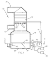
- FIG. 1 is a schematic view of a flue gas scrubbing apparatus 10 in accordance with this invention.
- the apparatus 10 includes an upright absorber 12 that is supplied with flue gases through an inlet duct 14.
- the apparatus 10 operates in a manner that causes absorption of sulfur dioxide from the flue gases using a scrubbing liquid.
- the scrubbed flue gases that leave the absorber 12 are delivered to a stack (not shown) or other suitable equipment through an outlet duct 20.
- the source of the flue gases may be any process involving the combustion of fossil fuels or various industrial operations by which undesirable gases or particulate matter are produced.
- the liquid is an ammonia-rich scrubbing solution 22, and more preferably an aqueous ammonium sulfate solution 22 containing free dissolved ammonia as the reagent for the desulfurization process.
- Figure 1 shows ammonia being delivered from a source 32 to a reaction vessel 18 via a pump 26, conduit 28 and injection system 30.
- the ammonia is preferably an aqueous solution of about 7:1 to 3:1 weight ratio of water to ammonia.
- Ammonia is a primary reactant when producing ammonium sulfate as a byproduct of the desulfurization process, and the ammonium sulfate solution 22 serves as the liquid vehicle for delivering the ammonia to the absorber 12.
- a recirculation pump 40 serves to recycle the ammonium sulfate solution 22 from the vessel 18 through a conduit 16 to a contactor region of the absorber 12, where the solution 22 is introduced through a number of nozzles 24 or other suitable devices.
- the scrubbing process involves spraying the ammonium sulfate solution 22 into the absorber 12 so as to provide intimate contact between the solution 22 and the flue gas.
- the solution 22 absorbs sulfur dioxide and other acid gases, such as hydrogen chloride (HCl) and hydrogen fluoride (HF), if they are present in the flue gases.
- the solution 22 then falls into the reaction vessel 18, where the absorbed sulfur dioxide reacts with the ammonia and is oxidized to form ammonium sulfate.
- ammonium sulfite (NH 4 ) 2 SO 3 •HOH) and ammonium bisulfite (NH 4 HSO 3 ), which are oxidized in the presence of sufficient oxygen to form ammonium sulfate and ammonium bisulfate (NH 4 HSO 4 ), the latter of which reacts with ammonia to form additional ammonium sulfate.
- ammonium sulfate solution 22 and/or ammonium sulfate crystals that form in the solution 22 can then be drawn off to yield the desired byproduct of this reaction.
- a sufficient amount of ammonium sulfate is preferably removed from the ammonium sulfate solution 22 prior to delivery to the absorber 12 in order to maintain ammonium sulfate at a desired concentration in the solution 22, which has typically been about 2% up to the saturation level of ammonium sulfate (46% total dissolved solids).
- a preferred solution has a dissolved concentration above 46% to about 48% total dissolved solids, so as to have suspended solids of ammonium sulfate precipitate in a range of preferably about 1% to 20% total suspended solids.
- sufficient ammonia is delivered to the vessel 18 to control the pH of the ammonium sulfate solution 22 within a typical range of about 4 to 6 pH range, such that the solution 22 is highly reactive for high efficient capture of sulfur oxide gases.
- a reaction occurs during the scrubbing operation between the injected ammonia and sulfur dioxide that, with forced oxidation, results in the production of additional ammonium sulfate.
- hydrogen chloride and/or hydrogen fluoride are present in the flue gas, as is the case with flue gas produced by the combustion of coal, these acidic gases are also captured to form ammonium chloride and ammonium fluoride.
- the present invention is based on the determination that the manner in which the prior art has injected ammonia promotes high levels of ammonia slip, meaning that free ammonia enters the absorber 12, some of which reacts with sulfur dioxide to form an ammonium sulfate aerosol, resulting in ammonia and ammonium sulfate aerosol escaping the absorber 12 and being discharged into the atmosphere.
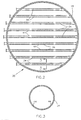
- the present invention entails injecting ammonia into the ammonium sulfate solution 22 in the reaction vessel 18 in a dilute form (with air and water) and through the injection system 30 shown in Figures 1 and 2, which in combination have been determined to reduce the likelihood of free ammonia escaping the absorber 12.
- ammonia slip occurs if ammonia is intentionally diluted with water and oxygen (e.g., air) prior to being injected evenly over the bottom cross-section of the vessel 18.
- oxygen e.g., air
- uniform dispersion of dilute ammonia has been shown to reduce the likelihood that pockets of high pH and high ammonium sulfite levels will be present in the solution 22, such that more uniform and desirable pH and ammonium sulfite levels are achieved that promote absorption of ammonia and control ammonia slip in the absorber 12.
- ammonia is diluted with oxygen from a suitable source 38, and the resulting mixture is then delivered through the conduit 28 to the vessel 18 via the injection system 30.
- Air is a suitable source for the oxygen, with a preferred ammonia:air weight ratio being about one to about five.
- the injection system 30 shown in Figures 1 and 2 includes a number of parallel conduits 34 that uniformly disperse the dilute ammonia near the bottom 36 of the reaction vessel 18, and preferably about ten feet (about three meters) from the bottom 36. To achieve the desired results, the conduits 34 are located above the inlet to the pump 40 and conduit 16. As shown in Figure 3, another feature of the injection system 30 is that the air/ammonia mixture is directed downward toward the bottom 36, and not horizontally or upward into the vessel 18. Injecting the mixture through apertures 44 having diameters of about three-eighths inch (about 9.5 millimeters) and at an angle of about 45 degrees to the bottom 36 has been shown to achieve the desired results.
- aqueous ammonia and oxygen introduced with the injection system 30 circulates through the reaction vessel 18 from the natural circulation established with the recirculation pump 40, the continuous injection of aqueous ammonia and air via the injection system 30, and any agitators present, such as the fan 42 shown in Figure 1.
- a significant advantage of the present invention is that, while prior art desulfurization processes that use ammonia-based scrubbing solutions have been prone to relative high levels of ammonia slip, the present invention controls ammonia slip by way of the manner in which ammonia is introduced into a flue gas desulfurization system to reduce the tendency for localized high pH and ammonium sulfite levels.
- Other advantages of this invention include minimized localized flashing due to reactions between ammonia and water in the solution 22, minimized flashing of ammonia into the gas phase when expanded through the nozzles 24, and a more rapid reaction of the solution 22 with sulfur dioxide.
Landscapes
- Engineering & Computer Science (AREA)
- Chemical & Material Sciences (AREA)
- Health & Medical Sciences (AREA)
- Biomedical Technology (AREA)
- Environmental & Geological Engineering (AREA)
- Analytical Chemistry (AREA)
- General Chemical & Material Sciences (AREA)
- Oil, Petroleum & Natural Gas (AREA)
- Chemical Kinetics & Catalysis (AREA)
- Treating Waste Gases (AREA)
Claims (21)
- Verfahren zum Entfernen von Schwefeldioxid aus Abgasen/Feuergasen, wobei das Verfahren folgende Schritte aufweist:Zuführen von schwefeldioxidhaltigen Abgasen an einen Kontaktierbereich eines Absorbers (12);Einbringen einer ammoniumsulfathaltigen Waschlösung (22) in den Absorber (12), wobei die Waschlösung (22) in Kontakt mit den Abgasen kommt und Schwefeldioxid aus den Abgasen absorbiert;Sammeln der schwefeldioxidhaltigen Waschlösung (22) in einem Behälter (18), der eine untere Wand (36) und eine einen Querschnitt des Behälters (18) begrenzende Seitenwand aufweist;Einbringen eines verdünntes Ammoniak enthaltenden Fluids, das Ammoniak und sauerstoffhaltiges Gas aufweist, in die Waschlösung (22) in dem Behälter (18) zum Reagieren mit dem Schwefeldioxid, um Ammoniumsulfat zu erzeugen, wobei das verdünntes Ammoniak enthaltende Fluid in den Behälter (18) in Richtung der unteren Wand (36) des Behälters (18) eingebracht wird und gleichmäßig quer durch den Querschnitt des Behälters (18) an der unteren Wand (36) des Behälters (18) verteilt wird; undZurückführen der Waschlösung (22) zu dem Kontaktierbereich, wobei das verdünntes Ammoniak enthaltende Fluid mit der Waschlösung (22) in dem Behälter (18) vermischt wird, bevor die Waschlösung (22) in dem Behälter (18) zu dem Kontaktierbereich zurückgeführt wird, um die Anteile der Waschlösung (22) in dem Behälter (18), die einen höheren pH-Wert und einen höheren Ammoniumsulfitpegel als der Rest der Waschlösung (22) in dem Behälter (18) haben, zu eliminieren.
- Verfahren nach Anspruch 1, wobei das sauerstoffhaltige Gas Luft ist.
- Verfahren nach Anspruch 1 oder 2, wobei die Waschlösung (22) gerührt wird, während sie in dem Behälter (18) ist.
- Verfahren nach einem der vorhergehenden Ansprüche, wobei die Waschlösung (22) in dem Behälter (18) bei einem pH-Wert von 4 bis 6 gehalten wird.
- Verfahren nach einem der vorhergehenden Ansprüche, wobei das verdünntes Ammoniak enthaltende Fluid das sauerstoffhaltige Gas und Ammoniak aufweist.
- Verfahren nach Anspruch 5, wobei das sauerstoffhaltige Gas Luft ist und das verdünntes Ammoniak enthaltende Fluid Ammoniak und Luft aufweist, die in einem Ammoniak/Luft-Gewichtsverhältnis von eins zu fünf gemischt sind.
- Verfahren nach einem der vorhergehenden Ansprüche, wobei der Schritt des Einbringens das Verteilen des verdünntes Ammoniak enthaltenden Fluids über eine Mehrzahl von parallelen Leitungen (34) quer durch den Querschnitt des Behälters (18) aufweist.
- Verfahren nach Anspruch 7, wobei die Leitungen (34) das verdünntes Ammoniak enthaltende Fluid in einem schrägen Winkel zur unteren Wand (36) des Behälters (18) einspritzen.
- Verfahren nach Anspruch 7 oder 8, wobei die Leitungen (34) das verdünntes Ammoniak enthaltende Fluid oberhalb eines Auslasses einspritzen, durch welchen die Waschlösung (22) zum Kontaktierbereich zurückgeführt wird.
- Verfahren nach Anspruch 1 oder 2, welches weiterhin aufweist: Zirkulieren der Waschlösung (22) von dem Behälter (18) zum Absorber (12), Rühren der Waschlösung (22) in dem Behälter (18) mit einer Rühreinrichtung (42), und Einbringen des verdünntes Ammoniak enthaltenden Fluids, das eine Mischung aus Luft und einer wässrigen Ammoniaklösung aufweist, in den Behälter (18) durch eine Einspritzeinrichtung, wobei die wässrige Ammoniaklösung ein Gewichtsverhältnis von Wasser zu Ammoniak von 7:1 bis 3:1 hat, wobei die wässrige Ammoniaklösung und die Luft in einem Ammoniak-Luft-Gewichtsverhältnis von 1 zu 5 gemischt werden, bevor sie in den Behälter (18) in einem Abstand von ca. drei Metern (10 Fuß) oberhalb der unteren Wand (36) des Behälters (18) eingebracht werden, wobei die Einspritzeinrichtung die Mischung oberhalb eines Auslasses einspritzt, durch welchen die Waschlösung (22) zu dem Kontaktierbereich zurückgeführt wird, wobei die einzelne Einspritzeinrichtung eine Mehrzahl von Leitungen (34) aufweist, die sich über den Querschnitt des Behälters (18) erstrecken.
- Vorrichtung (10) zum Entfernen von Schwefeldioxid aus Abgasen/Feuergasen, wobei die Vorrichtung aufweist:eine Einrichtung (14) zum Zuführen von schwefeldioxidhaltigen Abgasen zu einem Kontaktierbereich eines Absorbers (12);eine Einrichtung (24) zum Einbringen einer ammoniumsulfathaltigen Waschlösung (22) in den Absorber (12), wobei die Einbringeinrichtung (24) bewirkt, dass die Waschlösung (22) in Kontakt mit den Abgasen kommt und Schwefeldioxid aus den Abgasen absorbiert;einen Behälter (18), in welchem die schwefeldioxidhaltige Waschlösung (22) sich sammelt, wobei der Behälter (18) eine untere Wand (36) und eine Seitenwand hat, welche einen Querschnitt des Behälters (18) begrenzt;eine Einrichtung (34) zum Einbringen eines verdünntes Ammoniak enthaltenden Fluids, das Ammoniak und ein sauerstoffhaltiges Gas aufweist, in die Waschlösung (22) in dem Behälter (18) an der unteren Wand (36) des Behälters (18) und gleichmäßiges Verteilen des verdünntes Ammoniak enthaltenden Fluids quer durch den Querschnitt des Behälters (18) an der unteren Wand (36) des Behälters (18); undeine Einrichtung (16, 40) zum Zurückführen der Waschlösung (22) zu dem Kontaktierbereich, wobei die Einbringeinrichtung (34) bewirkt, dass das verdünntes Ammoniak enthaltende Fluid mit der Waschlösung (22) in dem Behälter (18) vermischt wird, bevor die Waschlösung (22) in dem Behälter (18) zu dem Kontaktierbereich zurückgeführt wird, um die Anteile der Waschlösung (22) in dem Behälter (18), die einen höheren pH-Wert und einen höheren Ammoniumsulfitpegel als der Rest der Waschlösung (22) in dem Behälter (18) haben, zu eliminieren.
- Vorrichtung nach Anspruch 11, welche weiterhin eine Einrichtung (26, 28, 32, 34, 38) zum Mischen von wässrigem Ammoniak mit einem sauerstoffhaltigen Gas aufweist, um das verdünnte Ammoniak enthaltenden Fluid zu erzeugen.
- Vorrichtung (10) nach Anspruch 11 oder 12, wobei das sauerstoffhaltige Gas Luft ist.
- Vorrichtung (10) nach einem der Ansprüche 11 bis 13, welche weiterhin eine Einrichtung (42) aufweist zum Rühren der Waschlösung (22), während sie in dem Behälter (18) ist.
- Vorrichtung (10) nach Anspruch 12, 13 oder 14, wobei die Mischeinrichtung (26, 28, 32, 34, 38) dem Behälter (19) das Ammoniak und die Luft in einem Ammoniak/Luft-Gewichtsverhältnis von 1 zu 5 zuführt.
- Vorrichtung (10) nach einem der Ansprüche 11 bis 15, wobei die Einrichtung (34) zum Einbringen des verdünntes Ammoniak enthaltenden Fluids eine Mehrzahl von parallelen Leitungen (34) aufweist, die sich quer durch den Querschnitt des Behälters (18) erstrecken.
- Vorrichtung (10) nach Anspruch 16, wobei jede der Leitungen (34) so ausgebildet ist, dass sie das sauerstoffhaltige Gas und das Ammoniak gleichzeitig in den Behälter (18) einspritzen.
- Vorrichtung (10) nach Anspruch 16 oder 17, wobei die Leitungen (34) drei Meter (10 Fuß) von der unteren Wand (36) des Behälters (18) entfernt angeordnet sind.
- Vorrichtung (10) nach einem der Ansprüche 16 bis 18, welche weiterhin einen Auslass aufweist, durch welchen die Waschlösung (22) aus dem Behälter (22) gezogen wird und dann zu dem Kontaktbereich zurückgeführt wird, wobei die Leitungen (34) oberhalb des Auslasses sind.
- Vorrichtung (10) nach einem der Ansprüche 16 bis 19, wobei die Leitungen (34) so angeordnet sind, dass sie das verdünntes Ammoniak enthaltende Fluid in Richtung der unteren Wand (36) des Behälters (18) einspritzen.
- Vorrichtung (10) nach einem der Ansprüche 11 bis 20, wobei die Waschlösung (22) in dem Behälter (18) einen pH-Wert von 4 bis 6 hat.
Applications Claiming Priority (3)
| Application Number | Priority Date | Filing Date | Title |
|---|---|---|---|
| US149190 | 1993-11-08 | ||
| US09/149,190 US6187278B1 (en) | 1998-09-08 | 1998-09-08 | Process for controlling ammonia slip in the reduction of sulfur dioxide emission |
| PCT/US1999/019771 WO2000013771A1 (en) | 1998-09-08 | 1999-08-27 | Process and apparatus for controlling ammonia slip in the reduction of sulfur dioxide emission |
Publications (2)
| Publication Number | Publication Date |
|---|---|
| EP1109615A1 EP1109615A1 (de) | 2001-06-27 |
| EP1109615B1 true EP1109615B1 (de) | 2006-12-06 |
Family
ID=22529157
Family Applications (1)
| Application Number | Title | Priority Date | Filing Date |
|---|---|---|---|
| EP99968640A Expired - Lifetime EP1109615B1 (de) | 1998-09-08 | 1999-08-27 | Verfahren und einrichtung zur kontrolle von ammoniak-schlupf in der reduktion von schwefeldioxidemissionen |
Country Status (8)
| Country | Link |
|---|---|
| US (1) | US6187278B1 (de) |
| EP (1) | EP1109615B1 (de) |
| AT (1) | ATE347436T1 (de) |
| CA (1) | CA2344494C (de) |
| DE (1) | DE69934321T2 (de) |
| ES (1) | ES2278465T3 (de) |
| TW (1) | TW461823B (de) |
| WO (1) | WO2000013771A1 (de) |
Cited By (1)
| Publication number | Priority date | Publication date | Assignee | Title |
|---|---|---|---|---|
| CN101791511A (zh) * | 2010-03-30 | 2010-08-04 | 山东大学 | 一种氨水喷雾烟气脱硫及二氧化硫回收工艺及系统 |
Families Citing this family (19)
| Publication number | Priority date | Publication date | Assignee | Title |
|---|---|---|---|---|
| US20030059352A1 (en) * | 2001-08-07 | 2003-03-27 | Maurice Karras | Process and apparatus for scrubbing sulfur dioxide from flue gas and conversion to fertilizer |
| US7536232B2 (en) * | 2004-08-27 | 2009-05-19 | Alstom Technology Ltd | Model predictive control of air pollution control processes |
| US7522963B2 (en) * | 2004-08-27 | 2009-04-21 | Alstom Technology Ltd | Optimized air pollution control |
| US7393511B2 (en) * | 2005-02-16 | 2008-07-01 | Basf Catalysts Llc | Ammonia oxidation catalyst for the coal fired utilities |
| CN100486676C (zh) * | 2005-11-23 | 2009-05-13 | 中国石油天然气股份有限公司 | 一种烟气氨法脱硫并副产亚硫酸铵的方法 |
| US20070154374A1 (en) * | 2006-01-05 | 2007-07-05 | Envirosolv Energy Llc | Method for removing sulfur dioxide and other acid gases, mercury, and nitrogen oxides from a gas stream with the optional production of ammonia based fertilizers |
| CN100349642C (zh) * | 2006-01-16 | 2007-11-21 | 刘继崑 | 一种沸腾床烟气脱硫方法及脱硫装置 |
| US7947168B2 (en) | 2008-03-05 | 2011-05-24 | Syncrude Canada Ltd. | Segregation of streams for the production of ammonia |
| US8353980B2 (en) * | 2008-12-05 | 2013-01-15 | Marsulex Environmental Technologies Corporation | Flue gas scrubbing apparatus and process |
| CN101757844B (zh) * | 2008-12-24 | 2013-12-04 | 中石化宁波工程有限公司 | 一种氨法烟气脱硫方法及其设备 |
| CN101474528B (zh) * | 2008-12-31 | 2011-05-11 | 宁波金远东工业科技有限公司 | 脱除废气中二氧化硫的装置 |
| CN101785964B (zh) * | 2010-03-02 | 2013-06-12 | 浙江菲达环保科技股份有限公司 | 一种从烟气中回收二氧化硫并生产硫酸羟胺的方法及系统 |
| FR3027818B1 (fr) * | 2014-11-03 | 2021-01-08 | Biovalis | Dispositif de traitement de gaz par lavage et desodorisation |
| US10143957B2 (en) * | 2015-07-21 | 2018-12-04 | Huaneng Power International, Inc. | High-efficiency gradient hierarchy complex desulfurizing tower |
| US10603624B2 (en) * | 2017-07-03 | 2020-03-31 | Marsulex Environmental Technologies Corporation | Wet flue gas desulfurization process and apparatus |
| LU100469B1 (en) | 2017-10-09 | 2019-04-09 | Cppe Carbon Process & Plant Eng S A | Elimination of SO2 and CO2 from a gas |
| US10427948B2 (en) | 2018-01-26 | 2019-10-01 | Ethan J. Novek | Systems and methods for ammonia recovery, acid gas separation, or combination thereof |
| CN109173680B (zh) * | 2018-11-14 | 2021-04-13 | 加中联合(北京)环境科技有限公司 | 一种高效率工业烟尘节能净化工艺 |
| CN115475511B (zh) * | 2022-10-01 | 2025-08-15 | 北京首钢国际工程技术有限公司 | 一种焦炉烟气脱硫脱硝系统氨逃逸处理装置及其方法 |
Family Cites Families (5)
| Publication number | Priority date | Publication date | Assignee | Title |
|---|---|---|---|---|
| US4164548A (en) | 1973-06-01 | 1979-08-14 | "Il Gas Interale" S.p.A. | Process for removing SO2 from gases |
| US4690807A (en) | 1985-08-15 | 1987-09-01 | General Electric Environmental Services, Inc. | Process for the simultaneous absorption of sulfur oxides and production of ammonium sulfate |
| JPS6490019A (en) * | 1987-09-30 | 1989-04-05 | Ishikawajima Harima Heavy Ind | Method desulfurizing exhaust gas with ammonia |
| JPS6490018A (en) * | 1987-09-30 | 1989-04-05 | Ishikawajima Harima Heavy Ind | Method for desulfurizing exhaust gas with ammonia |
| US5362458A (en) | 1993-03-22 | 1994-11-08 | General Electric Environmental Services, Incorporated | Process for the simultaneous absorption of sulfur oxides and production of ammonium sulfate |
-
1998
- 1998-09-08 US US09/149,190 patent/US6187278B1/en not_active Expired - Lifetime
-
1999
- 1999-08-27 CA CA002344494A patent/CA2344494C/en not_active Expired - Lifetime
- 1999-08-27 ES ES99968640T patent/ES2278465T3/es not_active Expired - Lifetime
- 1999-08-27 AT AT99968640T patent/ATE347436T1/de not_active IP Right Cessation
- 1999-08-27 WO PCT/US1999/019771 patent/WO2000013771A1/en not_active Ceased
- 1999-08-27 DE DE69934321T patent/DE69934321T2/de not_active Expired - Lifetime
- 1999-08-27 EP EP99968640A patent/EP1109615B1/de not_active Expired - Lifetime
- 1999-08-31 TW TW088114993A patent/TW461823B/zh not_active IP Right Cessation
Cited By (2)
| Publication number | Priority date | Publication date | Assignee | Title |
|---|---|---|---|---|
| CN101791511A (zh) * | 2010-03-30 | 2010-08-04 | 山东大学 | 一种氨水喷雾烟气脱硫及二氧化硫回收工艺及系统 |
| CN101791511B (zh) * | 2010-03-30 | 2012-01-11 | 山东大学 | 一种氨水喷雾烟气脱硫及二氧化硫回收工艺及系统 |
Also Published As
| Publication number | Publication date |
|---|---|
| ATE347436T1 (de) | 2006-12-15 |
| DE69934321T2 (de) | 2007-07-12 |
| WO2000013771A1 (en) | 2000-03-16 |
| DE69934321D1 (de) | 2007-01-18 |
| EP1109615A1 (de) | 2001-06-27 |
| TW461823B (en) | 2001-11-01 |
| CA2344494A1 (en) | 2000-03-16 |
| ES2278465T3 (es) | 2007-08-01 |
| US6187278B1 (en) | 2001-02-13 |
| CA2344494C (en) | 2004-12-28 |
Similar Documents
| Publication | Publication Date | Title |
|---|---|---|
| EP1109615B1 (de) | Verfahren und einrichtung zur kontrolle von ammoniak-schlupf in der reduktion von schwefeldioxidemissionen | |
| EP1109614B1 (de) | Verfahren zur kontrolle von ammonia-schlupf in der reduktion von schwefeldioxidemissionen | |
| CA2384872C (en) | Flue gas scrubbing method and gas-liquid contactor therefor | |
| EP0212523B1 (de) | Verfahren für die gleichzeitige Absorption von Schwefeloxyden und Herstellung von Ammoniumsulfat | |
| US8337790B2 (en) | System and method for purification of flue gases | |
| WO1997024172A1 (en) | Flue gas scrubbing apparatus | |
| US10603624B2 (en) | Wet flue gas desulfurization process and apparatus | |
| CA2117145A1 (en) | Ammonia-limestone scrubbing with by-product for use in agriculture | |
| EP0965379A1 (de) | Verfahren zur herstellung von absorbierender entschwefelungsflüssigkeit und vorrichtung dazu | |
| US5486342A (en) | Clear liquor scrubbing of sulfur dioxide with forced oxidation in flue gas desulfurization system | |
| WO1996014137A1 (en) | Forced oxidation system for a flue gas scrubbing apparatus | |
| US4239737A (en) | Method for removing sulfur dioxide | |
| US5928413A (en) | Flue gas treating system and process | |
| JPH1094714A (ja) | 排煙処理方法 | |
| US5266287A (en) | Regenerable flue gas desulfurization system | |
| US11117095B2 (en) | Conversion equipment for flue gas desulfurization systems and methods of converting calcium-based flue gas desulfurization systems | |
| US20060198778A1 (en) | Reduction of NOx in fluid catalytic cracking regenerator off-gas streams | |
| JPH07116457A (ja) | 湿式排煙脱硫処理方法と装置 | |
| EP0708680B1 (de) | Oxydationsverfahren | |
| CN118892734A (zh) | 一种水泥工业脱硫脱氨系统及脱硫脱氨方法 | |
| JPS6136971B2 (de) | ||
| JPH0248022Y2 (de) | ||
| CN118079624A (zh) | 烟气脱硫脱硝除尘一体反应塔及烟气一体化处理方法 | |
| JP2002126447A (ja) | 湿式排煙脱硫方法 |
Legal Events
| Date | Code | Title | Description |
|---|---|---|---|
| PUAI | Public reference made under article 153(3) epc to a published international application that has entered the european phase |
Free format text: ORIGINAL CODE: 0009012 |
|
| 17P | Request for examination filed |
Effective date: 20010330 |
|
| AK | Designated contracting states |
Kind code of ref document: A1 Designated state(s): AT BE CH CY DE DK ES FI FR GB GR IE IT LI LU MC NL PT SE |
|
| RIN1 | Information on inventor provided before grant (corrected) |
Inventor name: GAL, ELI Inventor name: MENGEL, MICHAEL, L. Inventor name: GANSLEY, RAYMOND, R. Inventor name: BROWN, GREGORY, N. |
|
| RIN1 | Information on inventor provided before grant (corrected) |
Inventor name: GAL, ELI Inventor name: MENGEL, MICHAEL, L. Inventor name: GANSLEY, RAYMOND, R. Inventor name: BROWN, GREGORY, N. |
|
| RIN1 | Information on inventor provided before grant (corrected) |
Inventor name: GAL, ELI Inventor name: MENGEL, MICHAEL, L. Inventor name: GANSLEY, RAYMOND, R. Inventor name: BROWN, GREGORY, N. |
|
| RAP1 | Party data changed (applicant data changed or rights of an application transferred) |
Owner name: MARSULEX ENVIRONMENTAL TECHNOLOGIES CORPORATION |
|
| GRAP | Despatch of communication of intention to grant a patent |
Free format text: ORIGINAL CODE: EPIDOSNIGR1 |
|
| GRAS | Grant fee paid |
Free format text: ORIGINAL CODE: EPIDOSNIGR3 |
|
| GRAA | (expected) grant |
Free format text: ORIGINAL CODE: 0009210 |
|
| AK | Designated contracting states |
Kind code of ref document: B1 Designated state(s): AT BE CH CY DE DK ES FI FR GB GR IE IT LI LU MC NL PT SE |
|
| PG25 | Lapsed in a contracting state [announced via postgrant information from national office to epo] |
Ref country code: NL Free format text: LAPSE BECAUSE OF FAILURE TO SUBMIT A TRANSLATION OF THE DESCRIPTION OR TO PAY THE FEE WITHIN THE PRESCRIBED TIME-LIMIT Effective date: 20061206 Ref country code: LI Free format text: LAPSE BECAUSE OF FAILURE TO SUBMIT A TRANSLATION OF THE DESCRIPTION OR TO PAY THE FEE WITHIN THE PRESCRIBED TIME-LIMIT Effective date: 20061206 Ref country code: FI Free format text: LAPSE BECAUSE OF FAILURE TO SUBMIT A TRANSLATION OF THE DESCRIPTION OR TO PAY THE FEE WITHIN THE PRESCRIBED TIME-LIMIT Effective date: 20061206 Ref country code: DK Free format text: LAPSE BECAUSE OF FAILURE TO SUBMIT A TRANSLATION OF THE DESCRIPTION OR TO PAY THE FEE WITHIN THE PRESCRIBED TIME-LIMIT Effective date: 20061206 Ref country code: CH Free format text: LAPSE BECAUSE OF FAILURE TO SUBMIT A TRANSLATION OF THE DESCRIPTION OR TO PAY THE FEE WITHIN THE PRESCRIBED TIME-LIMIT Effective date: 20061206 Ref country code: BE Free format text: LAPSE BECAUSE OF FAILURE TO SUBMIT A TRANSLATION OF THE DESCRIPTION OR TO PAY THE FEE WITHIN THE PRESCRIBED TIME-LIMIT Effective date: 20061206 Ref country code: AT Free format text: LAPSE BECAUSE OF FAILURE TO SUBMIT A TRANSLATION OF THE DESCRIPTION OR TO PAY THE FEE WITHIN THE PRESCRIBED TIME-LIMIT Effective date: 20061206 |
|
| REG | Reference to a national code |
Ref country code: GB Ref legal event code: FG4D |
|
| REG | Reference to a national code |
Ref country code: CH Ref legal event code: EP |
|
| REG | Reference to a national code |
Ref country code: IE Ref legal event code: FG4D |
|
| REF | Corresponds to: |
Ref document number: 69934321 Country of ref document: DE Date of ref document: 20070118 Kind code of ref document: P |
|
| PG25 | Lapsed in a contracting state [announced via postgrant information from national office to epo] |
Ref country code: SE Free format text: LAPSE BECAUSE OF FAILURE TO SUBMIT A TRANSLATION OF THE DESCRIPTION OR TO PAY THE FEE WITHIN THE PRESCRIBED TIME-LIMIT Effective date: 20070306 |
|
| PG25 | Lapsed in a contracting state [announced via postgrant information from national office to epo] |
Ref country code: PT Free format text: LAPSE BECAUSE OF FAILURE TO SUBMIT A TRANSLATION OF THE DESCRIPTION OR TO PAY THE FEE WITHIN THE PRESCRIBED TIME-LIMIT Effective date: 20070507 |
|
| NLV1 | Nl: lapsed or annulled due to failure to fulfill the requirements of art. 29p and 29m of the patents act | ||
| REG | Reference to a national code |
Ref country code: CH Ref legal event code: PL |
|
| EN | Fr: translation not filed | ||
| REG | Reference to a national code |
Ref country code: ES Ref legal event code: FG2A Ref document number: 2278465 Country of ref document: ES Kind code of ref document: T3 |
|
| PLBE | No opposition filed within time limit |
Free format text: ORIGINAL CODE: 0009261 |
|
| STAA | Information on the status of an ep patent application or granted ep patent |
Free format text: STATUS: NO OPPOSITION FILED WITHIN TIME LIMIT |
|
| 26N | No opposition filed |
Effective date: 20070907 |
|
| PG25 | Lapsed in a contracting state [announced via postgrant information from national office to epo] |
Ref country code: MC Free format text: LAPSE BECAUSE OF NON-PAYMENT OF DUE FEES Effective date: 20070831 Ref country code: GR Free format text: LAPSE BECAUSE OF FAILURE TO SUBMIT A TRANSLATION OF THE DESCRIPTION OR TO PAY THE FEE WITHIN THE PRESCRIBED TIME-LIMIT Effective date: 20070307 Ref country code: FR Free format text: LAPSE BECAUSE OF FAILURE TO SUBMIT A TRANSLATION OF THE DESCRIPTION OR TO PAY THE FEE WITHIN THE PRESCRIBED TIME-LIMIT Effective date: 20070727 |
|
| PG25 | Lapsed in a contracting state [announced via postgrant information from national office to epo] |
Ref country code: IE Free format text: LAPSE BECAUSE OF NON-PAYMENT OF DUE FEES Effective date: 20070827 |
|
| PG25 | Lapsed in a contracting state [announced via postgrant information from national office to epo] |
Ref country code: FR Free format text: LAPSE BECAUSE OF FAILURE TO SUBMIT A TRANSLATION OF THE DESCRIPTION OR TO PAY THE FEE WITHIN THE PRESCRIBED TIME-LIMIT Effective date: 20061206 |
|
| PG25 | Lapsed in a contracting state [announced via postgrant information from national office to epo] |
Ref country code: LU Free format text: LAPSE BECAUSE OF NON-PAYMENT OF DUE FEES Effective date: 20070827 Ref country code: CY Free format text: LAPSE BECAUSE OF FAILURE TO SUBMIT A TRANSLATION OF THE DESCRIPTION OR TO PAY THE FEE WITHIN THE PRESCRIBED TIME-LIMIT Effective date: 20061206 |
|
| PGFP | Annual fee paid to national office [announced via postgrant information from national office to epo] |
Ref country code: GB Payment date: 20120725 Year of fee payment: 14 |
|
| PGFP | Annual fee paid to national office [announced via postgrant information from national office to epo] |
Ref country code: ES Payment date: 20120731 Year of fee payment: 14 Ref country code: IT Payment date: 20120814 Year of fee payment: 14 Ref country code: DE Payment date: 20120825 Year of fee payment: 14 |
|
| GBPC | Gb: european patent ceased through non-payment of renewal fee |
Effective date: 20130827 |
|
| PG25 | Lapsed in a contracting state [announced via postgrant information from national office to epo] |
Ref country code: DE Free format text: LAPSE BECAUSE OF NON-PAYMENT OF DUE FEES Effective date: 20140301 |
|
| REG | Reference to a national code |
Ref country code: DE Ref legal event code: R119 Ref document number: 69934321 Country of ref document: DE Effective date: 20140301 |
|
| PG25 | Lapsed in a contracting state [announced via postgrant information from national office to epo] |
Ref country code: IT Free format text: LAPSE BECAUSE OF NON-PAYMENT OF DUE FEES Effective date: 20130827 |
|
| PG25 | Lapsed in a contracting state [announced via postgrant information from national office to epo] |
Ref country code: GB Free format text: LAPSE BECAUSE OF NON-PAYMENT OF DUE FEES Effective date: 20130827 |
|
| REG | Reference to a national code |
Ref country code: ES Ref legal event code: FD2A Effective date: 20140908 |
|
| PG25 | Lapsed in a contracting state [announced via postgrant information from national office to epo] |
Ref country code: ES Free format text: LAPSE BECAUSE OF NON-PAYMENT OF DUE FEES Effective date: 20130828 |