EP1109656B1 - Verfahren und gerät zur kontrolle der temperatur - Google Patents
Verfahren und gerät zur kontrolle der temperatur Download PDFInfo
- Publication number
- EP1109656B1 EP1109656B1 EP99955453A EP99955453A EP1109656B1 EP 1109656 B1 EP1109656 B1 EP 1109656B1 EP 99955453 A EP99955453 A EP 99955453A EP 99955453 A EP99955453 A EP 99955453A EP 1109656 B1 EP1109656 B1 EP 1109656B1
- Authority
- EP
- European Patent Office
- Prior art keywords
- liquid
- mould
- chamber
- cooling
- vapour
- Prior art date
- Legal status (The legal status is an assumption and is not a legal conclusion. Google has not performed a legal analysis and makes no representation as to the accuracy of the status listed.)
- Expired - Lifetime
Links
- 238000000034 method Methods 0.000 title claims abstract description 24
- 239000007788 liquid Substances 0.000 claims abstract description 106
- 238000001816 cooling Methods 0.000 claims abstract description 39
- 239000004033 plastic Substances 0.000 claims abstract description 14
- 229920003023 plastic Polymers 0.000 claims abstract description 14
- 238000000465 moulding Methods 0.000 claims abstract description 10
- XLYOFNOQVPJJNP-UHFFFAOYSA-N water Substances O XLYOFNOQVPJJNP-UHFFFAOYSA-N 0.000 claims description 50
- 230000000694 effects Effects 0.000 claims description 17
- 238000009833 condensation Methods 0.000 claims description 11
- 230000005494 condensation Effects 0.000 claims description 11
- 239000000463 material Substances 0.000 claims description 11
- 238000001746 injection moulding Methods 0.000 claims description 8
- 239000000498 cooling water Substances 0.000 claims description 5
- 238000010438 heat treatment Methods 0.000 claims description 5
- 238000003856 thermoforming Methods 0.000 claims description 5
- 238000005058 metal casting Methods 0.000 claims 1
- 238000009835 boiling Methods 0.000 abstract description 5
- 238000009834 vaporization Methods 0.000 abstract description 4
- 239000002184 metal Substances 0.000 abstract description 3
- 229910052751 metal Inorganic materials 0.000 abstract description 3
- 239000000110 cooling liquid Substances 0.000 abstract description 2
- 150000002739 metals Chemical class 0.000 abstract description 2
- 239000002826 coolant Substances 0.000 description 7
- 238000002347 injection Methods 0.000 description 6
- 239000007924 injection Substances 0.000 description 6
- 239000007789 gas Substances 0.000 description 5
- 239000012530 fluid Substances 0.000 description 3
- 238000005260 corrosion Methods 0.000 description 2
- 230000007797 corrosion Effects 0.000 description 2
- 238000004512 die casting Methods 0.000 description 2
- 238000000605 extraction Methods 0.000 description 2
- 239000012535 impurity Substances 0.000 description 2
- 238000004519 manufacturing process Methods 0.000 description 2
- 239000002985 plastic film Substances 0.000 description 2
- 238000007493 shaping process Methods 0.000 description 2
- 238000012360 testing method Methods 0.000 description 2
- 238000005266 casting Methods 0.000 description 1
- 239000012141 concentrate Substances 0.000 description 1
- 230000001276 controlling effect Effects 0.000 description 1
- 238000013461 design Methods 0.000 description 1
- 238000001704 evaporation Methods 0.000 description 1
- 230000008020 evaporation Effects 0.000 description 1
- 230000001552 evening effect Effects 0.000 description 1
- 238000002474 experimental method Methods 0.000 description 1
- 238000007710 freezing Methods 0.000 description 1
- 230000008014 freezing Effects 0.000 description 1
- 239000011521 glass Substances 0.000 description 1
- 230000005484 gravity Effects 0.000 description 1
- 229910052500 inorganic mineral Inorganic materials 0.000 description 1
- 239000011707 mineral Substances 0.000 description 1
- 239000000203 mixture Substances 0.000 description 1
- 239000003507 refrigerant Substances 0.000 description 1
- 230000001105 regulatory effect Effects 0.000 description 1
- 238000007789 sealing Methods 0.000 description 1
- 230000002459 sustained effect Effects 0.000 description 1
- 238000012546 transfer Methods 0.000 description 1
- 238000007666 vacuum forming Methods 0.000 description 1
- 238000005406 washing Methods 0.000 description 1
Images


Classifications
-
- B—PERFORMING OPERATIONS; TRANSPORTING
- B29—WORKING OF PLASTICS; WORKING OF SUBSTANCES IN A PLASTIC STATE IN GENERAL
- B29C—SHAPING OR JOINING OF PLASTICS; SHAPING OF MATERIAL IN A PLASTIC STATE, NOT OTHERWISE PROVIDED FOR; AFTER-TREATMENT OF THE SHAPED PRODUCTS, e.g. REPAIRING
- B29C45/00—Injection moulding, i.e. forcing the required volume of moulding material through a nozzle into a closed mould; Apparatus therefor
- B29C45/17—Component parts, details or accessories; Auxiliary operations
- B29C45/72—Heating or cooling
- B29C45/74—Heating or cooling of the injection unit
-
- F—MECHANICAL ENGINEERING; LIGHTING; HEATING; WEAPONS; BLASTING
- F01—MACHINES OR ENGINES IN GENERAL; ENGINE PLANTS IN GENERAL; STEAM ENGINES
- F01P—COOLING OF MACHINES OR ENGINES IN GENERAL; COOLING OF INTERNAL-COMBUSTION ENGINES
- F01P3/00—Liquid cooling
- F01P3/22—Liquid cooling characterised by evaporation and condensation of coolant in closed cycles; characterised by the coolant reaching higher temperatures than normal atmospheric boiling-point
-
- B—PERFORMING OPERATIONS; TRANSPORTING
- B22—CASTING; POWDER METALLURGY
- B22C—FOUNDRY MOULDING
- B22C9/00—Moulds or cores; Moulding processes
- B22C9/06—Permanent moulds for shaped castings
- B22C9/065—Cooling or heating equipment for moulds
-
- B—PERFORMING OPERATIONS; TRANSPORTING
- B29—WORKING OF PLASTICS; WORKING OF SUBSTANCES IN A PLASTIC STATE IN GENERAL
- B29C—SHAPING OR JOINING OF PLASTICS; SHAPING OF MATERIAL IN A PLASTIC STATE, NOT OTHERWISE PROVIDED FOR; AFTER-TREATMENT OF THE SHAPED PRODUCTS, e.g. REPAIRING
- B29C33/00—Moulds or cores; Details thereof or accessories therefor
- B29C33/02—Moulds or cores; Details thereof or accessories therefor with incorporated heating or cooling means
- B29C33/04—Moulds or cores; Details thereof or accessories therefor with incorporated heating or cooling means using liquids, gas or steam
-
- B—PERFORMING OPERATIONS; TRANSPORTING
- B29—WORKING OF PLASTICS; WORKING OF SUBSTANCES IN A PLASTIC STATE IN GENERAL
- B29C—SHAPING OR JOINING OF PLASTICS; SHAPING OF MATERIAL IN A PLASTIC STATE, NOT OTHERWISE PROVIDED FOR; AFTER-TREATMENT OF THE SHAPED PRODUCTS, e.g. REPAIRING
- B29C35/00—Heating, cooling or curing, e.g. crosslinking or vulcanising; Apparatus therefor
- B29C35/007—Tempering units for temperature control of moulds or cores, e.g. comprising heat exchangers, controlled valves, temperature-controlled circuits for fluids
-
- B—PERFORMING OPERATIONS; TRANSPORTING
- B29—WORKING OF PLASTICS; WORKING OF SUBSTANCES IN A PLASTIC STATE IN GENERAL
- B29C—SHAPING OR JOINING OF PLASTICS; SHAPING OF MATERIAL IN A PLASTIC STATE, NOT OTHERWISE PROVIDED FOR; AFTER-TREATMENT OF THE SHAPED PRODUCTS, e.g. REPAIRING
- B29C45/00—Injection moulding, i.e. forcing the required volume of moulding material through a nozzle into a closed mould; Apparatus therefor
- B29C45/17—Component parts, details or accessories; Auxiliary operations
- B29C45/72—Heating or cooling
- B29C45/73—Heating or cooling of the mould
-
- B—PERFORMING OPERATIONS; TRANSPORTING
- B29—WORKING OF PLASTICS; WORKING OF SUBSTANCES IN A PLASTIC STATE IN GENERAL
- B29C—SHAPING OR JOINING OF PLASTICS; SHAPING OF MATERIAL IN A PLASTIC STATE, NOT OTHERWISE PROVIDED FOR; AFTER-TREATMENT OF THE SHAPED PRODUCTS, e.g. REPAIRING
- B29C51/00—Shaping by thermoforming, i.e. shaping sheets or sheet like preforms after heating, e.g. shaping sheets in matched moulds or by deep-drawing; Apparatus therefor
- B29C51/26—Component parts, details or accessories; Auxiliary operations
- B29C51/42—Heating or cooling
- B29C51/428—Heating or cooling of moulds or mould parts
Definitions
- This invention relates to a temperature control method and apparatus applicable to machines and has particular application to dies and to moulding of articles using dies in processes such as injection moulding, thermoforming, vacuum forming metal die casting and the like.
- a die can be kept within an acceptable temperature range by use of water passing through passages in the die to a separate heat exchange station.
- a further problem is the corrosion in the cooling passages caused by their exposure to aerated cooling water.
- the efficiency of cooling can be a very significant factor in the repetition rate of use of a die. If there were a more efficient way of cooling the die may be able to be used at greater repetition rates which is significant as far as costs of production using the die are concerned.
- DE 756867 describes a device for the temperature control of electrically heated apparatus components in which an electrically heated liquid jacket configured as a boiler cavity is coupled to a pressure compensating gas filled cavity via a condenser/radiator.
- US-A-4548 773 discloses a method and device for precision injection molding which provides controlled cooling of a portion of the mold cavity surface during the molding cycle, and in the preferred embodiment controlled heating of a portion of the mold cavity surface during the molding cycle.
- US-A-4072 181 describes an arrangement for regulating the temperature of a cavity mold in which a second flow of a variable boiling point volatile fluid is established through the wall of a casting mold and through a heater and condenser associated therewith by means of a pump.
- US-A-4690 789 describes a method and apparatus for cooling a mold having plural parallel cooling passages therethrough, the mold having flow control means at the inlet and sight glasses at the outlets and being arranged for overfeed so that liquid is always present in all cooling passages to avoid hot spots in the mold.
- this can be said to reside in a mould of a type requiring heat to be taken from the mould from time to time, in which the mould includes at least one dosed chamber having liquid therein which extends to cover at least one of the areas from which heat is to be taken, and a space above the liquid and within the closed chamber, wherein pressure is set at a level which will enable the liquid to boil at a selected temperature and condensing means to effect, by cooling, condensation of vapour of the liquid in the space.
- each chamber is shaped and positioned together with the level of liquid therein so that the liquid will access during washing conditions areas in the machine from which heat is to be taken.
- the liquid is water.
- the mould is a machine for moulding of plastics materials.
- the mould is a mould for injection moulding of plastics materials.
- the mould is a mould for moulding by thermoforming of plastics materials.
- the mould is a mould for the die casting of metals.
- this can be said to reside in a mould having an internal cooling arrangement which includes a dosed chamber having therein a liquid with a volume such that it has an upper level above one of the areas of the mould to be cooled and substantially only the vapour of the liquid within the chamber above the upper level of the liquid.
- this can be said to reside in a mould for injection moulding of plastics materials having an internal cooling arrangement which is a closed chamber partially filled with a liquid with an upper level sufficient that areas of the die within the chamber adjacent to parts of the die to be cooled will be accessed by the liquid and, in the space in the chamber above the liquid, substantially only the vapour of the liquid.
- this can be said to reside in a mould for injection moulding of plastics materials having an internal cooling arrangement which is a closed chamber partially filled with a liquid with an upper level of sufficient height so that one of the areas of the mould within the chamber adjacent to parts of the mould to be cooled is covered by the liquid and, in the space in the chamber above the liquid, substantially only the vapour of the liquid, and an arrangement to provide cooling of any vapour within the space in the chamber above the liquid level to effect at least some condensation of the vapour thereby.
- a heating means located within the chamber within the liquid such that during a standby time, the temperature of the mould can be kept within a selected range of temperatures.
- cooling means include a tube, a core in the tube and means to direct cooling water through the tube.
- this can be said to reside in a method of cooling of parts of a mould where the mould has at least one closed chamber having liquid therein which extends to cover at least one of the areas from which heat is to be taken, and a space above the liquid and within the closed chamber in which the pressure is caused to be at a level at which the temperature of the boiling point of the liquid will be to at least a selected extent below the temperature of the area from which heat is to be taken and there are condensing means to effect, by cooling, condensation of vapour of the liquid in the space.
- this can be said to reside in a method of cooling of parts of a mould where the mould has at least one closed chamber having liquid therein which extends to cover at least one of the areas from which heat is to be taken, and a space above the liquid and within the closed chamber in which the pressure is caused to be at a level at which the temperature of the boiling point of the liquid will be at least a selected extent below the temperature of the area from which heat is to be taken this being by reason of, as a first step, filling of the closed chamber with the liquid and then extracting a sufficient proportion of the liquid without allowing air to replace the extracted liquid, and passing at a selected cooling temperature, liquid through condensing means to effect, by such cooling, condensation of vapour of the liquid in the space.
- condensation of the vapour may be effected by providing a heat exchange either by an independent member within the space above the liquid level or by having a portion or all of the wall defining the chamber in an area above the liquid surface which is at a lesser temperature but in any event, so that there will be a reasonably effective exchange of heat from the vapour of the liquid so that this then condenses back into liquid and will flow back into the body of the liquid within the closed chamber.
- the portion of the chamber to receive heat will, by reason of a raised temperature of the immediately adjacent liquid to a level of that of liquid in adjacent areas, effect an exchange of state of the liquid in this area to vapour which by reason of the latent heat capacity of the vapour will be a very substantial carrier of heat.
- the vapour thus formed will rise to the surface of the liquid, continuing to fill the space above the liquid where continuing condensation is being effected by a reverse exchange of heat.
- the internal chamber is filled entirely with the liquid to be used.
- such liquid is previously treated so as to remove dissolved gases and other impurities so that in preference, the liquid is a liquid without impurities which may otherwise interfere with the process or the efficiency in general of the process.
- the chamber is then accessed through a gate valve so that some of the liquid is then extracted with a pump to a level that is chosen such that the level will be below a condensation member or means within the upper part of the chamber, and that there will be liquid in contact with a heat source which is to provide the heat to be dissipated.
- the mould is then ready to be used where there is a heat exchanger in an upper part of the internal chamber to provide heat exchange where a further liquid is pumped through the heat exchanger at a preferred mould operating temperature but in preference not a low enough temperature to cause freezing of the liquid.
- the degree of heat to be shifted, the extent of the hot surfaces to be cooled, and the general temperature that has to be worked on need to be considered to take into account the overall shape and dimensions of the chamber, the fluid to be used, the degree of vapour space above the liquid level, and the condensing means within the vapour space.
- a chamber then is to be considered as a concept broad enough to encompass any closed environment.
- thermoforming apparatus 1 with a plug 2 arranged to push plastic sheet into a shaping cavity 3.
- the sheet 4 is subject to conventional treatment including having air at pressure drive the formed sheet 4 into close conforming shape of the cavity 3.
- the cavity 3 is surrounded by a hollow body 5 which defines a closed chamber together with conduits 6 and 7 and condensing container 8.
- a heat exchange coil 9 which is supplied with appropriate cooling refrigerant.
- Conduit 7 passes beneath plastic sheet holding means 13 and therefore could cause a liquid blockage to passage of vapour through to the condensing container 8.
- This effect can be removed by introducing additional heat through heating coil 11 which will effect a vaporisation of the liquid at this location.
- FIGS. 2 through to 5 there is shown specifically in FIGS. 2, 3 and 5 the male side of an injection die and for ease of description, reference will be made to these parts and then later to the female side of the die as more generally shown in FIG. 4.
- male form 17 is attached through appropriate bolts which are located at position such as at 18 to a block 19 which together with a backplate 20 forms a closed chamber 21 of similar shape to form 17 which holds a selected quantity of water shown generally at 22.
- Male form 17 and block 18 may be formed as a single piece.
- the water 22 does not totally fill the enclosed and closed space 21 thereby leaving a space 23 above an upper level of the water 24.
- the temperature of the fins 27 is governed by arranging for flow of cooling water through an inlet 28 which then proceeds through the centre of a removable core 29 to an end 30 where the water then is caused to pass through a spirally shaped gap 31 so that it will pass fully the length of the hollow core 29 to then exit through passageway 32.
- An advantage of this arrangement is that the hollow core 29 is held by plug 33 so that from time to time, the core can be easily removed without affecting the status of the evacuated space 23 and any build up of deposits, debris or otherwise can be then effectively cleaned.
- a gate valve 34 is adapted to effect a closure of aperture 35 and evacuation port 44 and there is a further closable plug at 36.
- water is first vigorously boiled for at least one minute so as to reduce possible dissolved gas from the water.
- the water is then poured into the chamber 21 through aperture 36 so that it will fully fill the chamber.
- the gate valve 34 includes a pair of sealing members 45 thereon which act so that when open, water can be extracted from the chamber through evacuation port 44 while maintaining the closure of aperture 35 and when closed, to prevent air from flowing into the chamber through the evacuation port 44.
- the amount of water removed is such as to provide a sufficient space above the selected water level to allow for the cooling device to operate within the environment generally only of the water vapour and not the liquid water.
- the water adjacent to the hotter parts of the die will be caused to boil at temperatures somewhat lower than 100 degrees Centigrade (212 degrees Fahrenheit) and because of the high value of the latent heat of evaporation of water such effect results in very efficient extraction of heat from the hotter parts of the die.
- a funnel with a spout threaded to fit the inlet or filling port to a capacity greater than the volume of water to be removed from the filled enclosed chamber 21.
- a reciprocating vacuum pump with a single stroke capacity equal to the volume of water to be removed is attached to an evacuation port.
- the vacuum pump can be used so as to withdraw and then return a number of times so as to cause water within the system to surge back and forth so a to assist in removal of any significant air bubbles which may have been trapped while filling.
- the chamber is then again topped up with water on the basis that some air has been dislodged and driven to the surface of the water and the inlet or filling port is then closed.
- the vacuum pump can again be caused to withdraw and return a number of times so as to cause water in the system to surge back and forth. With each withdrawal, the pressure inside the chamber will be considerably reduced and any remaining trapped bubbles of gas will expand and most will rise to the surface of the water.
- the vacuum pump stroke is then returned and the chamber is again topped up with water and the inlet port is closed.
- the gate valve 34 allows the water to gravitate easily into the pump. Since air is excluded substantially, gravity is needed to move the liquid into the vacuum pump.
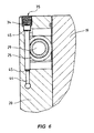
- FIG. 4 This describes, as has been previously stated, one side of an injection die where the further portion of the injection die is shown in exploded detail in FIG. 4. In this case then, there is a closed chamber 37 which surrounds a female shape 38 into which the male part 17 is located to form there between a moulding space served by inlet port 39.
- a back plate 40 has sealed engagement with the die 41 and there are shown heat exchange means at 42 with a hollow removable core 43.
- the mould temperature for instance, can be controlled very evenly and effectively by controlling the flow of coolant such as water, through the heat exchanger.
- coolant such as water
- this can be connected through a servo controller so as to interrupt flow of coolant liquid through the heat exchanger whenever the temperature falls below a selected value and can restore or increase the flow rate of cooling liquid whenever the temperature of the fluid in the enclosed chamber rises above another slightly higher selected level.
- a prototype unit has been made and tested. This unit was manufactured as the male portion of the injection die which is the arrangement as shown in FIGS. 2, 3 and 5 with a face area of 250 mm and of course the disclosed protruding core, 70 mm in diameter and 55 mm long. The enclosed chamber then had a wall thickness at the die portion of 12 mm.
Landscapes
- Engineering & Computer Science (AREA)
- Mechanical Engineering (AREA)
- Manufacturing & Machinery (AREA)
- General Engineering & Computer Science (AREA)
- Thermal Sciences (AREA)
- Chemical & Material Sciences (AREA)
- Combustion & Propulsion (AREA)
- Health & Medical Sciences (AREA)
- Physics & Mathematics (AREA)
- Oral & Maxillofacial Surgery (AREA)
- Moulds For Moulding Plastics Or The Like (AREA)
- Control Of Temperature (AREA)
- Heating, Cooling, Or Curing Plastics Or The Like In General (AREA)
- Injection Moulding Of Plastics Or The Like (AREA)
- Blow-Moulding Or Thermoforming Of Plastics Or The Like (AREA)
- Investigating Or Analyzing Materials Using Thermal Means (AREA)
- Polymers With Sulfur, Phosphorus Or Metals In The Main Chain (AREA)
- Cookers (AREA)
- Processing And Handling Of Plastics And Other Materials For Molding In General (AREA)
Claims (15)
- Form eines Typs, der erfordert, dass von Zeit zu Zeit Wärme von der Form entfernt wird, welche Form mindestens eine geschlossene Kammer (21; 37) mit darin enthaltender Flüssigkeit (22), welche sich ausbreitet, um mindestens einen der Bereiche zu bedecken, von denen Wärme zu entfernen ist, und einen Raum (23) über der Flüssigkeit (22) und innerhalb der geschlossenen Kammer (21; 37) einschließt, wobei Druck auf eine Höhe eingestellt wird, die Kochen der Flüssigkeit (22) bei einer ausgewählten Temperatur ermöglichen wird, und gekennzeichnet durch ein Kondensiermittel (25; 42), um durch Kühlen Kondensation des Dampfs oder der Dämpfe der Flüssigkeit (22) in dem Raum zu bewirken.
- Form nach Anspruch 1, bei der die Kammer (21; 37) so geformt und positioniert ist, dass die Flüssigkeit (22) darin effektiven Zugang zu jedem der Bereiche der Form haben wird, von dem Wärme zu entfernen ist.
- Form nach Anspruch 1 oder 2, welche Form eine Form zum Spritzgießen von Kunststoffmaterialien, oder eine Form zum Formgießen von Metallen ist.
- Form nach Anspruch 1 oder 2, welche Form eine Form zum Spritzgießen von Kunststoffmaterialien, oder eine Form zum Formen durch Thermoformen von Kunststoffmaterialien ist.
- Form mit einer internen Kühleinrichtung, die eine geschlossene Kammer (21; 37) ist mit einer darin enthaltenen Flüssigkeit (22) mit einem solchen Volumen, das es einen oberen Füllstand über mindestens einigen der zu kühlenden Bereiche der Form hat und im wesentlichen nur den Dampf oder die Dämpfe der Flüssigkeit (22) in einem Raum (23) innerhalb der Kammer (21; 37) über dem oberen Füllstand der Flüssigkeit aufweist, und einem Kondensiermittel (25; 42), um durch Kühlen Kondensation des Dampfs oder der Dämpfe der Flüssigkeit zu bewirken.
- Form nach einem der vorhergehenden Ansprüche, die zum Spritzgießen von Kunststoffmaterialien bestimmt ist und in der die genannte geschlossene Kammer (21; 37) teilweise mit einer Flüssigkeit (22) mit einem oberen Füllstand gefüllt ist, der ausreichend ist, damit mindestens einige der Bereiche der Form innerhalb der Kammer (21; 37) angrenzend an zu kühlende Teile der Form durch die Flüssigkeit (22) eingenommen werden, wenn die Form in Gebrauch ist, und in dem Raum (23) in der Kammer über der Flüssigkeit (22) im wesentlichen nur der Dampf der Flüssigkeit (22) und das genannte Kondensiermittel (25; 42) in diesem Raum vorliegt.
- Form nach einem der Anspruch 1 bis 5, die zum Spritzgießen von Kunststoffmaterialien bestimmt ist und in der die genannte geschlossene Kammer (21; 37) teilweise mit einer Flüssigkeit (22) mit einem oberen Füllstand ausreichender Höhe gefüllt ist, so dass mindestens einige der Bereiche der Form innerhalb der Kammer (21; 37) angrenzend an zu kühlende Teile der Form durch die Flüssigkeit (22) eingenommen werden, wenn die Form in Gebrauch ist, und in einem Raum (23) in der Kammer (21; 37) über der Flüssigkeit (22) im wesentlichen nur der Dampf der Flüssigkeit (22) und eine Einrichtung zum Liefern von Kühlung von jeglichem Dampf innerhalb des Raums (23) in der Kammer (21; 37) über dem Flüssigkeitsfüllstand vorliegt, um dadurch mindestens eine gewisse Kondensation des Dampfes zu bewirken.
- Form nach Anspruch 6 oder 7, bei der mindestens ein Erhitzungsmittel innerhalb der Kammer (21; 37) innerhalb der Flüssigkeit (22) so angeordnet ist, dass während einer Bereitschaftszeit die Temperatur des Formwerkzeugs oder der Form innerhalb eines ausgewählten Temperaturbereichs gehalten werden kann.
- Form nach einem der Ansprüche 6 bis 8, bei der das Kühlmittel (25; 42) ein Rohr, einen Kern (29) im Rohr und Mittel zum Leiten von Kühlwasser durch das Rohr einschließt.
- Form nach einem der vorhergehenden Ansprüche, bei der die Flüssigkeit (22) Wasser ist.
- Form nach einem der vorhergehenden Ansprüche, bei der die Flüssigkeit (22) nur Wasser ist.
- Form nach einem der vorhergehenden Ansprüche, bei der der Dampf Wasserdampf ist.
- Verfahren zum Kühlen von Arbeitsteilen einer Form, wobei die Form mindestens eine geschlossene Kammer (21; 37) mit darin enthaltener Flüssigkeit (22), die sich ausbreitet, um mindestens einen der Bereiche zu bedecken, von denen Wärme zu entfernen ist, und einen Raum (23) über der Flüssigkeit (22) und innerhalb der geschlossenen Kammer (21; 37) aufweist, in dem veranlasst wird, dass Druck innerhalb des Raums (23) auf eine Höhe eingestellt wird, die Kochen der Flüssigkeit (22) bei einer ausgewählten Temperatur ermöglichen wird, wobei die genannte ausgewählte Temperatur auf einer solchen Höhe ist, dass die Temperatur unter einer Temperatur des Bereichs ist, von dem Wärme zu entfernen ist, was dadurch begründet ist, dass als ein erster Schritt die geschlossenen Kammer (21; 37) teilweise mit der Flüssigkeit (22) gefüllt und dann Luft so extrahiert wird, dass im wesentlichen nur der Dampf oder die Dämpfe der Flüssigkeit (22) innerhalb der Kammer (21; 37) über dem oberen Füllstand der Flüssigkeit (22) vorliegt/vorliegen, und Flüssigkeit (22) bei einer ausgewählten Kühltemperatur durch ein Kondensiermittel (25; 42) geführt wird, um durch solches Kühlen Kondensation des Dampfes der Flüssigkeit (22) in dem Raum zu bewirken.
- Verfahren nach Anspruch 13, bei dem der genannte erste Schritt aufweist, die geschlossene Kammer (21; 37) mit der Flüssigkeit (22) zu füllen, und dann einen ausgewählten Anteil der Flüssigkeit (22) zu extrahieren, ohne zuzulassen, dass Luft die extrahierte Flüssigkeit ersetzt.
- Verfahren nach Anspruch 12 oder 13, bei dem die Flüssigkeit Wasser ist.
Applications Claiming Priority (3)
| Application Number | Priority Date | Filing Date | Title |
|---|---|---|---|
| AUPP403398 | 1998-06-11 | ||
| AUPP4033A AUPP403398A0 (en) | 1998-06-11 | 1998-06-11 | Temperature control method and apparatus |
| PCT/AU1999/000448 WO1999064218A1 (en) | 1998-06-11 | 1999-06-09 | Temperature control method and apparatus |
Publications (3)
| Publication Number | Publication Date |
|---|---|
| EP1109656A1 EP1109656A1 (de) | 2001-06-27 |
| EP1109656A4 EP1109656A4 (de) | 2003-01-22 |
| EP1109656B1 true EP1109656B1 (de) | 2005-03-30 |
Family
ID=3808278
Family Applications (1)
| Application Number | Title | Priority Date | Filing Date |
|---|---|---|---|
| EP99955453A Expired - Lifetime EP1109656B1 (de) | 1998-06-11 | 1999-06-09 | Verfahren und gerät zur kontrolle der temperatur |
Country Status (14)
| Country | Link |
|---|---|
| US (2) | US7964129B1 (de) |
| EP (1) | EP1109656B1 (de) |
| JP (1) | JP4500444B2 (de) |
| KR (1) | KR20010074506A (de) |
| CN (1) | CN100366410C (de) |
| AT (1) | ATE292001T1 (de) |
| AU (1) | AUPP403398A0 (de) |
| CA (1) | CA2334676C (de) |
| DE (1) | DE69924505T2 (de) |
| ES (1) | ES2239464T3 (de) |
| ID (1) | ID28098A (de) |
| NZ (1) | NZ508954A (de) |
| WO (1) | WO1999064218A1 (de) |
| ZA (1) | ZA200007342B (de) |
Families Citing this family (48)
| Publication number | Priority date | Publication date | Assignee | Title |
|---|---|---|---|---|
| AUPQ307799A0 (en) | 1999-09-24 | 1999-10-21 | Ritemp Pty Ltd | Improvements relating to cooling of dies |
| AUPR789701A0 (en) * | 2001-09-21 | 2001-10-18 | Varcon Holdings Pty Ltd | Method and apparatus for heat exchange |
| GB2397548B (en) * | 2003-01-25 | 2005-06-22 | Husky Injection Molding | Core cooling tube assembly |
| US7252134B2 (en) * | 2004-06-28 | 2007-08-07 | Consolidated Engineering Company, Inc. | Method and apparatus for removal of flashing and blockages from a casting |
| JP4996184B2 (ja) * | 2006-09-19 | 2012-08-08 | 東京エレクトロン株式会社 | ウエハの温度制御装置及びウエハの温度制御方法 |
| TWI404619B (zh) * | 2009-04-07 | 2013-08-11 | 私立中原大學 | Gas mold surface heating system |
| KR20120034398A (ko) * | 2010-10-01 | 2012-04-12 | 삼성전자주식회사 | 사출금형의 냉각장치 및 이를 갖는 사출금형 |
| CN102463652B (zh) * | 2010-11-18 | 2013-10-16 | 张卫军 | 水气分离式eps泡沫塑料模具 |
| WO2013082675A1 (en) * | 2011-12-09 | 2013-06-13 | Ritemp Pty Ltd | Temperature regulation improvements |
| KR101375747B1 (ko) * | 2011-12-23 | 2014-03-19 | 주식회사 포스코 | 보온 커튼 방식의 몰드 플럭스 용해로와 이를 이용한 연속 주조 방법 |
| US20130295219A1 (en) | 2012-05-02 | 2013-11-07 | Ralph Edwin Neufarth | Injection Mold Having a Simplified Evaporative Cooling System or a Simplified Cooling System with Exotic Cooling Fluids |
| JP2015512808A (ja) | 2012-02-24 | 2015-04-30 | ザ プロクター アンド ギャンブルカンパニー | 簡素化された冷却システムを有する射出成形金型 |
| US9248597B2 (en) * | 2012-04-02 | 2016-02-02 | Progressive Components International Corporation | Bubbler base |
| DE102012103674A1 (de) * | 2012-04-26 | 2013-10-31 | Deutsches Zentrum für Luft- und Raumfahrt e.V. | Formwerkzeug |
| GB2502572A (en) * | 2012-05-30 | 2013-12-04 | Kraft Foods R & D Inc | Mould with optimised heat transfer properties |
| CN104736316B (zh) * | 2012-07-31 | 2017-05-24 | 3M创新有限公司 | 包括具有热可控阵列的模具腔体表面的注塑设备和方法 |
| BR112015011681A2 (pt) | 2012-11-21 | 2017-07-11 | Imflux Inc | canal de injeção de tamanho reduzido para um sistema de molde para injeção |
| JP5726845B2 (ja) * | 2012-12-13 | 2015-06-03 | 本田技研工業株式会社 | 鋳造金型冷却装置及び鋳造金型冷却方法 |
| CN103407139B (zh) * | 2013-07-12 | 2015-12-09 | 信易电热机械有限公司 | 一种高温高压水式模具控温系统及其方法 |
| DE102013109048A1 (de) * | 2013-08-21 | 2015-02-26 | Ushio Denki Kabushiki Kaisha | Verfahren und Vorrichtung zur Kühlung von Strahlungsquellen auf Basis eines Plasmas |
| JP5991678B2 (ja) * | 2013-10-07 | 2016-09-14 | 株式会社松井製作所 | 金型冷却システム及び金型冷却方法 |
| CN105058759A (zh) * | 2015-08-07 | 2015-11-18 | 苏州华冲精密机械有限公司 | 一种高性能吸塑模具 |
| EP3344408B1 (de) * | 2015-09-02 | 2020-05-27 | Alfi S.R.L. | System zum kühlen von formen für metalle oder für metalllegierungen sowie formsatz mit dem kühlsystem und mindestens einer form |
| CN107639818B (zh) * | 2016-07-22 | 2024-07-30 | 廖晧杰 | 温控装置 |
| CH713048B1 (de) * | 2016-10-14 | 2021-12-30 | Regloplas Ag | Verfahren und Einrichtung zur Sicherstellung des Betriebes eines Kreislaufs. |
| CN106735062A (zh) * | 2016-12-23 | 2017-05-31 | 营口华润有色金属制造有限公司 | 一种用于高硅铝合金缸体的压铸模具快速冷却装置及方法 |
| CN107214323A (zh) * | 2017-07-26 | 2017-09-29 | 江苏苏高流体机械有限公司 | 一种用于铸模内铁水的冷却装置 |
| CN109093092A (zh) * | 2018-08-10 | 2018-12-28 | 徐峰 | 一种机边冷却站 |
| CN110947910B (zh) * | 2018-09-26 | 2021-10-26 | 北京中铸同方科技有限公司 | 空腔传导热式耐高温金属模具 |
| CN109895339B (zh) * | 2018-11-26 | 2024-06-21 | 苏州奥德高端装备股份有限公司 | 一种多色模注射成型高光机模温控制系统 |
| NL2022253B1 (en) * | 2018-12-20 | 2020-07-14 | What The Future Venture Capital Wtfvc B V | Mould configuration |
| AU2019410407B2 (en) | 2018-12-20 | 2024-10-24 | What The Future B.V. | Mould configuration |
| CN110076973A (zh) * | 2019-04-12 | 2019-08-02 | 安徽安缆模具有限公司 | 一种注塑模具用高效冷却装置 |
| CN110076314B (zh) * | 2019-05-17 | 2020-10-30 | 宁波图冠精密模具有限公司 | 一种可快速冷却的发动机缸体压铸模具 |
| CN110450368B (zh) * | 2019-08-21 | 2020-07-03 | 佛山市美仕达玩具有限公司 | 一种高散热注塑模具 |
| AU2020390566B2 (en) * | 2019-11-29 | 2021-12-02 | Malcolm Barry James | Fluid phase change thermal management arrangement and method |
| CN111069576B (zh) * | 2019-12-12 | 2020-07-31 | 武汉天顺汽车零部件有限公司 | 一种汽车扶手骨架自动连续成型模具 |
| CN111421794B (zh) * | 2020-06-09 | 2020-11-10 | 廊坊研领科技有限公司 | 一种泡沫餐盒生产用eps成型机 |
| CN111703040B (zh) * | 2020-06-29 | 2021-05-25 | 苏州巴涛信息科技有限公司 | 分级缓冷层式铸造辅助模具 |
| TWI757884B (zh) * | 2020-09-23 | 2022-03-11 | 大陸商漢達精密電子(昆山)有限公司 | 一種用於快速熱循環成型的加壓加熱系統及方法 |
| CN112170763B (zh) * | 2020-09-25 | 2022-06-14 | 深圳市源鑫实业发展有限公司 | 一种用于铸造超高温金属件铸造模具 |
| CN112721070B (zh) * | 2021-01-29 | 2022-12-23 | 江西理工大学 | 一种聚合物共混物水辅助注塑的温控装置 |
| CN112895360B (zh) * | 2021-02-08 | 2022-12-02 | 张策旗 | 一种大型周转箱模具的防变形冷却机构 |
| CN113001038B (zh) * | 2021-03-05 | 2022-11-25 | 赣州市恒邦金属制品有限公司 | 一种具有废屑收集功能的激光切割装置 |
| CN114769556A (zh) * | 2022-04-19 | 2022-07-22 | 吴成清 | 一种便于快速冷却的汽车后轴模具 |
| CN114801067B (zh) * | 2022-05-09 | 2023-01-17 | 开平瑞信家具配件有限公司 | 一种pp扶手注塑模具及其脱模工艺 |
| CN117066453B (zh) * | 2023-10-16 | 2023-12-19 | 普洛特(烟台)汽车科技有限公司 | 一种汽车刹车盘铸造成型处理设备 |
| CN117399593B (zh) * | 2023-11-03 | 2024-03-15 | 河北顺达铸造有限公司 | 一种高效型的球墨铸铁件的铸造方法 |
Family Cites Families (30)
| Publication number | Priority date | Publication date | Assignee | Title |
|---|---|---|---|---|
| US448861A (en) | 1891-03-24 | Hoppee and shoe foe geain dbills | ||
| DE756867C (de) | 1939-08-01 | 1953-02-23 | Ig Farbenindustrie Ag | Vorrichtung zur Regelung der Temperatur bei elektrisch beheizten Vorrichtungsteilen |
| US2292946A (en) * | 1941-01-18 | 1942-08-11 | Karig Horace Edmund | Vapor cooling system |
| DE1913579B2 (de) * | 1969-03-18 | 1972-04-20 | Fa Hermann Heye, 4962 Obernkir chen | Beeinflussung der temperatur von werkzeugen glasverarbeitender maschinen durch ein geschlossenes waermeuebertragungssystem |
| US3748866A (en) * | 1971-04-23 | 1973-07-31 | Owens Illinois Inc | Method and apparatus for chilling mold elements |
| CS180312B1 (en) * | 1975-10-24 | 1977-12-30 | Michal Kostura | Equipment for automatic temperature control of metallic casting moulds |
| DE2640676A1 (de) | 1976-01-30 | 1977-08-04 | Brunswick Corp | System zur zufuehrung von fluiden medien |
| US4208177A (en) * | 1977-12-14 | 1980-06-17 | Logic Devices, Inc. | Fluid cooling of injection molded plastic articles |
| US4197900A (en) * | 1978-03-16 | 1980-04-15 | Beizerov Semen M | Furnace for vacuum arc melting of highly reactive metals |
| US4548773A (en) | 1980-05-22 | 1985-10-22 | Massachusetts Institute Of Technology | Injection molding method |
| US4387762A (en) * | 1980-05-22 | 1983-06-14 | Massachusetts Institute Of Technology | Controllable heat transfer device |
| DE3211833C2 (de) | 1982-03-31 | 1985-09-26 | Reifenhäuser GmbH & Co Maschinenfabrik, 5210 Troisdorf | Blaskopf für die Herstellung einer Kunststoffblasfolie durch Flachlegen eines Blasfolienschlauches |
| JPS60211778A (ja) | 1984-03-14 | 1985-10-24 | Sharp Corp | 固体電解質電池 |
| US4623497A (en) | 1984-11-28 | 1986-11-18 | Application Engineering Corporation | Passive mold cooling and heating method |
| US4680001A (en) | 1984-11-28 | 1987-07-14 | Application Engineering Corporation | Passive mold cooling and heating system |
| US4690789A (en) * | 1985-03-13 | 1987-09-01 | Dart Industries Inc. | Refrigerant cooled plastic molding, method and apparatus |
| JPS62107852A (ja) | 1985-11-06 | 1987-05-19 | Fuso Light Alloys Co Ltd | 金型 |
| JPS62107853A (ja) | 1985-11-06 | 1987-05-19 | Fuso Light Alloys Co Ltd | 金型の温度制御装置 |
| US5167688A (en) * | 1988-02-04 | 1992-12-01 | Guillermo Cavazos | Apparatus for mold cooling |
| SU1565709A2 (ru) | 1988-08-18 | 1990-05-23 | Тамбовское Научно-Производственное Объединение Полимерного Машиностроения | Устройство дл охлаждени перерабатываемого в черв чной машине полимерного материала |
| FR2642156B1 (fr) * | 1989-01-20 | 1994-05-20 | Bertin Et Cie | Procede et dispositif de regulation rapide d'une temperature de paroi |
| DE4033677A1 (de) | 1990-10-23 | 1992-04-30 | Metzeler Gimetall Ag | Verfahren zur konstanthaltung der temperatur in der duese einer transfer-presse |
| US5516470A (en) * | 1991-03-05 | 1996-05-14 | Aga Aktiebolag | Method of tempering a molding tool |
| US5289869A (en) * | 1992-12-17 | 1994-03-01 | Klein John F | Closed loop feedback control variable conductance heat pipe |
| US6073683A (en) * | 1995-07-05 | 2000-06-13 | Nippondenso Co., Ltd. | Cooling apparatus using boiling and condensing refrigerant and method for manufacturing the same |
| US6104611A (en) * | 1995-10-05 | 2000-08-15 | Nortel Networks Corporation | Packaging system for thermally controlling the temperature of electronic equipment |
| SE504872C2 (sv) * | 1995-10-24 | 1997-05-20 | Aga Ab | Sätt och anordning för kylning av verktyg, arbetsstycken eller liknande med kondenserad gas |
| DE19613558A1 (de) * | 1996-04-04 | 1997-10-09 | Bielsteiner Verschlustechnik G | Formwerkzeug |
| SE9604592L (sv) | 1996-12-13 | 1998-02-02 | Aga Ab | Sätt och anordning för kylning av ett formningsverktyg med kondenserad gas |
| SG64996A1 (en) * | 1997-07-08 | 1999-05-25 | Dso National Laborataries | A heat sink |
-
1998
- 1998-06-11 AU AUPP4033A patent/AUPP403398A0/en not_active Abandoned
-
1999
- 1999-06-09 ES ES99955453T patent/ES2239464T3/es not_active Expired - Lifetime
- 1999-06-09 KR KR1020007014071A patent/KR20010074506A/ko not_active Withdrawn
- 1999-06-09 JP JP2000553259A patent/JP4500444B2/ja not_active Expired - Fee Related
- 1999-06-09 CN CNB998072133A patent/CN100366410C/zh not_active Expired - Fee Related
- 1999-06-09 DE DE69924505T patent/DE69924505T2/de not_active Expired - Lifetime
- 1999-06-09 EP EP99955453A patent/EP1109656B1/de not_active Expired - Lifetime
- 1999-06-09 AT AT99955453T patent/ATE292001T1/de not_active IP Right Cessation
- 1999-06-09 CA CA002334676A patent/CA2334676C/en not_active Expired - Fee Related
- 1999-06-09 US US09/719,136 patent/US7964129B1/en not_active Expired - Fee Related
- 1999-06-09 ID IDW20010068A patent/ID28098A/id unknown
- 1999-06-09 WO PCT/AU1999/000448 patent/WO1999064218A1/en not_active Ceased
- 1999-06-09 NZ NZ508954A patent/NZ508954A/xx not_active IP Right Cessation
-
2000
- 2000-12-11 ZA ZA200007342A patent/ZA200007342B/en unknown
-
2011
- 2011-06-09 US US13/157,197 patent/US20110232856A1/en not_active Abandoned
Also Published As
| Publication number | Publication date |
|---|---|
| DE69924505T2 (de) | 2006-02-16 |
| WO1999064218A1 (en) | 1999-12-16 |
| EP1109656A4 (de) | 2003-01-22 |
| CA2334676A1 (en) | 1999-12-16 |
| DE69924505D1 (de) | 2005-05-04 |
| EP1109656A1 (de) | 2001-06-27 |
| HK1038332A1 (en) | 2002-03-15 |
| ID28098A (id) | 2001-05-03 |
| ATE292001T1 (de) | 2005-04-15 |
| KR20010074506A (ko) | 2001-08-04 |
| CN1319043A (zh) | 2001-10-24 |
| CN100366410C (zh) | 2008-02-06 |
| NZ508954A (en) | 2002-10-25 |
| US20110232856A1 (en) | 2011-09-29 |
| JP2002517330A (ja) | 2002-06-18 |
| JP4500444B2 (ja) | 2010-07-14 |
| AUPP403398A0 (en) | 1998-07-02 |
| US7964129B1 (en) | 2011-06-21 |
| ZA200007342B (en) | 2001-06-05 |
| CA2334676C (en) | 2008-08-12 |
| ES2239464T3 (es) | 2005-09-16 |
Similar Documents
| Publication | Publication Date | Title |
|---|---|---|
| EP1109656B1 (de) | Verfahren und gerät zur kontrolle der temperatur | |
| JP2007125894A (ja) | ブロー成形用金型装置 | |
| US4140512A (en) | Liquid cooling system for glass forming apparatus | |
| CN104114345B (zh) | 温度调节改进 | |
| JP2010000784A (ja) | 金型の急速加熱方法 | |
| US20060088622A1 (en) | Device and mold for rotational molding of plastic materials | |
| WO2012077779A1 (ja) | 金型冷却装置及びこれを備えた金型冷却システム | |
| CN206405411U (zh) | 一种铝合金车门压铸装置 | |
| JP4421318B2 (ja) | 金型温度調整装置、それに使用される熱回収タンク及び温度調整方法 | |
| AU746438B2 (en) | Temperature control method and apparatus | |
| HK1038332B (en) | Temperature control method and apparatus | |
| JPH0474620A (ja) | 低圧射出成形用金型 | |
| CN206646139U (zh) | 一种金属锻材的热处理装置 | |
| US11975462B2 (en) | Cooling system for moulds | |
| KR101647718B1 (ko) | 후육사출제품 치수안정화장치 | |
| JPH05337997A (ja) | プラスチック成形用金型の冷却装置 | |
| JP2006015602A (ja) | 金型温度調整装置 | |
| CN214926829U (zh) | 一种注塑模具温度控制装置 | |
| CN221209848U (zh) | 一种金属材料成型模具用冷却结构 | |
| CN219099224U (zh) | 一种热作模具钢退火装置 | |
| CN216526909U (zh) | 一种3d模具专用温度控制机 | |
| CN222681686U (zh) | 一种风冷式模温机 | |
| CN220093016U (zh) | 一种铸造铸件快速冷却装置 | |
| CN212191176U (zh) | 一种铝工件压铸模具的散热结构 | |
| CN214605437U (zh) | 一种塑料容器加工水循环冷却装置 |
Legal Events
| Date | Code | Title | Description |
|---|---|---|---|
| PUAI | Public reference made under article 153(3) epc to a published international application that has entered the european phase |
Free format text: ORIGINAL CODE: 0009012 |
|
| 17P | Request for examination filed |
Effective date: 20010109 |
|
| AK | Designated contracting states |
Kind code of ref document: A1 Designated state(s): AT BE CH CY DE DK ES FI FR GB GR IE IT LI LU MC NL PT SE |
|
| A4 | Supplementary search report drawn up and despatched |
Effective date: 20021210 |
|
| AK | Designated contracting states |
Kind code of ref document: A4 Designated state(s): AT BE CH CY DE DK ES FI FR GB GR IE IT LI LU MC NL PT SE |
|
| RIC1 | Information provided on ipc code assigned before grant |
Free format text: 7B 29C 33/04 A, 7B 29C 45/73 B, 7B 29C 45/74 B, 7B 29C 51/42 B, 7B 21C 29/04 B, 7B 22C 9/00 B, 7F 01P 3/22 B, 7B 29C 35/00 B |
|
| 17Q | First examination report despatched |
Effective date: 20030318 |
|
| GRAP | Despatch of communication of intention to grant a patent |
Free format text: ORIGINAL CODE: EPIDOSNIGR1 |
|
| RIN1 | Information on inventor provided before grant (corrected) |
Inventor name: JAMES, MALCOLM BARRY |
|
| GRAS | Grant fee paid |
Free format text: ORIGINAL CODE: EPIDOSNIGR3 |
|
| GRAA | (expected) grant |
Free format text: ORIGINAL CODE: 0009210 |
|
| AK | Designated contracting states |
Kind code of ref document: B1 Designated state(s): AT BE CH CY DE DK ES FI FR GB GR IE IT LI LU MC NL PT SE |
|
| PG25 | Lapsed in a contracting state [announced via postgrant information from national office to epo] |
Ref country code: NL Free format text: LAPSE BECAUSE OF FAILURE TO SUBMIT A TRANSLATION OF THE DESCRIPTION OR TO PAY THE FEE WITHIN THE PRESCRIBED TIME-LIMIT Effective date: 20050330 Ref country code: FI Free format text: LAPSE BECAUSE OF FAILURE TO SUBMIT A TRANSLATION OF THE DESCRIPTION OR TO PAY THE FEE WITHIN THE PRESCRIBED TIME-LIMIT Effective date: 20050330 Ref country code: BE Free format text: LAPSE BECAUSE OF FAILURE TO SUBMIT A TRANSLATION OF THE DESCRIPTION OR TO PAY THE FEE WITHIN THE PRESCRIBED TIME-LIMIT Effective date: 20050330 Ref country code: AT Free format text: LAPSE BECAUSE OF FAILURE TO SUBMIT A TRANSLATION OF THE DESCRIPTION OR TO PAY THE FEE WITHIN THE PRESCRIBED TIME-LIMIT Effective date: 20050330 |
|
| REG | Reference to a national code |
Ref country code: GB Ref legal event code: FG4D |
|
| REG | Reference to a national code |
Ref country code: CH Ref legal event code: EP |
|
| REF | Corresponds to: |
Ref document number: 69924505 Country of ref document: DE Date of ref document: 20050504 Kind code of ref document: P |
|
| REG | Reference to a national code |
Ref country code: IE Ref legal event code: FG4D |
|
| REG | Reference to a national code |
Ref country code: CH Ref legal event code: NV Representative=s name: ISLER & PEDRAZZINI AG |
|
| PG25 | Lapsed in a contracting state [announced via postgrant information from national office to epo] |
Ref country code: LU Free format text: LAPSE BECAUSE OF NON-PAYMENT OF DUE FEES Effective date: 20050609 Ref country code: CY Free format text: LAPSE BECAUSE OF FAILURE TO SUBMIT A TRANSLATION OF THE DESCRIPTION OR TO PAY THE FEE WITHIN THE PRESCRIBED TIME-LIMIT Effective date: 20050609 |
|
| REG | Reference to a national code |
Ref country code: HK Ref legal event code: GR Ref document number: 1038332 Country of ref document: HK |
|
| PG25 | Lapsed in a contracting state [announced via postgrant information from national office to epo] |
Ref country code: MC Free format text: LAPSE BECAUSE OF NON-PAYMENT OF DUE FEES Effective date: 20050630 Ref country code: GR Free format text: LAPSE BECAUSE OF FAILURE TO SUBMIT A TRANSLATION OF THE DESCRIPTION OR TO PAY THE FEE WITHIN THE PRESCRIBED TIME-LIMIT Effective date: 20050630 Ref country code: DK Free format text: LAPSE BECAUSE OF FAILURE TO SUBMIT A TRANSLATION OF THE DESCRIPTION OR TO PAY THE FEE WITHIN THE PRESCRIBED TIME-LIMIT Effective date: 20050630 |
|
| PG25 | Lapsed in a contracting state [announced via postgrant information from national office to epo] |
Ref country code: PT Free format text: LAPSE BECAUSE OF FAILURE TO SUBMIT A TRANSLATION OF THE DESCRIPTION OR TO PAY THE FEE WITHIN THE PRESCRIBED TIME-LIMIT Effective date: 20050907 |
|
| REG | Reference to a national code |
Ref country code: ES Ref legal event code: FG2A Ref document number: 2239464 Country of ref document: ES Kind code of ref document: T3 |
|
| NLV1 | Nl: lapsed or annulled due to failure to fulfill the requirements of art. 29p and 29m of the patents act | ||
| REG | Reference to a national code |
Ref country code: SE Ref legal event code: TRGR |
|
| PLBE | No opposition filed within time limit |
Free format text: ORIGINAL CODE: 0009261 |
|
| STAA | Information on the status of an ep patent application or granted ep patent |
Free format text: STATUS: NO OPPOSITION FILED WITHIN TIME LIMIT |
|
| ET | Fr: translation filed | ||
| 26N | No opposition filed |
Effective date: 20060102 |
|
| REG | Reference to a national code |
Ref country code: CH Ref legal event code: PCAR Free format text: ISLER & PEDRAZZINI AG;POSTFACH 1772;8027 ZUERICH (CH) |
|
| PG25 | Lapsed in a contracting state [announced via postgrant information from national office to epo] |
Ref country code: SE Free format text: LAPSE BECAUSE OF FAILURE TO SUBMIT A TRANSLATION OF THE DESCRIPTION OR TO PAY THE FEE WITHIN THE PRESCRIBED TIME-LIMIT Effective date: 20050630 |
|
| PGRI | Patent reinstated in contracting state [announced from national office to epo] |
Ref country code: SE Effective date: 20051215 |
|
| PGFP | Annual fee paid to national office [announced via postgrant information from national office to epo] |
Ref country code: SE Payment date: 20150611 Year of fee payment: 17 Ref country code: ES Payment date: 20150527 Year of fee payment: 17 Ref country code: CH Payment date: 20150612 Year of fee payment: 17 |
|
| PGFP | Annual fee paid to national office [announced via postgrant information from national office to epo] |
Ref country code: IE Payment date: 20150609 Year of fee payment: 17 |
|
| PGFP | Annual fee paid to national office [announced via postgrant information from national office to epo] |
Ref country code: IT Payment date: 20150625 Year of fee payment: 17 |
|
| REG | Reference to a national code |
Ref country code: FR Ref legal event code: PLFP Year of fee payment: 18 |
|
| PGFP | Annual fee paid to national office [announced via postgrant information from national office to epo] |
Ref country code: DE Payment date: 20160616 Year of fee payment: 18 Ref country code: GB Payment date: 20160608 Year of fee payment: 18 |
|
| PGFP | Annual fee paid to national office [announced via postgrant information from national office to epo] |
Ref country code: FR Payment date: 20160630 Year of fee payment: 18 |
|
| REG | Reference to a national code |
Ref country code: CH Ref legal event code: PL Ref country code: SE Ref legal event code: EUG |
|
| PG25 | Lapsed in a contracting state [announced via postgrant information from national office to epo] |
Ref country code: SE Free format text: LAPSE BECAUSE OF FAILURE TO SUBMIT A TRANSLATION OF THE DESCRIPTION OR TO PAY THE FEE WITHIN THE PRESCRIBED TIME-LIMIT Effective date: 20160610 |
|
| REG | Reference to a national code |
Ref country code: IE Ref legal event code: MM4A |
|
| PG25 | Lapsed in a contracting state [announced via postgrant information from national office to epo] |
Ref country code: LI Free format text: LAPSE BECAUSE OF NON-PAYMENT OF DUE FEES Effective date: 20160630 Ref country code: CH Free format text: LAPSE BECAUSE OF NON-PAYMENT OF DUE FEES Effective date: 20160630 |
|
| PG25 | Lapsed in a contracting state [announced via postgrant information from national office to epo] |
Ref country code: IE Free format text: LAPSE BECAUSE OF NON-PAYMENT OF DUE FEES Effective date: 20160609 |
|
| PG25 | Lapsed in a contracting state [announced via postgrant information from national office to epo] |
Ref country code: IT Free format text: LAPSE BECAUSE OF NON-PAYMENT OF DUE FEES Effective date: 20160609 |
|
| REG | Reference to a national code |
Ref country code: DE Ref legal event code: R119 Ref document number: 69924505 Country of ref document: DE |
|
| GBPC | Gb: european patent ceased through non-payment of renewal fee |
Effective date: 20170609 |
|
| REG | Reference to a national code |
Ref country code: FR Ref legal event code: ST Effective date: 20180228 |
|
| PG25 | Lapsed in a contracting state [announced via postgrant information from national office to epo] |
Ref country code: GB Free format text: LAPSE BECAUSE OF NON-PAYMENT OF DUE FEES Effective date: 20170609 Ref country code: DE Free format text: LAPSE BECAUSE OF NON-PAYMENT OF DUE FEES Effective date: 20180103 |
|
| REG | Reference to a national code |
Ref country code: ES Ref legal event code: FD2A Effective date: 20180507 |
|
| PG25 | Lapsed in a contracting state [announced via postgrant information from national office to epo] |
Ref country code: ES Free format text: LAPSE BECAUSE OF NON-PAYMENT OF DUE FEES Effective date: 20160610 Ref country code: FR Free format text: LAPSE BECAUSE OF NON-PAYMENT OF DUE FEES Effective date: 20170630 |