EP1109689B1 - Heizungs- und klimaanlage mit einer luftmischklappe - Google Patents
Heizungs- und klimaanlage mit einer luftmischklappe Download PDFInfo
- Publication number
- EP1109689B1 EP1109689B1 EP00949671A EP00949671A EP1109689B1 EP 1109689 B1 EP1109689 B1 EP 1109689B1 EP 00949671 A EP00949671 A EP 00949671A EP 00949671 A EP00949671 A EP 00949671A EP 1109689 B1 EP1109689 B1 EP 1109689B1
- Authority
- EP
- European Patent Office
- Prior art keywords
- flap
- air
- installation according
- region
- axis
- Prior art date
- Legal status (The legal status is an assumption and is not a legal conclusion. Google has not performed a legal analysis and makes no representation as to the accuracy of the status listed.)
- Expired - Lifetime
Links
Images



Classifications
-
- B—PERFORMING OPERATIONS; TRANSPORTING
- B60—VEHICLES IN GENERAL
- B60H—ARRANGEMENTS OF HEATING, COOLING, VENTILATING OR OTHER AIR-TREATING DEVICES SPECIALLY ADAPTED FOR PASSENGER OR GOODS SPACES OF VEHICLES
- B60H1/00—Heating, cooling or ventilating devices
- B60H1/00007—Combined heating, ventilating, or cooling devices
- B60H1/00021—Air flow details of HVAC devices
- B60H1/00035—Air flow details of HVAC devices for sending an air stream of uniform temperature into the passenger compartment
-
- B—PERFORMING OPERATIONS; TRANSPORTING
- B60—VEHICLES IN GENERAL
- B60H—ARRANGEMENTS OF HEATING, COOLING, VENTILATING OR OTHER AIR-TREATING DEVICES SPECIALLY ADAPTED FOR PASSENGER OR GOODS SPACES OF VEHICLES
- B60H1/00—Heating, cooling or ventilating devices
- B60H1/00007—Combined heating, ventilating, or cooling devices
- B60H1/00021—Air flow details of HVAC devices
- B60H1/00064—Air flow details of HVAC devices for sending air streams of different temperatures into the passenger compartment
-
- B—PERFORMING OPERATIONS; TRANSPORTING
- B60—VEHICLES IN GENERAL
- B60H—ARRANGEMENTS OF HEATING, COOLING, VENTILATING OR OTHER AIR-TREATING DEVICES SPECIALLY ADAPTED FOR PASSENGER OR GOODS SPACES OF VEHICLES
- B60H1/00—Heating, cooling or ventilating devices
- B60H1/00642—Control systems or circuits; Control members or indication devices for heating, cooling or ventilating devices
- B60H1/00664—Construction or arrangement of damper doors
- B60H1/00671—Damper doors moved by rotation; Grilles
-
- B—PERFORMING OPERATIONS; TRANSPORTING
- B60—VEHICLES IN GENERAL
- B60H—ARRANGEMENTS OF HEATING, COOLING, VENTILATING OR OTHER AIR-TREATING DEVICES SPECIALLY ADAPTED FOR PASSENGER OR GOODS SPACES OF VEHICLES
- B60H1/00—Heating, cooling or ventilating devices
- B60H1/00007—Combined heating, ventilating, or cooling devices
- B60H1/00021—Air flow details of HVAC devices
- B60H2001/00078—Assembling, manufacturing or layout details
- B60H2001/00092—Assembling, manufacturing or layout details of air deflecting or air directing means inside the device
-
- B—PERFORMING OPERATIONS; TRANSPORTING
- B60—VEHICLES IN GENERAL
- B60H—ARRANGEMENTS OF HEATING, COOLING, VENTILATING OR OTHER AIR-TREATING DEVICES SPECIALLY ADAPTED FOR PASSENGER OR GOODS SPACES OF VEHICLES
- B60H1/00—Heating, cooling or ventilating devices
- B60H1/00007—Combined heating, ventilating, or cooling devices
- B60H1/00021—Air flow details of HVAC devices
- B60H2001/00078—Assembling, manufacturing or layout details
- B60H2001/00107—Assembling, manufacturing or layout details characterised by the relative position of the heat exchangers, e.g. arrangements leading to a curved airflow
-
- B—PERFORMING OPERATIONS; TRANSPORTING
- B60—VEHICLES IN GENERAL
- B60H—ARRANGEMENTS OF HEATING, COOLING, VENTILATING OR OTHER AIR-TREATING DEVICES SPECIALLY ADAPTED FOR PASSENGER OR GOODS SPACES OF VEHICLES
- B60H1/00—Heating, cooling or ventilating devices
- B60H1/00642—Control systems or circuits; Control members or indication devices for heating, cooling or ventilating devices
- B60H1/00664—Construction or arrangement of damper doors
- B60H2001/00721—Air deflecting or air directing means
Definitions
- the subject of the present invention is a heating installation and in particular heating-air conditioning including in particular an air inlet, optionally provided with an evaporator through which air from the air inlet, and a member radiator, as well as a movable mixing flap between first and second extreme positions, the first position corresponding to a direct passage of the air coming from the air inlet, after crossing optionally said evaporator, to a circuit of air distribution to form a direct air flow, the second position corresponding to a passage derived from air from the air inlet through an opening which supplies the radiator element, before reach the air distribution circuit through a bypass channel located downstream of the forming element radiator to constitute a flow of derived air, intermediate positions between the first and second position allowing mixing between said air flow direct and said flow of derived air.
- the direct air flow As well as the derived air flow, are generally supplied from of air coming from the air inlet and coming out of the evaporator.
- the mixing component is of the butterfly type and it is articulated around a supported axis by one end of a dividing wall located between the radiator element and the distribution channel.
- a first part of the shutter blocks the air bypass towards the radiator element, while a second part of the shutter blocks the outlet of the distribution.
- the first portion of the shutter blocks the direct passage of air so that the air flow from the air inlet (and possibly from the evaporator) is derived fully towards the radiator element while the second part of the shutter completely clears the exit distribution channel.
- the opening of the flap allows achieve the desired mix between direct air flow and the flow of air diverted through the forming element radiator.
- the subject of the present invention is a heating installation and in particular heating-air conditioning presenting a mix on the air, and for which the cross section of the direct air flow does not no longer exhibits the above limitation.
- the installation is thus characterized in that the mixing flap has an axis of rotation disposed in the vicinity of an edge of the bypass channel which is opposite to the air intake, and presents a first and a second adjacent regions, in that in the first position, the first region closes said supply opening of the radiator element and the second region at least partially blocks said bypass channel, and in that in the second position, the first and second regions cooperate to close a direct passage opening to the air distribution circuit.
- At least one of said first and second regions can be flat.
- the first region can be flat and the second region can present a curvilinear profile which turns its concavity towards said branch canal, the profile of the second region being for example, at least in part an arc of circle.
- the second region is profiled so as to allow a air passage from the air inlet to the distribution in at least some positions intermediaries between the first and second position of the mixing panel.
- the second region can have abutting regions at its ends sealing between which a region is arranged re-entering towards the bypass channel, for allow said passage of air to the distribution.
- the first region may have a curvilinear profile turning its concavity towards said air inlet (when the mixing flap is in its second position) and the second region may have a curvilinear profile turning its concavity towards said bypass channel (when the mixing panel is in its second position), to allow said passage of air to the distribution channel.
- This controlled admission of air into the bypass channel allows, by creating so controlled partial mixing upstream of the distribution, improve the mix between the air flow direct and bypass air flow, and avoid at least partially the phenomena encountered with devices of the prior art, in particular the stratification.
- the device according to the invention can also present a means for directing the air flow derived from so as to facilitate mixing with the direct air flow in at least one intermediate position of the shutter mixing.
- This means of orientation can be for example a deflector integral with the flap extending from its axis of rotation.
- the axis of rotation is the same as that of the shutter mixing or is offset from that of the shutter mixing.
- the second part can be of the flag type.
- This flag-type flap can have positions extremes such as the end of the second flap which is opposite its axis of rotation constitutes, when said flap is in the first position, a trailing edge or according to another variant, a leading edge for the derived air flow passing through it.
- the second part can be of the butterfly type or even of the drum type.
- the axis of the second drum type flap can be arranged either upstream of the axis of the mixing flap in the direction of propagation of the derived air flow, either downstream of it.
- the description below relates to a heating-air conditioning system which has a refrigerant loop and therefore an evaporator, crossed by air from the air inlet. Note that the invention also applies to an installation of heating, without refrigerant loop, and therefore evaporator, and which presents a mixture between air from the air inlet (direct flow) and a flow derivative which passes through a radiator element.
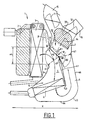
- the device shown in Figure 1, and designated by the general reference 1 has an entry air 2, axial or lateral, from which the air passes through an evaporator 3 to generate air fresh which is then sent to the passenger compartment of the vehicle.
- the air that leaves of evaporator 3 can be directed directly under as a direct flow to a distribution channel air which can include for example a defrost 15 and an air duct 16, of which the supply is controlled by butterfly valves 11 and 12 respectively.
- Another butterfly valve 14 can be implemented to direct the air to an outlet 33 for heating the feet of vehicle passengers.
- the prior art facilities employ a so-called air mixing flap 8 which is articulated around a axis 80 located at one end 42 of a separating partition 41 of the branch circuit.
- This butterfly valve has two portions or flaps 81 and 82 and is movable between two extreme positions I and II.
- portion 81 of the flap 8 closes the circuit of bypass and portion 82 blocks the outlet of channel 6 bypass located downstream of element 4 forming radiator.
- the abutment regions 9 ′ and 31 are carried by a wall 9, of curvilinear contour for example, which forms a narrowing of the air passage at the outlet of the evaporator 3. They are separated by a distance ⁇ 1 which is relatively small due to the geometry of the device and possible travel of the type shutter butterfly.
- the distance ⁇ 2 between the axis 80 of the flap and the stop region 31 is limited by the size of the portion 81 of the flap 80, which is necessarily reduced due to the middle position of this axis.
- the cold air from the evaporator is directed into a bypass channel 10 which has a channel 5 region located upstream of the radiator 4, and after bypass in edges 44 and 45 the bypass air flow returns approximately 180 ° in the downstream bypass channel 6 and the flap portion. 82.
- the adjustment of the position of the flap 80 between positions I and II allows you to vary the proportion between the air flow that passes directly from the evaporator 3 to the distribution circuit and the flow of air diverted and heated by the radiator 4.
- the mixture between the direct air flow and the air flow derivative takes place in a mixing chamber 32 located at level of the distribution circuit, upstream of the outlets (15, 16, 33).
- a first problem posed by this installation is the limitation of the value of ⁇ 1 and ⁇ 2.
- Another problem with this device of the prior art is an inhomogeneous mixture in the mixing chamber 32 of the distribution channel which is located immediately in downstream of the flap 80, which results in particular in a stratification of the air which remains composed of layers hot and cold instead of being distributed in the form an air flow of uniform temperature.
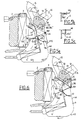
- a first variant of a device according to the invention has a flap 100 whose axis of rotation 101 is located at near the wall 46 of the opposite branch canal 6 evaporator 3.
- This shutter 100 presents, in the mode of proposed realization, a first region 102 which is plane and which is coplanar with the axis of rotation 101, and a second region 103 forming an arc of a circle adjacent to region 102 and which, at its point of departure 105 has a tangent perpendicular to the plane of the plane region 102.
- Regions 102 and 103 are connected to the axis 101 by a rod or a flat region 104.
- position I clears a large space for the passage of the direct flow leaving the evaporator 3 since the ⁇ 1 coast depends on the angular beats of the part 100 which is improved on the one hand by the fact that the axis 101 is no longer median but located in the vicinity of the wall 46, and secondly by the fact that the arrangement shutter 103 is more favorable for travel important angles.
- the layout of the flap 100 fully clears the ⁇ 2 rib in position I. This significant increase in the ⁇ 1 and ⁇ 2 coasts allows significantly reduce pressure losses for direct air flow, and increase the volume mixing chamber staff 32.
- the end 106 of the flap 103 moves gradually to more or less seal the canal distribution 106 and therefore influence the amount of air derivative which is mixed with the direct air flow. This mixture is more or less modulated also by the position of the flap 102 which comes more or less interpose and divide the air flow leaving the evaporator 3.
- the embodiment of Figure 3 is distinguishes by the fact that the rod 104 presents at its birth a region 105 forming a small flap which comes divert the flow leaving channel 6 towards the flow direct from evaporator 3, so as to facilitate mixing between these two streams in mixing chamber 32 and at least partially avoid the phenomenon of stratification mentioned above.
- the flap 100 ' has a second region 103 'profiled so as to present a stop region 108 for position I, a region of stop 109 for position II, while region 107 located between these two stops is set back towards of the wall 46, that is to say opposite of the air flow from evaporator 3 so that in the positions shutter intermediates 100 ', part of the air leaving of evaporator 3 passes between region 107 and region of curved stopper 48 and is introduced directly into the downstream diversion channel 6 where it mixes with the flow derived air leaving the radiator 4.
- the embodiment shown in the figures 5a to 5c is a variant of the previous one. It stands out by the shape of the flap 110, which is an inverted S (on the drawing) presenting a first region 111 whose concavity is facing evaporate 3, a point inflection 112, and a second region 114 whose concavity is turned towards the axis of rotation 101 located at near the wall 46.
- the end 116 serves as a stop at 9 'from position I and at 31 for position II.
- the end 115 serves as a stop at 48 for position II (shown in solid lines).
- the S-profile gradually emerges and more and more space between the component and the region 48 as the flap 110 rotates in the direction counterclockwise (such as represented).
- Section 110 presenting a first region 11 and a second region 114 is connected to the axis 101 by a plane region 104 ′ (FIG. 5b) which can be offset towards the inside of channel 6 as shown in the figure 5c (item 104 '').
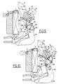
- the flap 100 is substantially represented as in Figures 2 and 3, and the function of redirecting the air leaving the distribution channel 6 is carried out not in a region such as 105 of flap 100, but by a second flap 120, of the flag type, movable between two positions I where the flap 120 runs along a region 50 of the wall 46 located downstream of axis 101 and a position II, in which, it comes for example in alignment with region 102 of the flap 100. It is thus possible to adjust the position of this second shutter 120 to obtain the best efficiency mixing the direct flow and the derivative flow.
- the flap 130 is of the articulated flag type around axis 101 but in position I it comes go along a region 130 of the wall 46 located upstream of axis 101.
- the orientation of the air coming from the bypass channel 6 is provided by a flap 140 of type butterfly whose axis 141 is located in a region median of channel 6, for example, as shown, in the plan of region 102 of shutter 100 in position I.
- a flap 140 of type butterfly In position I of the second flap 140, it is substantially parallel to the axis of channel 6 while it just close it in position II.
- the second part is drum type.
- its axis 151 is located at upstream of the axis 101, and, in its position I, the flap 150 is housed in a concave region 152 of the wall 46 located upstream of axis 101.
- the flap 150 closes the outlet of channel 6.
- axis 161 of flap 160 of drum type is located downstream of axis 101 and in its position I, it is housed in a concave region 162 of the wall 46 located downstream of the axis 101.
- the flap 162 closes the outlet of channel 6.
- An advantage of the second component, described in relationship with Figures 6 to 10 is that in "cold" mode (passage of the only direct flow), it can be in position closed, which allows the hollow 103 of the shutter to be closed mixing, which is likely to generate vortexes.
- the axis 101 of the shutter mixing could be set aside significantly of the wall 46, so as in particular to allow passage, between this axis 101 and the wall 46, part of the flow derivative, to mixing chamber 32.
- the installation according to the invention can be integrated into a driving position of a motor vehicle.
Landscapes
- Physics & Mathematics (AREA)
- Thermal Sciences (AREA)
- Engineering & Computer Science (AREA)
- Mechanical Engineering (AREA)
- Air-Conditioning For Vehicles (AREA)
- Air-Flow Control Members (AREA)
- Multiple-Way Valves (AREA)
Claims (21)
- Klimagerät, insbesondere Heizklimagerät, umfassend insbesondere einen Lufteintritt (2), ein Heizkörper (4) bildendes Element und eine Mischklappe (100, 100', 110), die zwischen ersten (I) und zweiten (II) Extrempositionen versetzbar ist, wobei die erste Position einem direkten Durchtritt der Luft von dem Lufteintritt (2) hin zu einem Luftverteilerkreis entspricht, um eine direkte Luftströmung zu bilden, und wobei die zweite Position einem umgelenkten Durchtritt der Luft von dem Lufteintritt durch eine Öffnung entspricht, welche das Heizkörper (4) bildende Element versorgt, bevor sie den Luftverteilerkreis durch einen Umlenkkanal (6) erreicht, der flußabwärtsliegend des Heizkörper (4) bildenden Elementes angeordnet ist, um eine umgelenkte Luftströmung zu bilden, wobei zwischengelagerte Positionen zwischen der ersten und der zweiten Position eine Mischung zwischen der direkten Luftströmung und der umgelenkten Luftströmung ermöglichen, dadurch gekennzeichnet, daß die Mischklappe (100, 100', 110) eine Rotationsachse 101 aufweist, die benachbart einem Rand (46) des Umlenkkanales (6) angeordnet ist, gegenüberliegend dem Lufteintritt, und erste (102, 111) und zweite (103, 103', 114) benachbarte Bereiche aufweist, daß in der ersten Position (I) der erste Abschnitt (102, 111) die Öffnung zur Versorgung des Heizkörper bildenden Elementes (4) sperrt, wobei der zweite Abschnitt (103, 103', 112) zumindest teilweise den Umlenkkanal (6) sperrt, und daß in der zweiten Position (II) die ersten (102, 111) und zweiten (103, 103', 114) Bereiche zusammenwirken, um eine Öffnung des direkten Durchtrittes hin zu dem Luftverteilerkreis (15, 16, 33) zu sperren.
- Gerät nach Anspruch 1, dadurch gekennzeichnet, daß zumindest einer der ersten (102) und zweiten (103) Bereiche eben ist.
- Gerät nach Anspruch 2, dadurch gekennzeichnet, daß der erste Abschnitt (102) eben ist, und daß der zweite Abschnitt (103) ein kurvenartiges Profil aufweist, welches eine Krümmung hin zu dem Umlenkkanal (6) aufweist oder dreht.
- Gerät nach Anspruch 3, dadurch gekennzeichnet, daß das Profil des zweiten Bereiches (103) zumindest teilweise ein Kreisbogen ist.
- Gerät nach einem der vorangegangenen Ansprüche, dadurch gekennzeichnet, daß der zweite Abschnitt (103', 114) in solch einer Weise profiliert ist, daß ein Luftdurchtritt von dem Lufteintritt hin zu dem Verteilerkanal (6) in zumindest bestimmten zwischengelagerten Positionen zwischen der ersten Position (I) und der zweiten Position (II) möglich ist.
- Gerät nach Anspruch 5, dadurch gekennzeichnet, daß der zweite Abschnitt oder Bereich an seinen Enden Bereiche (108, 109) aufweist, die Dichtungsanschläge bilden, zwischen welchen ein Bereich (107) angeordnet ist, der sich in Richtung des Umlenkkanales (6) erstreckt, um den Luftdurchtritt hin zu dem Verteilerkanal zu ermöglichen.
- Gerät nach Anspruch 5, dadurch gekennzeichnet, daß die Mischklappe (110) einen ersten Bereich (111) mit einem kurvenartigen Profil aufweist, dessen Krümmung hin zu dem Lufteintritt (2) gerichtet oder gedreht ist, wenn die Mischklappe (110) in ihrer zweiten Position (II) vorliegt, sowie einen zweiten Bereich (114) mit einem kurvenartigen Profil, dessen Krümmung hin zu dem Umlenkkanal (6) gerichtet oder gedreht ist, wenn die Mischklappe (110) in ihrer zweiten Position (II) vorliegt.
- Gerät nach einem der vorangegangenen Ansprüche, dadurch gekennzeichnet, daß ein Verdampfer (3) vorgesehen ist, der von Luft durchquert wird, welche von dem Lufteintritt herrührt.
- Gerät nach einem der vorangegangenen Ansprüche, dadurch gekennzeichnet, daß eine Einrichtung (105, 120, 130, 140, 150, 160) vorgesehen ist, um die umgelenkte Luftströmung in solch einer Weise auszurichten, daß deren Mischung mit der direkten Luftströmung in zumindest einer zwischengelagerten Position der Mischklappe (100, 100', 110) vereinfacht ist.
- Gerät nach Anspruch 9, dadurch gekennzeichnet, daß die Einrichtung zum Ausrichten ein Deflektor (105) ist, welcher einstückig mit der Mischklappe (100, 100', 110) oder diesbezüglich verbunden ist und sich ausgehend von deren Rotationsachse (101) erstreckt.
- Gerät nach Anspruch 9, dadurch gekennzeichnet, daß die Einrichtung zum Ausrichten eine zweite Klappe (120, 130) ist, deren Rotationsachse dieselbe ist wie jene (101) der Mischklappe (100, 100', 110).
- Gerät nach Anspruch 9, dadurch gekennzeichnet, daß die Einrichtung zum Ausrichten eine zweite Klappe (140, 150, 160) ist, deren Rotationsachse versetzt vorliegt mit Bezug auf jene (101) der Mischklappe (100, 100', 110).
- Anlage nach einem der Ansprüche 11 oder 12, dadurch gekennzeichnet, daß die zweite Klappe (120, 130) vom Fahnentyp ist.
- Gerät nach Anspruch 13, dadurch gekennzeichnet, daß in der ersten Position (I) der zweiten Klappe (120) deren Ende, welches der Rotationsachse entgegengesetzt ist, einen Abströmrand bildet.
- Gerät nach Anspruch 13, dadurch gekennzeichnet, daß in der ersten Position (I) der zweiten Klappe (130) deren Ende, welches der Rotationsachse gegenüberliegt, einen Anströmrand bildet.
- Gerät nach Anspruch 12, dadurch gekennzeichnet, daß die zweite Klappe (140) vom Schmetterlingstyp ist.
- Gerät nach Anspruch 12, dadurch gekennzeichnet, daß die zweite Klappe (150, 160) vom Trommel- oder Schalentyp ist.
- Gerät nach Anspruch 17, dadurch gekennzeichnet, daß die Achse (151) der zweiten Klappe (150) flußaufwärtsliegend der Achse (101) der Mischklappe (100, 100', 110) in der Richtung der Ausbreitung der umgelenkten Luftströmung angeordnet ist.
- Gerät nach Anspruch 17, dadurch gekennzeichnet, daß die Achse (161) der zweiten Klappe (160) flußabwärtsliegend der Achse (101) der Mischklappe (100, 100', 110) in der Richtung der Ausbreitung der umgelenkten Luftströmung angeordnet ist.
- Gerät oder Anlage nach einem der vorangegangenen Ansprüche, dadurch gekennzeichnet, daß die Rotationsachse (101) der Mischklappe (100, 100', 110) von dem Rand (46) des Umlenkkanales (6) in solch einer Weise beabstandet ist, daß ein Teil der umgelenkten Luftströmung zwischen der Rotationsachse (101) und dem Rand (46) durchgelassen wird.
- Fahrerstand eines Kraftfahrzeugs, dadurch gekennzeichnet, daß er eine Anlage oder ein Gerät gemäß einem der vorangegangenen Ansprüche umfaßt.
Priority Applications (1)
| Application Number | Priority Date | Filing Date | Title |
|---|---|---|---|
| EP02024059A EP1277605B2 (de) | 1999-07-12 | 2000-07-07 | Heizungs- und Klimaanlage mit einer Luftmischklappe |
Applications Claiming Priority (3)
| Application Number | Priority Date | Filing Date | Title |
|---|---|---|---|
| FR9908997A FR2796335B1 (fr) | 1999-07-12 | 1999-07-12 | Installation de chauffage et notamment de chauffage- climatisation du type presentant un volet de mixage |
| FR9908997 | 1999-07-12 | ||
| PCT/FR2000/001964 WO2001008911A1 (fr) | 1999-07-12 | 2000-07-07 | Installation de chauffage et notamment de chauffage-climatisation du type presentant un volet de mixage |
Related Child Applications (1)
| Application Number | Title | Priority Date | Filing Date |
|---|---|---|---|
| EP02024059A Division EP1277605B2 (de) | 1999-07-12 | 2000-07-07 | Heizungs- und Klimaanlage mit einer Luftmischklappe |
Publications (3)
| Publication Number | Publication Date |
|---|---|
| EP1109689A1 EP1109689A1 (de) | 2001-06-27 |
| EP1109689B1 true EP1109689B1 (de) | 2003-02-26 |
| EP1109689B2 EP1109689B2 (de) | 2009-12-30 |
Family
ID=9547986
Family Applications (2)
| Application Number | Title | Priority Date | Filing Date |
|---|---|---|---|
| EP02024059A Expired - Lifetime EP1277605B2 (de) | 1999-07-12 | 2000-07-07 | Heizungs- und Klimaanlage mit einer Luftmischklappe |
| EP00949671A Expired - Lifetime EP1109689B2 (de) | 1999-07-12 | 2000-07-07 | Heizungs- und klimaanlage mit einer luftmischklappe |
Family Applications Before (1)
| Application Number | Title | Priority Date | Filing Date |
|---|---|---|---|
| EP02024059A Expired - Lifetime EP1277605B2 (de) | 1999-07-12 | 2000-07-07 | Heizungs- und Klimaanlage mit einer Luftmischklappe |
Country Status (8)
| Country | Link |
|---|---|
| EP (2) | EP1277605B2 (de) |
| CN (1) | CN1126671C (de) |
| BR (1) | BR0006910B1 (de) |
| DE (3) | DE60001482T2 (de) |
| ES (3) | ES2269585T3 (de) |
| FR (1) | FR2796335B1 (de) |
| WO (1) | WO2001008911A1 (de) |
| ZA (1) | ZA200101984B (de) |
Cited By (1)
| Publication number | Priority date | Publication date | Assignee | Title |
|---|---|---|---|---|
| EP2149464A1 (de) | 2008-07-28 | 2010-02-03 | DENSO THERMAL SYSTEMS S.p.A. | Klimaanlagenanordnung für Fahrzeuge |
Families Citing this family (10)
| Publication number | Priority date | Publication date | Assignee | Title |
|---|---|---|---|---|
| DE10152221B4 (de) † | 2001-10-23 | 2013-08-14 | Behr France S.A.R.L. | Heizungs- oder Klimaanlage für ein Fahrzeug |
| DE10204735A1 (de) * | 2002-02-06 | 2003-08-14 | Behr Gmbh & Co | Luftmischvorrichtung für eine Fahrzeugklimatisierungseinrichtung |
| DE502004004247D1 (de) * | 2003-06-30 | 2007-08-16 | Behr Gmbh & Co Kg | Klimatisierungseinrichtung für fahrzeuge sowie verfahren zum betreiben einer klimatisierungseinrichtung |
| US20090209189A1 (en) * | 2003-06-30 | 2009-08-20 | Behr Gmgh & Co. Kg | Air-Conditioning System for Vehicles |
| DE502004009155D1 (de) † | 2004-12-09 | 2009-04-23 | Behr France Rouffach Sas | Heizungs- oder Klimatisierungseinrichtung mit Trommelklappe |
| US8840452B2 (en) * | 2010-04-27 | 2014-09-23 | Halla Visteon Climate Control Corporation | Air conditioner for vehicle |
| FR2989318B1 (fr) * | 2012-04-11 | 2015-01-09 | Valeo Systemes Thermiques | Dispositif de conditionnement thermique d'un habitacle de vehicule. |
| CN103292442B (zh) * | 2013-06-28 | 2015-06-17 | 南方英特空调有限公司 | 用于改善汽车空调出风温度线性度的空调箱流道 |
| JP6381900B2 (ja) * | 2013-12-05 | 2018-08-29 | 三菱重工サーマルシステムズ株式会社 | 車両用空調装置のダンパ開閉機構 |
| US10513164B2 (en) | 2017-02-09 | 2019-12-24 | Denso International America, Inc. | HVAC case fastener |
Family Cites Families (17)
| Publication number | Priority date | Publication date | Assignee | Title |
|---|---|---|---|---|
| FR2562845B1 (fr) * | 1984-04-13 | 1988-07-29 | Chausson Usines Sa | Dispositif climatiseur pour vehicules |
| DE3510991A1 (de) † | 1985-03-27 | 1986-10-09 | Süddeutsche Kühlerfabrik Julius Fr. Behr GmbH & Co KG, 7000 Stuttgart | Vorrichtung zum beheizen und/oder klimatisieren eines kraftfahrzeuginnenraums |
| FR2604127B1 (fr) † | 1986-09-19 | 1990-12-14 | Chausson Usines Sa | Dispositif de climatisation a volet melangeur pour vehicules et applications analogues |
| SU1452716A1 (ru) † | 1987-07-06 | 1989-01-23 | Волжское объединение по производству легковых автомобилей | Устройство дл обогрева и вентил ции салона транспортного средства |
| DE3823448A1 (de) * | 1988-07-11 | 1990-01-18 | Bosch Gmbh Robert | Vorrichtung zum beheizen des fahrgastraumes eines kraftfahrzeuges |
| DE3826182C1 (en) † | 1988-08-02 | 1989-10-26 | Adam Opel Ag, 6090 Ruesselsheim, De | Heating and ventilating device for the passenger compartment of motor vehicles |
| FR2659603B1 (fr) * | 1990-03-14 | 1992-06-05 | Valeo | Dispositif de chauffage et de ventilation de l'habitacle d'un vehicule automobile. |
| FR2661644B1 (fr) * | 1990-05-04 | 1992-07-17 | Valeo | Installation de chauffage et/ou de climatisation a deux pulseurs d'air pour vehicule automobile. |
| DE4018892A1 (de) * | 1990-06-13 | 1991-12-19 | Behr Gmbh & Co | Heiz- und belueftungsanlage fuer kraftfahrzeuge |
| FR2698588B1 (fr) * | 1992-12-02 | 1995-02-17 | Valeo Thermique Habitacle | Dispositif de chauffage-ventilation et/ou de climatisation pour l'habitacle d'un véhicule automobile. |
| RU5145U1 (ru) † | 1996-07-01 | 1997-10-16 | Акционерное общество "АвтоВАЗ" | Устройство для обогрева и вентиляции салона транспортного средства |
| DE19631371C2 (de) * | 1996-08-02 | 2002-05-08 | Audi Ag | Heizungs- oder Klimaanlage für ein Kraftfahrzeug |
| FR2765526B1 (fr) † | 1997-07-01 | 2002-01-11 | Valeo Climatisation | Installation de chauffage et/ou climatisation, notamment de vehicule automobile, equipee d'un boitier de traitement d'air a distribution d'air perfectionne |
| RU2128589C1 (ru) † | 1997-11-27 | 1999-04-10 | Акционерное общество "АвтоВАЗ" | Устройство для системы отопления и вентиляции салона транспортного средства |
| FR2773111B1 (fr) † | 1997-12-26 | 2000-03-10 | Valeo Climatisation | Dispositif de chauffage et/ou climatisation a mixage d'air pour vehicule automobile |
| FR2773112B1 (fr) † | 1997-12-26 | 2000-03-10 | Valeo Climatisation | Dispositif de ventilation, chauffage et/ou climatisation de vehicule automobile, comprenant un organe de mixage compact |
| FR2773114B1 (fr) * | 1997-12-30 | 2000-03-10 | Valeo Climatisation | Dispositif de chauffage-ventilation et/ou de climatisation de vehicule automobile a gestion perfectionnee du desembuage |
-
1999
- 1999-07-12 FR FR9908997A patent/FR2796335B1/fr not_active Expired - Lifetime
-
2000
- 2000-07-07 ES ES02024059T patent/ES2269585T3/es not_active Expired - Lifetime
- 2000-07-07 DE DE60001482T patent/DE60001482T2/de not_active Expired - Lifetime
- 2000-07-07 ES ES00949671T patent/ES2173824T3/es not_active Expired - Lifetime
- 2000-07-07 BR BRPI0006910-8A patent/BR0006910B1/pt not_active IP Right Cessation
- 2000-07-07 WO PCT/FR2000/001964 patent/WO2001008911A1/fr not_active Ceased
- 2000-07-07 CN CN 00801381 patent/CN1126671C/zh not_active Expired - Fee Related
- 2000-07-07 EP EP02024059A patent/EP1277605B2/de not_active Expired - Lifetime
- 2000-07-07 EP EP00949671A patent/EP1109689B2/de not_active Expired - Lifetime
- 2000-07-07 DE DE2000629836 patent/DE60029836T2/de not_active Expired - Lifetime
- 2000-07-12 ES ES200001836A patent/ES2174714B1/es not_active Expired - Fee Related
- 2000-07-12 DE DE2000133732 patent/DE10033732C5/de not_active Expired - Fee Related
-
2001
- 2001-03-09 ZA ZA200101984A patent/ZA200101984B/en unknown
Cited By (1)
| Publication number | Priority date | Publication date | Assignee | Title |
|---|---|---|---|---|
| EP2149464A1 (de) | 2008-07-28 | 2010-02-03 | DENSO THERMAL SYSTEMS S.p.A. | Klimaanlagenanordnung für Fahrzeuge |
Also Published As
| Publication number | Publication date |
|---|---|
| ES2174714B1 (es) | 2004-08-16 |
| ZA200101984B (en) | 2001-10-04 |
| EP1277605A1 (de) | 2003-01-22 |
| ES2269585T3 (es) | 2007-04-01 |
| DE10033732B4 (de) | 2004-08-05 |
| WO2001008911A1 (fr) | 2001-02-08 |
| ES2174714A1 (es) | 2002-11-01 |
| DE60029836T2 (de) | 2007-02-22 |
| EP1109689B2 (de) | 2009-12-30 |
| FR2796335A1 (fr) | 2001-01-19 |
| BR0006910A (pt) | 2001-06-12 |
| DE60001482D1 (de) | 2003-04-03 |
| BR0006910B1 (pt) | 2009-08-11 |
| DE60001482T2 (de) | 2003-12-18 |
| DE10033732A1 (de) | 2001-01-18 |
| EP1277605B2 (de) | 2010-06-16 |
| EP1109689A1 (de) | 2001-06-27 |
| CN1126671C (zh) | 2003-11-05 |
| DE10033732C5 (de) | 2008-12-24 |
| EP1277605B1 (de) | 2006-08-02 |
| ES2173824T3 (es) | 2003-11-01 |
| DE60029836D1 (de) | 2006-09-14 |
| ES2173824T1 (es) | 2002-11-01 |
| FR2796335B1 (fr) | 2001-10-05 |
| CN1318019A (zh) | 2001-10-17 |
Similar Documents
| Publication | Publication Date | Title |
|---|---|---|
| EP1013491B1 (de) | Fahrzeugklimaanlage mit verbesserter Luftmischung | |
| CA2707636C (fr) | Systeme de sortie d'air pour un bord d'attaque d'aeronef | |
| EP1197364B2 (de) | Fahrzeug-Klimaanlage mit zwei Mischzonen | |
| CA2681931C (fr) | Agencement d'entree d'air pour vehicule, notamment un aeronef | |
| EP1109689B2 (de) | Heizungs- und klimaanlage mit einer luftmischklappe | |
| FR2531666A1 (fr) | Installation de climatisation pour un vehicule automobile, notamment pour une voiture de tourisme | |
| FR2659603A1 (fr) | Dispositif de chauffage et de ventilation de l'habitacle d'un vehicule automobile. | |
| FR2958019A1 (fr) | Boucle de chauffage, ventilation et/ou climatisation et installation de chauffage, ventilation et/ou climatisation comprenant une telle boucle de chauffage, ventilation et/ou climatisation | |
| EP0266230B1 (de) | Mischklappe für Fahrzeugklimaanlagen und ähnliche Anwendungen | |
| EP1116614A2 (de) | Heizungs- oder Klimaanlage in einem Kraftfahrzeug | |
| EP0812714B1 (de) | Vorrichtung für die Heizung und/oder Lüftung eines Fahrzeuginnenraumes | |
| EP0865945A1 (de) | Luftverteilungsvorrichtung zur Heizung und/oder Klimatisierung eines Fahrzeuginnenraumes | |
| WO2020174146A1 (fr) | Installation de chauffage et/ou ventilation et/ou climatisation comportant un volet de mixage avec déflecteur | |
| FR2836096A1 (fr) | Appareil de chauffage et/ou de climatisation pour habitacle de vehicule automobile a gestion amelioree du flux d'air frais | |
| EP1580053B1 (de) | Verbesserte Luftausströmer für Innenräume von Kraftfahrzeugen und Armaturenbrett versehen mit so einem Luftausströmer | |
| FR2786134A1 (fr) | Dispositif de chauffage-ventilation de l'habitacle d'un vehicule | |
| FR2746714A1 (fr) | Dispositif de chauffage et/ou climatisation de l'habitacle d'un vehicule automobile | |
| WO2022207838A1 (fr) | Dispositif de traitement thermique d'air pour véhicule a gestion de temperature améliorée | |
| WO2015039857A1 (fr) | Dispositif de conditionnement d'air pour véhicule automobile à double flux et répartiteur de froid | |
| EP0749857A1 (de) | Vorrichtung zur Heizung, Lüftung eines Fahrzeuginnenraumes | |
| EP2240338B1 (de) | Einzelklappe für den verschluss des mittel- und seitenluftaustritts bei einem insassenraumklimatisierungssystem eines kraftfahrzeuges | |
| FR2889254A1 (fr) | Turboreacteur pour aeronef, ensemble propulseur comportant un tel turboreacteur, et aeronef comportant au moins un tel ensemble propulseur | |
| FR2637548A1 (fr) | Installation d'aeration et de chauffage et/ou de climatisation pour vehicule automobile | |
| FR3080889A1 (fr) | Ensemble propulsif pour aeronef comprenant un dispositif de prise d'air froid a profil aerodynamique variable | |
| EP4387857A1 (de) | Gehäuse einer heizungs-, lüftungs- und/oder klimaanlage eines kraftfahrzeugs |
Legal Events
| Date | Code | Title | Description |
|---|---|---|---|
| PUAI | Public reference made under article 153(3) epc to a published international application that has entered the european phase |
Free format text: ORIGINAL CODE: 0009012 |
|
| 17P | Request for examination filed |
Effective date: 20010326 |
|
| AK | Designated contracting states |
Kind code of ref document: A1 Designated state(s): AT BE CH CY DE DK ES FI FR GB GR IE IT LI LU MC NL PT SE |
|
| GRAH | Despatch of communication of intention to grant a patent |
Free format text: ORIGINAL CODE: EPIDOS IGRA |
|
| REG | Reference to a national code |
Ref country code: ES Ref legal event code: BA2A Ref document number: 2173824 Country of ref document: ES Kind code of ref document: T1 |
|
| GRAH | Despatch of communication of intention to grant a patent |
Free format text: ORIGINAL CODE: EPIDOS IGRA |
|
| GRAA | (expected) grant |
Free format text: ORIGINAL CODE: 0009210 |
|
| AK | Designated contracting states |
Designated state(s): DE ES GB IT |
|
| REG | Reference to a national code |
Ref country code: GB Ref legal event code: FG4D Free format text: NOT ENGLISH |
|
| REG | Reference to a national code |
Ref country code: IE Ref legal event code: FG4D Free format text: FRENCH |
|
| REF | Corresponds to: |
Ref document number: 60001482 Country of ref document: DE Date of ref document: 20030403 Kind code of ref document: P |
|
| GBT | Gb: translation of ep patent filed (gb section 77(6)(a)/1977) | ||
| REG | Reference to a national code |
Ref country code: IE Ref legal event code: FD4D Ref document number: 1109689E Country of ref document: IE |
|
| REG | Reference to a national code |
Ref country code: ES Ref legal event code: FG2A Ref document number: 2173824 Country of ref document: ES Kind code of ref document: T3 |
|
| PLBQ | Unpublished change to opponent data |
Free format text: ORIGINAL CODE: EPIDOS OPPO |
|
| PLBI | Opposition filed |
Free format text: ORIGINAL CODE: 0009260 |
|
| PLAX | Notice of opposition and request to file observation + time limit sent |
Free format text: ORIGINAL CODE: EPIDOSNOBS2 |
|
| 26 | Opposition filed |
Opponent name: BEHR GMBH & CO. KG Effective date: 20031126 |
|
| PLAX | Notice of opposition and request to file observation + time limit sent |
Free format text: ORIGINAL CODE: EPIDOSNOBS2 |
|
| PLBB | Reply of patent proprietor to notice(s) of opposition received |
Free format text: ORIGINAL CODE: EPIDOSNOBS3 |
|
| RAP2 | Party data changed (patent owner data changed or rights of a patent transferred) |
Owner name: VALEO SYSTEMES THERMIQUES |
|
| APBP | Date of receipt of notice of appeal recorded |
Free format text: ORIGINAL CODE: EPIDOSNNOA2O |
|
| APAH | Appeal reference modified |
Free format text: ORIGINAL CODE: EPIDOSCREFNO |
|
| APBQ | Date of receipt of statement of grounds of appeal recorded |
Free format text: ORIGINAL CODE: EPIDOSNNOA3O |
|
| PLAB | Opposition data, opponent's data or that of the opponent's representative modified |
Free format text: ORIGINAL CODE: 0009299OPPO |
|
| APBU | Appeal procedure closed |
Free format text: ORIGINAL CODE: EPIDOSNNOA9O |
|
| PGFP | Annual fee paid to national office [announced via postgrant information from national office to epo] |
Ref country code: ES Payment date: 20090723 Year of fee payment: 10 |
|
| PUAH | Patent maintained in amended form |
Free format text: ORIGINAL CODE: 0009272 |
|
| STAA | Information on the status of an ep patent application or granted ep patent |
Free format text: STATUS: PATENT MAINTAINED AS AMENDED |
|
| 27A | Patent maintained in amended form |
Effective date: 20091230 |
|
| AK | Designated contracting states |
Kind code of ref document: B2 Designated state(s): DE ES GB IT |
|
| PG25 | Lapsed in a contracting state [announced via postgrant information from national office to epo] |
Ref country code: ES Free format text: LAPSE BECAUSE OF FAILURE TO SUBMIT A TRANSLATION OF THE DESCRIPTION OR TO PAY THE FEE WITHIN THE PRESCRIBED TIME-LIMIT Effective date: 20100410 |
|
| PGFP | Annual fee paid to national office [announced via postgrant information from national office to epo] |
Ref country code: IT Payment date: 20100721 Year of fee payment: 11 Ref country code: GB Payment date: 20100621 Year of fee payment: 11 Ref country code: DE Payment date: 20100705 Year of fee payment: 11 |
|
| PG25 | Lapsed in a contracting state [announced via postgrant information from national office to epo] |
Ref country code: DE Free format text: LAPSE BECAUSE OF FAILURE TO SUBMIT A TRANSLATION OF THE DESCRIPTION OR TO PAY THE FEE WITHIN THE PRESCRIBED TIME-LIMIT Effective date: 20100331 |
|
| GBPC | Gb: european patent ceased through non-payment of renewal fee |
Effective date: 20110707 |
|
| PG25 | Lapsed in a contracting state [announced via postgrant information from national office to epo] |
Ref country code: IT Free format text: LAPSE BECAUSE OF NON-PAYMENT OF DUE FEES Effective date: 20110707 |
|
| PG25 | Lapsed in a contracting state [announced via postgrant information from national office to epo] |
Ref country code: GB Free format text: LAPSE BECAUSE OF NON-PAYMENT OF DUE FEES Effective date: 20110707 |