EP1110064B1 - Procede et dispositif pour commander un moyen de protection d'occupant d'un vehicule - Google Patents
Procede et dispositif pour commander un moyen de protection d'occupant d'un vehicule Download PDFInfo
- Publication number
- EP1110064B1 EP1110064B1 EP99955655A EP99955655A EP1110064B1 EP 1110064 B1 EP1110064 B1 EP 1110064B1 EP 99955655 A EP99955655 A EP 99955655A EP 99955655 A EP99955655 A EP 99955655A EP 1110064 B1 EP1110064 B1 EP 1110064B1
- Authority
- EP
- European Patent Office
- Prior art keywords
- vehicle
- acceleration
- impact
- deformation
- work
- Prior art date
- Legal status (The legal status is an assumption and is not a legal conclusion. Google has not performed a legal analysis and makes no representation as to the accuracy of the status listed.)
- Expired - Lifetime
Links
- 238000000034 method Methods 0.000 title claims description 34
- 230000001133 acceleration Effects 0.000 claims description 72
- 230000001419 dependent effect Effects 0.000 claims description 15
- 230000006870 function Effects 0.000 claims description 15
- 238000004364 calculation method Methods 0.000 claims description 10
- 238000006073 displacement reaction Methods 0.000 claims description 6
- 230000001052 transient effect Effects 0.000 claims description 3
- 238000011161 development Methods 0.000 description 8
- 230000018109 developmental process Effects 0.000 description 8
- 230000001960 triggered effect Effects 0.000 description 8
- 238000012360 testing method Methods 0.000 description 7
- 238000010586 diagram Methods 0.000 description 3
- 230000035945 sensitivity Effects 0.000 description 3
- 238000013459 approach Methods 0.000 description 2
- 238000000418 atomic force spectrum Methods 0.000 description 2
- 238000005265 energy consumption Methods 0.000 description 2
- 230000010354 integration Effects 0.000 description 2
- 230000035515 penetration Effects 0.000 description 2
- 230000015572 biosynthetic process Effects 0.000 description 1
- 230000000694 effects Effects 0.000 description 1
- 238000011156 evaluation Methods 0.000 description 1
- 238000013213 extrapolation Methods 0.000 description 1
- 238000001914 filtration Methods 0.000 description 1
- 230000000149 penetrating effect Effects 0.000 description 1
Images

Classifications
-
- G—PHYSICS
- G01—MEASURING; TESTING
- G01G—WEIGHING
- G01G19/00—Weighing apparatus or methods adapted for special purposes not provided for in the preceding groups
- G01G19/40—Weighing apparatus or methods adapted for special purposes not provided for in the preceding groups with provisions for indicating, recording, or computing price or other quantities dependent on the weight
- G01G19/413—Weighing apparatus or methods adapted for special purposes not provided for in the preceding groups with provisions for indicating, recording, or computing price or other quantities dependent on the weight using electromechanical or electronic computing means
- G01G19/414—Weighing apparatus or methods adapted for special purposes not provided for in the preceding groups with provisions for indicating, recording, or computing price or other quantities dependent on the weight using electromechanical or electronic computing means using electronic computing means only
-
- B—PERFORMING OPERATIONS; TRANSPORTING
- B60—VEHICLES IN GENERAL
- B60R—VEHICLES, VEHICLE FITTINGS, OR VEHICLE PARTS, NOT OTHERWISE PROVIDED FOR
- B60R21/00—Arrangements or fittings on vehicles for protecting or preventing injuries to occupants or pedestrians in case of accidents or other traffic risks
- B60R21/01—Electrical circuits for triggering passive safety arrangements, e.g. airbags, safety belt tighteners, in case of vehicle accidents or impending vehicle accidents
- B60R21/013—Electrical circuits for triggering passive safety arrangements, e.g. airbags, safety belt tighteners, in case of vehicle accidents or impending vehicle accidents including means for detecting collisions, impending collisions or roll-over
- B60R21/0132—Electrical circuits for triggering passive safety arrangements, e.g. airbags, safety belt tighteners, in case of vehicle accidents or impending vehicle accidents including means for detecting collisions, impending collisions or roll-over responsive to vehicle motion parameters, e.g. to vehicle longitudinal or transversal deceleration or speed value
-
- B—PERFORMING OPERATIONS; TRANSPORTING
- B60—VEHICLES IN GENERAL
- B60R—VEHICLES, VEHICLE FITTINGS, OR VEHICLE PARTS, NOT OTHERWISE PROVIDED FOR
- B60R21/00—Arrangements or fittings on vehicles for protecting or preventing injuries to occupants or pedestrians in case of accidents or other traffic risks
- B60R21/01—Electrical circuits for triggering passive safety arrangements, e.g. airbags, safety belt tighteners, in case of vehicle accidents or impending vehicle accidents
- B60R21/013—Electrical circuits for triggering passive safety arrangements, e.g. airbags, safety belt tighteners, in case of vehicle accidents or impending vehicle accidents including means for detecting collisions, impending collisions or roll-over
- B60R21/0132—Electrical circuits for triggering passive safety arrangements, e.g. airbags, safety belt tighteners, in case of vehicle accidents or impending vehicle accidents including means for detecting collisions, impending collisions or roll-over responsive to vehicle motion parameters, e.g. to vehicle longitudinal or transversal deceleration or speed value
- B60R21/0133—Electrical circuits for triggering passive safety arrangements, e.g. airbags, safety belt tighteners, in case of vehicle accidents or impending vehicle accidents including means for detecting collisions, impending collisions or roll-over responsive to vehicle motion parameters, e.g. to vehicle longitudinal or transversal deceleration or speed value by integrating the amplitude of the input signal
-
- B—PERFORMING OPERATIONS; TRANSPORTING
- B60—VEHICLES IN GENERAL
- B60R—VEHICLES, VEHICLE FITTINGS, OR VEHICLE PARTS, NOT OTHERWISE PROVIDED FOR
- B60R21/00—Arrangements or fittings on vehicles for protecting or preventing injuries to occupants or pedestrians in case of accidents or other traffic risks
- B60R21/01—Electrical circuits for triggering passive safety arrangements, e.g. airbags, safety belt tighteners, in case of vehicle accidents or impending vehicle accidents
- B60R21/013—Electrical circuits for triggering passive safety arrangements, e.g. airbags, safety belt tighteners, in case of vehicle accidents or impending vehicle accidents including means for detecting collisions, impending collisions or roll-over
- B60R21/0136—Electrical circuits for triggering passive safety arrangements, e.g. airbags, safety belt tighteners, in case of vehicle accidents or impending vehicle accidents including means for detecting collisions, impending collisions or roll-over responsive to actual contact with an obstacle, e.g. to vehicle deformation, bumper displacement or bumper velocity relative to the vehicle
-
- B—PERFORMING OPERATIONS; TRANSPORTING
- B60—VEHICLES IN GENERAL
- B60R—VEHICLES, VEHICLE FITTINGS, OR VEHICLE PARTS, NOT OTHERWISE PROVIDED FOR
- B60R21/00—Arrangements or fittings on vehicles for protecting or preventing injuries to occupants or pedestrians in case of accidents or other traffic risks
- B60R21/01—Electrical circuits for triggering passive safety arrangements, e.g. airbags, safety belt tighteners, in case of vehicle accidents or impending vehicle accidents
- B60R2021/01013—Means for detecting collision, impending collision or roll-over
- B60R2021/0102—Means for detecting collision, impending collision or roll-over the monitored value being used for calculating occupant displacement
Definitions
- the invention relates to a method and a device for controlling an occupant protection means of a vehicle.
- a known device (EP 0 156 930 A1) has an acceleration sensor, an integrator and a threshold value switch as well as an ignition element assigned to the occupant protection device.
- the measured acceleration which usually has a negative sign as a delay in a frontal impact, is integrated.
- the integrated acceleration as the speed reduction quantity is compared with a threshold value. When the threshold value is exceeded by the integrated acceleration, the ignition element is ignited.
- a so-called crash sensor designed as a mechanical deformation sensor is arranged in the crumple zone of the vehicle.
- the distance between the crash sensor and the bumper or collision location is dimensioned such that when the vehicle bodywork is deformed, starting from the bumper or impact location, as far as the location of the crash sensor, it is also deformed and triggers the occupant protection means.
- German patent application DE 197 10 451 A1 shows a system for triggering a passenger protection device.
- a collision acceleration is detected and, furthermore, an estimated collision force is calculated inter alia on the basis of the vehicle mass.
- the object of the invention is to provide an apparatus and a method for controlling an occupant protection means in a vehicle, which nevertheless allows a timely triggering of the occupant protection means without the use of a deformation sensor.
- the device has a processor which contains at least one memory and one arithmetic unit.
- the vehicle mass is provided as a calculated size of memory, as well as a dependency between a body deformation and the work to be done. These sizes are vehicle specific sizes. If the device according to the invention is intended for operation in different vehicle types, for example in type A and type B, then the vehicle mass is in the case of the device provided for type A. store of vehicle type A in the memory, in the device provided for type B, the vehicle mass of vehicle type B. The same applies to the dependencies between body deformation and work to be expended.
- the size of the vehicle mass can be used, but it can also be the mere vehicle mass plus a vehicle operation characteristic average load (passengers plus luggage) are stored as a size in the memory.
- the storage of mass-dependent variables such as the weight is also protected.
- the dependency between body deformation and work to be expended is preferably determined by crash tests before the occupant protection system is put into operation.
- An impact obstacle is driven into the body of a vehicle.
- Body deformation is usually referred to as the distance covered by the obstacle in the body from the point of impact.
- a virtual path is defined as body deformation, which is determined by the fact that e.g. an established predetermined degree of deformation at a location in the crumple zone determines the distance between this location and the impact location as body deformation. So if the obstacle in a crash test frontal -.
- the force F Centrally from the front - driven into the vehicle, so can preferably the force F, with which the obstacle penetrates into the vehicle crumple zone, on the distance traveled - ie the body deformation, which is hereinafter referred to with the path s - record.
- the force applied to the body deformation force is by no means linear: a squeezing of the radiator, for example, far less power consuming than a dislocation of the engine.
- the impact speed should be designed so high that the largest possible body deformation is achieved and thus the largest possible range of values for the body deformation available stands.
- the thereby possibly inadequate resolution in the force signal can be increased, for example, by a further impact with a slow impact velocity, which delivers a high-resolution force signal within a limited value range of the body deformation.
- the apparatus further includes an acceleration sensor for receiving the vehicle acceleration a.
- the acceleration sensor usually provides an acceleration-proportional acceleration signal for its sensitivity direction.
- the acceleration sensor usually has a seismic mass.
- the measuring principle can be formed, for example piezoresistive, piezoelectric or capacitive.
- the sensitivity axis of the acceleration sensor is preferably oriented in the direction that was the direction of impact for the previously made crash tests to determine the work / body deformation curve.
- the occupant protection system is used to trigger occupant protection means in a frontal impact: Then, the working curve is determined by frontal crash tests; then the acceleration sensor for receiving frontal crashes is formed and its sensitivity axis aligned parallel to the vehicle longitudinal axis.
- the occupant protection means can now be effectively controlled solely by measuring the acceleration and with the aid of the stored data.
- the body deformation in the vehicle is determined from the place of impact, that is, in a frontal impact, in particular from the bumper.
- the differential equation can be resolved with the aid of known solution systems for differential equations at any time during an accident after the actual body deformation s.
- the occupant protection means such as an airbag or a belt tensioner, is now controlled in accordance with the method of claim 1 or by the apparatus of claim 21 and optionally triggered.
- s 0 is to be set zero, since there is usually no pre-deformation.
- the acceleration a is measured.
- the impact speed v 0 at which the vehicle encounters the obstacle is not known.
- the body deformation can be inventively determined only from the measured acceleration and the stored quantities. The same applies to the determination of the impact velocity v 0 described below.
- the impact velocity v 0 from the actual body deformation s derived.
- the impact velocity v 0 in contrast to the speed reduction known from the prior art and derived from the acceleration signal by integration, is a quantity directly related to the impact energy transmitted to the vehicle.
- the impact speed can not be derived solely from a measured acceleration, not even with the aid of a vehicle speedometer, since the latter provides only the absolute velocity of the vehicle, but not the impact velocity v 0 , which depends on the absolute velocity of the vehicle and the speed of the impact obstacle composed additively.
- the impact velocity v 0 can also be obtained in a different manner.
- the equation (2) which delivers the body deformation s is used in equation (1).
- Equation (1) is then resolved after the impact velocity v 0 .
- the resolution of the nonlinear equation (1) can then be carried out by iterative steps.
- a fictitious impact velocity v 0 is first selected and inserted into equation (1).
- the fictitious impact velocity v 0 is changed.
- the real impact velocity v 0 can thus be obtained.
- the impact velocity v 0 is subject to this a computational transient process.
- an average impact velocity or a late impact velocity after a transient process is used as the basis for further calculations.
- the occupant protection means can be triggered if the body deformation exceeds a limit value.
- a borderline intrusion of the obstacle due to a slow impact at a relatively late time from the beginning of the impact which is usually characterized by the exceeding of a minimum acceleration value occur.
- the inmates, who have meanwhile moved far ahead could be more vulnerable than protected by triggering the occupant protection system.
- the occupant protection means is only triggered when the body deformation limit value is reached or exceeded within a predetermined time from the start of the impact. The impact energy is reflected in this trigger decision so again in the speed of body deformation.
- the occupant protection means is triggered when the determined impact velocity v 0 exceeds a predetermined limit value.
- a release for the occupant protection means is then provided if the actual body deformation s exceeds a limit value and at the same time the energy consumption still to be expected exceeds a further limit value.
- this triggering approach is equivalent to the previous triggering approach with the time-limiting body deformation, since a heavy impact must be present due to the impact of a large body deformation and a high level of energy to be absorbed. However, if only a small amount of energy to be absorbed is expected when the bodywork limit value is exceeded, a slow impact must be present and considerable time must have elapsed from the start of the impact. Triggering is then not supported.
- an estimate for the acceleration a (t + ⁇ t) is made for a future time t + ⁇ t.
- Equation (3) can thus be solved for the estimated future acceleration a (t + ⁇ t).
- an estimated speed v (t + ⁇ t) can also be determined, which results from integrating the estimated acceleration a (t + ⁇ t) over time.
- the use of the estimated speed v (t + Dt) instead of the estimated acceleration a (t + ⁇ t) is advantageous in that a filtering effect of the estimated acceleration a (t + ⁇ t) occurs.
- the estimated acceleration a (t + ⁇ t) or the estimated speed v (t + ⁇ t) can be advantageously used in several ways:
- an estimated occupant forward displacement x (t + ⁇ t) for this future time t + ⁇ t can be determined with the aid of the estimated acceleration a (t + ⁇ t).
- Triggering of the occupant protection means can preferably also be initiated if, due to the impact, a minimum occupant advance derived from the acceleration is exceeded.
- a trip command must be issued at an early stage, since inflating a front air bag to its full volume takes about 30 ms time.
- the occupant's forward displacement must be estimated for a time 30 ms into the future and evaluated on the basis of this estimated forward displacement, if triggering is necessary at all.
- the occupant advance x (t + ⁇ t) can also advantageously be estimated at ⁇ t of about 30 ms and, when an associated limit value is exceeded, thus triggering release together with other criteria for the occupant protection means.
- this acceleration a (t + ⁇ t) estimated for a future time point can be used advantageously to specify the triggering decision or determine the impact angle.
- body deformation-dependent working curves are stored in memory not only for a single impact angle, but for different impact angles, for example for a frontal impact with 0 degrees to the vehicle longitudinal axis and for each an oblique impact with +/- 30 degrees to the vehicle longitudinal axis. Since the body structure is formed differently in the different directions, also the amount of work to achieve a body deformation is different depending on the direction.
- the working curves or polynomials are empirically determined as described above, but now impact direction dependent. Consequently, several working curves A ⁇ (s) are stored as a function of the impact angle ⁇ .
- the acceleration a (t + ⁇ t) is estimated at a future point in time on the basis of each angle-dependent working curve A ⁇ (s).
- a number of angle-dependent estimated accelerations a ⁇ (t + ⁇ t) result for a future time. If the future point in time t + ⁇ t real is reached, then the estimated accelerations a ⁇ (t + ⁇ t) are compared with the real acceleration a then recorded by the acceleration sensor.
- the impact angle- dependent working curve A ⁇ (s) can be used for further calculations, which forms the basis for the estimated acceleration a ⁇ (t + .DELTA.t), which has the least deviation from the recorded acceleration a.
- this impact angle-dependent working curve A ⁇ (s) determined in this way can approximately specify the impact angle ⁇ . This can be used for the directional selection of one of several occupant protection devices.
- the occupant protection means is triggered directly.
- the exceeding of the limit values by associated variables serves to implement a so-called safing function, which delivers an enable signal when the limit values are exceeded:
- An impact is additionally evaluated by other means, eg with another Acceleration sensor or with a crash sensor or even with another evaluator or with another triggering algorithm. These other means provide a trigger signal.
- the trigger signal is AND-linked to the enable signal supplied by the device according to the invention. Only when both signals are present, the occupant protection means is triggered.
- the parameters of the device according to the invention are dimensioned such that, for example, the limit values are set low so that with the release signal a time window is created in which the triggering signal can be placed at the best possible time.
- FIG. 1 shows a block diagram of the device according to the invention with an acceleration sensor 1, a processor 2 with a computing unit 21 and a memory 22, preferably a non-volatile memory such as an EEPROM, and with two occupant protection means 3 connected to the processor 2.
- an acceleration sensor 1 a processor 2 with a computing unit 21 and a memory 22, preferably a non-volatile memory such as an EEPROM, and with two occupant protection means 3 connected to the processor 2.
- the acceleration sensor 1 supplies the recorded acceleration a for evaluation to the processor 2.
- the computing unit 21 determines in the manner described above whether a triggering one or more of the occupant protection means 3 is required. The triggering is effected by a release signal f.
- the arithmetic unit 21 uses for carrying out the method according to the invention in the memory 22 stored variables, namely the vehicle mass m and the function work A as a function of obtained by the work A in the vehicle body in a predetermined direction body deformation s, which is like the vehicle mass m motor vehicle specific ,
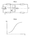
- An exemplary working curve A (s) is shown in FIG.
- a plurality of working curves for body deformations A ⁇ (s) are stored in the memory, which can be used by the computing unit 21 in the manner described above.
- FIG. 3 which represents a motor vehicle with a vehicle longitudinal axis A-A ', an exemplary angle ⁇ to the vehicle longitudinal axis A-A' located. Also shown is an exemplary body deformation s, starting from a fictitious bumper of the vehicle along the longitudinal axis A-A 'in the crumple zone 4 of the vehicle.
- the acceleration sensor 1 as well as the associated processor are arranged in a common control device approximately in the vehicle center.
- FIG. 2 shows a flow chart of the method according to the invention.
- the occupant protection system initializes and enters the state S1, where it continuously checks with step S2 whether the acceleration a has exceeded a minimum value ma, which causes a start of the impact calculations (j). If the minimum acceleration ma is detected (j), then in step S3 the body deformation s is a function of the vehicle mass m, which is recorded Acceleration a and the stored working curve A (s) calculated according to the above provisos, before the impact velocity v 0 is calculated as a function f of the calculated body deformation s, the acceleration a and the time t in step S4 also according to the above equations.
- step S5 If the determined impact velocity v 0 proves to be stable (j) after several calculation runs in step S5, then the energy E e to be expected as a function f of, for example, the vehicle mass m, the impact velocity v 0 and the acceleration a is determined in step S6. If the impact speed is not yet stable (n) in step S5, a new calculation cycle of steps S3 and S4 is required.
- the trigger criterion for the occupant protection means is checked in step S7: If the body deformation s and the energy E e to be expected exceed the associated limit values G1 and G2 (j), the occupant protection means is triggered in step S8. If at least one of the limit values G1 or G2 is not exceeded by the assigned signal (n), the body deformation s is recalculated at a further time.
- the limit values G1 and / or G2 can be constant or variable.
Landscapes
- Engineering & Computer Science (AREA)
- Mechanical Engineering (AREA)
- Physics & Mathematics (AREA)
- Mathematical Physics (AREA)
- Theoretical Computer Science (AREA)
- General Physics & Mathematics (AREA)
- Air Bags (AREA)
- Automotive Seat Belt Assembly (AREA)
Claims (21)
- Procédé pour commander un moyen de protection des occupants d'un véhicule,
dans lequel la masse (m) du véhicule est introduite en tant que grandeur de calcul,
dans lequel une relation de dépendance entre une déformation (s) de la carrosserie et le travail (A(s)) à produire pour cela est introduite,
dans lequel l'accélération (a) du véhicule est détectée et
dans lequel le moyen de protection des occupants (3) est commandé en fonction de la masse (m) du véhicule, du travail (A(s)) et de l'accélération (a). - Procédé selon la revendication 1, dans lequel la déformation effective (s) de la carrosserie est déterminée en fonction de l'accélération (a), du travail (A) et de la masse (m) du véhicule.
- Procédé selon revendication 2, dans lequel la déformation effective (s) de la carrosserie est dérivée de l'équation

où m représente la masse du véhicule, a l'accélération, s la déformation de la carrosserie et A le travail nécessaire pour cela. - Procédé selon la revendication 2 ou la revendication 3, dans lequel le moyen de protection des occupants (3) est commandé en fonction de la déformation effective (s) de la carrosserie.
- Procédé selon une des revendications précédentes, dans lequel la vitesse de collision (v0) est obtenue en fonction de l'accélération (a), du travail (A) et de la masse (m) du véhicule.
- Procédé selon la revendication 5, dans lequel le moyen de protection des occupants (3) est commandé en fonction de la vitesse de collision (v0) obtenue.
- Procédé selon une des revendications 2 ou 3 et selon la revendication 5, dans lequel la vitesse de collision (v0) est dérivée de la déformation effective (s) de la carrosserie.
- Procédé selon la revendication 7, dans lequel la vitesse de collision (v0) est dérivée de la déformation effective (s) de la carrosserie en appliquant l'équation

où s représente la déformation effective de la carrosserie, v0 la vitesse de collision, a l'accélération et t le temps. - Procédé selon une des revendications 5 à 8, dans lequel la vitesse de collision (v0) est calculée à plusieurs instants (t) et dans lequel une vitesse de collision moyenne ou une vitesse de collision plus tardive après un phénomène transitoire est utilisée comme base pour de nouveaux calculs.
- Procédé selon une des revendications précédentes, dans lequel on détermine une absorption d'énergie qu'on doit encore attendre (Ee) pour le véhicule.
- Procédé selon la revendication 10, dans lequel l'absorption d'énergie escomptée Ee est obtenue en appliquant l'équation :

où m représente la masse du véhicule, a l'accélération, t le temps et v0 la vitesse de collision. - Procédé selon la revendication 4, dans lequel un déblocage (f) pour le moyen de protection des occupants (3) est émis lorsque la déformation effective (s) de la carrosserie dépasse une valeur limite (G1) dans un intervalle de temps prédéterminé qui suit le début de la collision.
- Procédé selon la revendication 4 et la revendication 10 ou la revendication 11, dans lequel un déblocage (f) pour le moyen de protection des occupants (3) est émis lorsque la déformation effective (s) de la carrosserie dépasse une valeur limite (G1) et qu'en même temps l'absorption d'énergie qu'on doit encore attendre (Ee) dépasse une autre valeur limite (G2).
- Procédé selon une des revendications précédentes, dans lequel il s'effectue une estimation d'une accélération (a(t+ Δt)) pour un instant futur ((t+ Δt)).
- Procédé selon la revendication 14, dans lequel, à l'aide de l'accélération estimée (a(t+ Δt)), on détermine une avancée estimée (x(t+ Δt)) des occupants pour cet instant futur et dans lequel un déblocage (f) pour le moyen de protection des occupants (3) est émis lorsque l'avancée future des occupants (x(t+ Δt)) dépasse une valeur de seuil.
- Procédé selon les revendications 14 ou 15, dans lequel la relation de dépendance entre la déformation (s) de la carrosserie et le travail (A(s)) à produire pour cela sont introduits en fonction de l'angle de collision (Aα(s)), auquel cas une accélération future est estimée pour chaque travail en fonction de l'angle et dans lequel il se produit une estimation de l'accélération (aα(t+ Δt)) pour l'instant futur ((t+ Δt)) sur la base de chaque courbe de travail fonction de l'angle de collision qui a été introduite (Aα(s)) qui a été introduite et dans lequel l'accélération (a) supposée pour l'instant futur ((t+ Δt)) est comparée avec l'accélération estimée (aα(t+ Δt)).
- Procédé selon la revendication 16, dans lequel la courbe de travail (Aα(s)) fonction de l'angle de collision qui est utilisée pour des calculs suivants est celle qui forme la base pour l'accélération estimée (aα(t+ Δt)) qui présente le plus petit écart par rapport à l'accélération supposée (a).
- Procédé selon la revendication 16, dans lequel la courbe de travail (Aα(s)) fonction de l'angle de travail de collision qui prédétermine l'angle de collision (α) est celle qui forme la base pour l'accélération estimée (aα(t+ Δt)) qui présente le plus petit écart par rapport à l'accélération supposée (a) et dans lequel un moyen de protection des occupants (3) est commandé en fonction de l'angle de collision (α) obtenu de cette façon.
- Procédé selon une des revendications précédentes, dans lequel le travail (A(s)) à produire pour une déformation (s) de la carrosserie est déterminé au cours d'un test de collision.
- Procédé selon la revendication 19, dans lequel le travail A(s)) à produire pour une déformation (s) de la carrosserie est déterminé dans un test de collision exécuté avec une haute vitesse de collision et dans un test de collision exécuté avec une basse vitesse de collision.
- Dispositif pour commander un moyen de protection des occupants d'un véhicule, comprenant
un capteur d'accélération (1) destiné à détecter une accélération (a) du véhicule,
une mémoire (22) dans laquelle sont enregistrés la masse (m) du véhicule et la relation de dépendance entre la déformation (s) de la carrosserie et le travail (A(s)) à produire pour cela, et
une unité de calcul (21) qui est conçue pour commander le moyen de protection des occupants (3) en fonction de l'accélération (a), du travail (A) et de la masse (m) du véhicule.
Applications Claiming Priority (3)
| Application Number | Priority Date | Filing Date | Title |
|---|---|---|---|
| DE19840440 | 1998-09-04 | ||
| DE19840440A DE19840440B4 (de) | 1998-09-04 | 1998-09-04 | Verfahren und Vorrichtung zum Steuern eines Insassenschutzmittels eines Fahrzeugs |
| PCT/DE1999/002801 WO2000014494A1 (fr) | 1998-09-04 | 1999-09-03 | Procede et dispositif pour commander un moyen de protection d'occupant d'un vehicule |
Publications (2)
| Publication Number | Publication Date |
|---|---|
| EP1110064A1 EP1110064A1 (fr) | 2001-06-27 |
| EP1110064B1 true EP1110064B1 (fr) | 2006-04-05 |
Family
ID=7879855
Family Applications (1)
| Application Number | Title | Priority Date | Filing Date |
|---|---|---|---|
| EP99955655A Expired - Lifetime EP1110064B1 (fr) | 1998-09-04 | 1999-09-03 | Procede et dispositif pour commander un moyen de protection d'occupant d'un vehicule |
Country Status (6)
| Country | Link |
|---|---|
| US (1) | US7499781B2 (fr) |
| EP (1) | EP1110064B1 (fr) |
| JP (1) | JP3523595B2 (fr) |
| KR (1) | KR100456165B1 (fr) |
| DE (2) | DE19840440B4 (fr) |
| WO (1) | WO2000014494A1 (fr) |
Families Citing this family (17)
| Publication number | Priority date | Publication date | Assignee | Title |
|---|---|---|---|---|
| DE10018985A1 (de) * | 2000-04-17 | 2001-10-18 | Delphi Tech Inc | Anordnung und Verfahren zur Steuerung der Auslösung eines Luftsacks |
| DE10134331C1 (de) * | 2001-07-14 | 2002-10-10 | Bosch Gmbh Robert | Verfahren und Vorrichtung bei der Ansteuerung der Auslösung von passiven Sicherheitssystemen sowie Anwenendung davon |
| US7191045B2 (en) | 2001-08-28 | 2007-03-13 | Robert Bosch Gmbh | Method for determining a trigger time for restraint means in a vehicle |
| DE10141886A1 (de) * | 2001-08-28 | 2003-03-20 | Bosch Gmbh Robert | Verfahren zur Bestimmung einer Auslösezeit für Rückhaltemittel in einem Fahrzeug |
| DE10160883B4 (de) * | 2001-12-12 | 2014-02-13 | Volkswagen Ag | Verfahren und Vorrichtung zur Erfassung der Unfallschwere eines Fahrzeugs |
| DE10361280A1 (de) * | 2003-12-24 | 2005-07-28 | Daimlerchrysler Ag | Kraftfahrzeug mit ansteuerbaren Aufprall-Sicherheitseinrichtungen |
| JP4210926B2 (ja) * | 2004-01-16 | 2009-01-21 | 株式会社デンソー | 乗員保護システム |
| DE102004003718A1 (de) * | 2004-01-24 | 2005-08-11 | Conti Temic Microelectronic Gmbh | Verfahren und Vorrichtung zum Auslösen eines Insassenschutzsystems |
| DE102004017066A1 (de) * | 2004-04-07 | 2005-10-27 | Daimlerchrysler Ag | Kraftfahrzeug mit Positionierungsmitteln für Fahrzeuginsassen |
| DE102005011244A1 (de) * | 2005-03-11 | 2006-09-21 | Robert Bosch Gmbh | Verfahren und Vorrichtung zum Schätzen von mindestens einem Merkmal |
| WO2007044997A2 (fr) * | 2005-10-13 | 2007-04-19 | Trw Automotive U.S. Llc | Procédé et appareil pour procurer une fonction de sécurité dans un système de retenue |
| DE102006008638B4 (de) * | 2006-02-24 | 2015-06-11 | Robert Bosch Gmbh | Verfahren und Vorrichtung zur Unfallklassifizierung für ein Fahrzeug |
| GB201105277D0 (en) * | 2011-03-29 | 2011-05-11 | Jaguar Cars | Speed and category trigger for an active device of a vehicle |
| JP5447997B2 (ja) * | 2011-10-31 | 2014-03-19 | 株式会社デンソー | 車両用データ記録装置 |
| JP5854426B2 (ja) * | 2012-02-16 | 2016-02-09 | 三菱自動車工業株式会社 | 衝突判別装置 |
| DE102012204856A1 (de) * | 2012-03-27 | 2013-10-02 | Robert Bosch Gmbh | Massekopplungsanordnung für ein Fahrzeug |
| DE102017208403A1 (de) * | 2017-05-18 | 2018-11-22 | Robert Bosch Gmbh | Verfahren und Vorrichtung zur Unfallerkennung in einem Fahrzeug |
Family Cites Families (13)
| Publication number | Priority date | Publication date | Assignee | Title |
|---|---|---|---|---|
| ATE27937T1 (de) * | 1984-03-31 | 1987-07-15 | Bosch Gmbh Robert | Schaltungsanordnung, insbesondere fuer ein rueckhaltesystem in kraftfahrzeugen. |
| US4995639A (en) * | 1988-09-02 | 1991-02-26 | Automotive Technologies International, Inc. | Vehicle crush zone crash sensor |
| DE3924507A1 (de) * | 1989-02-18 | 1990-08-23 | Bosch Gmbh Robert | Verfahren zur ausloesung von rueckhaltemitteln |
| JP2605922B2 (ja) * | 1990-04-18 | 1997-04-30 | 日産自動車株式会社 | 車両用安全装置 |
| US5249826A (en) * | 1991-10-03 | 1993-10-05 | Amerigon, Inc. | Inertial mass safety system activation for personal vehicles |
| US5518271A (en) * | 1991-10-03 | 1996-05-21 | Amerigon, Inc. | Inertial mass safety system activation of a seat belt restraint system in personal vehicles |
| US5164901A (en) * | 1991-12-05 | 1992-11-17 | Trw Vehicle Safety Systems Inc. | Method and apparatus for testing a vehicle occupant restraint system |
| DE4212421A1 (de) * | 1992-04-14 | 1993-10-28 | Bosch Gmbh Robert | Verfahren und Einrichtung zum Schutz von Fahrzeuginsassen |
| DE4213673C2 (de) * | 1992-04-25 | 1994-09-08 | Dornier Gmbh | Auslöseverfahren für ein Rückhaltesystem |
| DE4409711B4 (de) * | 1994-03-22 | 2005-08-04 | Robert Bosch Gmbh | Sicherheitseinrichtung für Fahrzeuginsassen |
| US5681057A (en) * | 1995-02-17 | 1997-10-28 | U.S. Electricar | Crash energy-management structure |
| JP4166293B2 (ja) * | 1996-09-20 | 2008-10-15 | 三菱電機株式会社 | 車両の衝突検出装置 |
| DE19724101A1 (de) * | 1997-06-07 | 1998-12-10 | Bayerische Motoren Werke Ag | Verfahren zur bedarfsgerechten Steuerung von Insassen-Sicherheitseinrichtungen |
-
1998
- 1998-09-04 DE DE19840440A patent/DE19840440B4/de not_active Expired - Fee Related
-
1999
- 1999-09-03 JP JP2000569193A patent/JP3523595B2/ja not_active Expired - Fee Related
- 1999-09-03 EP EP99955655A patent/EP1110064B1/fr not_active Expired - Lifetime
- 1999-09-03 WO PCT/DE1999/002801 patent/WO2000014494A1/fr not_active Ceased
- 1999-09-03 DE DE59913311T patent/DE59913311D1/de not_active Expired - Lifetime
- 1999-09-03 KR KR10-2001-7002874A patent/KR100456165B1/ko not_active Expired - Fee Related
-
2001
- 2001-03-05 US US09/799,751 patent/US7499781B2/en not_active Expired - Fee Related
Also Published As
| Publication number | Publication date |
|---|---|
| US7499781B2 (en) | 2009-03-03 |
| KR100456165B1 (ko) | 2004-11-09 |
| KR20010089184A (ko) | 2001-09-29 |
| JP2002524343A (ja) | 2002-08-06 |
| DE19840440B4 (de) | 2004-09-16 |
| WO2000014494A1 (fr) | 2000-03-16 |
| JP3523595B2 (ja) | 2004-04-26 |
| DE59913311D1 (de) | 2006-05-18 |
| EP1110064A1 (fr) | 2001-06-27 |
| US20010025215A1 (en) | 2001-09-27 |
| DE19840440A1 (de) | 2000-03-16 |
Similar Documents
| Publication | Publication Date | Title |
|---|---|---|
| EP1355805B1 (fr) | Procede pour declencher des moyens de retenue dans un vehicule a moteur | |
| DE60019355T2 (de) | Zündvorrichtung für ein Rückhaltesystem mit einer Aufprallerkennungsvorrichtung | |
| DE102005042252B4 (de) | Überschlagserfassungsvorrichtung und -verfahren für Fahrzeuge | |
| DE19840440B4 (de) | Verfahren und Vorrichtung zum Steuern eines Insassenschutzmittels eines Fahrzeugs | |
| DE60217741T2 (de) | Überrolldetektionssystem für Kraftfahrzeuge | |
| DE19743009B4 (de) | Verfahren und Vorrichtung zur Einzelpunktabfühlung von vorderen und seitlichen Aufschlagzusammenstoßbedingungen | |
| DE102017102751B4 (de) | Aktivierungssteuervorrichtung und Aktivierungssteuerverfahren für Insassenschutzvorrichtung | |
| EP1258399B2 (fr) | Procédé pour l'activation d'une application de protection de passager dans un véhicule à moteur | |
| DE69402594T2 (de) | Verfahren und Vorrichtung zum Rückhalten eines Insassen während eines Seitenaufpralls | |
| EP1528992B1 (fr) | Procede detecteur d'un processus de culbute | |
| DE4212421A1 (de) | Verfahren und Einrichtung zum Schutz von Fahrzeuginsassen | |
| DE60216605T2 (de) | Aktivierungsvorrichtung und steuerverfahren zum insassenschutz | |
| DE4324753A1 (de) | Auslösevorrichtung für eine Sicherheitseinrichtung zum Schutz von Fahrzeuginsassen | |
| DE102014221048B4 (de) | Fahrzeugkollisionsbestimmungsvorrichtung | |
| EP1697177B1 (fr) | Procede pour commander des moyens de protection de personnes | |
| DE102016217105B4 (de) | Verfahren zum Ansteuern eines Insassenschutzsystems eines Fahrzeugs und Steuergerät | |
| DE10017084C2 (de) | Steuervorrichtung für Insassenschutzmittel in einem Kraftfahrzeug | |
| EP1689624B1 (fr) | Dispositif de determination d'un point de rotation d'un vehicule autour d'un axe vertical de vehicule | |
| EP2454125B1 (fr) | Methode de determination de retournement | |
| EP0988180B1 (fr) | Dispositif pour commander un element de protection des occupants d'un vehicule a moteur | |
| DE19806836C1 (de) | Vorrichtung zum Steuern eines Insassenschutzmittels eines Kraftfahrzeugs, insbesondere zum Seitenaufprallschutz | |
| EP1306269B1 (fr) | Dispositif de déclenchement d'un dispositif de sécurité dans un véhicule automobile et méthode de commande d'un tel dispositif de déclenchement | |
| DE102005037961B4 (de) | Verfahren und Vorrichtung zur Erkennung eines seitlichen Aufprallortes | |
| DE102009029475B4 (de) | Verfahren zur Einstellung einer über einen Aktor betätigbaren Crashbox | |
| DE10329597B4 (de) | Auslöseeinheit für Sicherungseinrichtungen in einem Kraftfahrzeug |
Legal Events
| Date | Code | Title | Description |
|---|---|---|---|
| PUAI | Public reference made under article 153(3) epc to a published international application that has entered the european phase |
Free format text: ORIGINAL CODE: 0009012 |
|
| 17P | Request for examination filed |
Effective date: 20010102 |
|
| AK | Designated contracting states |
Kind code of ref document: A1 Designated state(s): DE FR GB IT |
|
| 17Q | First examination report despatched |
Effective date: 20040513 |
|
| GRAP | Despatch of communication of intention to grant a patent |
Free format text: ORIGINAL CODE: EPIDOSNIGR1 |
|
| GRAS | Grant fee paid |
Free format text: ORIGINAL CODE: EPIDOSNIGR3 |
|
| GRAA | (expected) grant |
Free format text: ORIGINAL CODE: 0009210 |
|
| AK | Designated contracting states |
Kind code of ref document: B1 Designated state(s): DE FR GB IT |
|
| REG | Reference to a national code |
Ref country code: GB Ref legal event code: FG4D Free format text: NOT ENGLISH |
|
| GBT | Gb: translation of ep patent filed (gb section 77(6)(a)/1977) |
Effective date: 20060426 |
|
| REF | Corresponds to: |
Ref document number: 59913311 Country of ref document: DE Date of ref document: 20060518 Kind code of ref document: P |
|
| ET | Fr: translation filed | ||
| PLBE | No opposition filed within time limit |
Free format text: ORIGINAL CODE: 0009261 |
|
| STAA | Information on the status of an ep patent application or granted ep patent |
Free format text: STATUS: NO OPPOSITION FILED WITHIN TIME LIMIT |
|
| 26N | No opposition filed |
Effective date: 20070108 |
|
| PGFP | Annual fee paid to national office [announced via postgrant information from national office to epo] |
Ref country code: IT Payment date: 20100924 Year of fee payment: 12 Ref country code: FR Payment date: 20101005 Year of fee payment: 12 |
|
| PGFP | Annual fee paid to national office [announced via postgrant information from national office to epo] |
Ref country code: GB Payment date: 20100921 Year of fee payment: 12 |
|
| PGFP | Annual fee paid to national office [announced via postgrant information from national office to epo] |
Ref country code: DE Payment date: 20100930 Year of fee payment: 12 |
|
| REG | Reference to a national code |
Ref country code: FR Ref legal event code: TP |
|
| REG | Reference to a national code |
Ref country code: GB Ref legal event code: 732E Free format text: REGISTERED BETWEEN 20110825 AND 20110831 |
|
| GBPC | Gb: european patent ceased through non-payment of renewal fee |
Effective date: 20110903 |
|
| PG25 | Lapsed in a contracting state [announced via postgrant information from national office to epo] |
Ref country code: IT Free format text: LAPSE BECAUSE OF NON-PAYMENT OF DUE FEES Effective date: 20110903 |
|
| REG | Reference to a national code |
Ref country code: FR Ref legal event code: ST Effective date: 20120531 |
|
| REG | Reference to a national code |
Ref country code: DE Ref legal event code: R119 Ref document number: 59913311 Country of ref document: DE Effective date: 20120403 |
|
| PG25 | Lapsed in a contracting state [announced via postgrant information from national office to epo] |
Ref country code: DE Free format text: LAPSE BECAUSE OF NON-PAYMENT OF DUE FEES Effective date: 20120403 |
|
| PG25 | Lapsed in a contracting state [announced via postgrant information from national office to epo] |
Ref country code: FR Free format text: LAPSE BECAUSE OF NON-PAYMENT OF DUE FEES Effective date: 20110930 Ref country code: GB Free format text: LAPSE BECAUSE OF NON-PAYMENT OF DUE FEES Effective date: 20110903 |