EP1689624B1 - Dispositif de determination d'un point de rotation d'un vehicule autour d'un axe vertical de vehicule - Google Patents
Dispositif de determination d'un point de rotation d'un vehicule autour d'un axe vertical de vehicule Download PDFInfo
- Publication number
- EP1689624B1 EP1689624B1 EP04762453A EP04762453A EP1689624B1 EP 1689624 B1 EP1689624 B1 EP 1689624B1 EP 04762453 A EP04762453 A EP 04762453A EP 04762453 A EP04762453 A EP 04762453A EP 1689624 B1 EP1689624 B1 EP 1689624B1
- Authority
- EP
- European Patent Office
- Prior art keywords
- vehicle
- rotation
- sensor
- centre
- yaw rate
- Prior art date
- Legal status (The legal status is an assumption and is not a legal conclusion. Google has not performed a legal analysis and makes no representation as to the accuracy of the status listed.)
- Expired - Lifetime
Links
- 230000008859 change Effects 0.000 claims description 10
- 230000006870 function Effects 0.000 claims description 10
- 230000003287 optical effect Effects 0.000 claims description 4
- 230000005484 gravity Effects 0.000 description 29
- 230000008901 benefit Effects 0.000 description 6
- 238000000034 method Methods 0.000 description 6
- 230000001133 acceleration Effects 0.000 description 5
- 238000005259 measurement Methods 0.000 description 4
- 238000004364 calculation method Methods 0.000 description 3
- 238000010586 diagram Methods 0.000 description 3
- 238000006073 displacement reaction Methods 0.000 description 3
- 230000008569 process Effects 0.000 description 3
- 230000009466 transformation Effects 0.000 description 3
- 101000986989 Naja kaouthia Acidic phospholipase A2 CM-II Proteins 0.000 description 2
- 208000032366 Oversensing Diseases 0.000 description 2
- 238000001514 detection method Methods 0.000 description 2
- 238000013508 migration Methods 0.000 description 2
- 230000005012 migration Effects 0.000 description 2
- 230000000737 periodic effect Effects 0.000 description 2
- 230000001681 protective effect Effects 0.000 description 2
- 238000013459 approach Methods 0.000 description 1
- 230000015556 catabolic process Effects 0.000 description 1
- 230000001419 dependent effect Effects 0.000 description 1
- 238000011156 evaluation Methods 0.000 description 1
- 238000010304 firing Methods 0.000 description 1
- 238000009434 installation Methods 0.000 description 1
- 230000010354 integration Effects 0.000 description 1
- 238000013507 mapping Methods 0.000 description 1
- 238000000691 measurement method Methods 0.000 description 1
- 238000012545 processing Methods 0.000 description 1
- 230000000630 rising effect Effects 0.000 description 1
- 238000001228 spectrum Methods 0.000 description 1
- 238000009987 spinning Methods 0.000 description 1
- 230000006641 stabilisation Effects 0.000 description 1
- 238000011105 stabilization Methods 0.000 description 1
- 230000002123 temporal effect Effects 0.000 description 1
- 238000012360 testing method Methods 0.000 description 1
- 230000036962 time dependent Effects 0.000 description 1
- 230000001960 triggered effect Effects 0.000 description 1
Images
Classifications
-
- B—PERFORMING OPERATIONS; TRANSPORTING
- B60—VEHICLES IN GENERAL
- B60W—CONJOINT CONTROL OF VEHICLE SUB-UNITS OF DIFFERENT TYPE OR DIFFERENT FUNCTION; CONTROL SYSTEMS SPECIALLY ADAPTED FOR HYBRID VEHICLES; ROAD VEHICLE DRIVE CONTROL SYSTEMS FOR PURPOSES NOT RELATED TO THE CONTROL OF A PARTICULAR SUB-UNIT
- B60W40/00—Estimation or calculation of non-directly measurable driving parameters for road vehicle drive control systems not related to the control of a particular sub unit, e.g. by using mathematical models
- B60W40/10—Estimation or calculation of non-directly measurable driving parameters for road vehicle drive control systems not related to the control of a particular sub unit, e.g. by using mathematical models related to vehicle motion
- B60W40/114—Yaw movement
-
- B—PERFORMING OPERATIONS; TRANSPORTING
- B60—VEHICLES IN GENERAL
- B60R—VEHICLES, VEHICLE FITTINGS, OR VEHICLE PARTS, NOT OTHERWISE PROVIDED FOR
- B60R21/00—Arrangements or fittings on vehicles for protecting or preventing injuries to occupants or pedestrians in case of accidents or other traffic risks
- B60R21/01—Electrical circuits for triggering passive safety arrangements, e.g. airbags, safety belt tighteners, in case of vehicle accidents or impending vehicle accidents
- B60R21/013—Electrical circuits for triggering passive safety arrangements, e.g. airbags, safety belt tighteners, in case of vehicle accidents or impending vehicle accidents including means for detecting collisions, impending collisions or roll-over
- B60R21/0132—Electrical circuits for triggering passive safety arrangements, e.g. airbags, safety belt tighteners, in case of vehicle accidents or impending vehicle accidents including means for detecting collisions, impending collisions or roll-over responsive to vehicle motion parameters, e.g. to vehicle longitudinal or transversal deceleration or speed value
-
- B—PERFORMING OPERATIONS; TRANSPORTING
- B60—VEHICLES IN GENERAL
- B60W—CONJOINT CONTROL OF VEHICLE SUB-UNITS OF DIFFERENT TYPE OR DIFFERENT FUNCTION; CONTROL SYSTEMS SPECIALLY ADAPTED FOR HYBRID VEHICLES; ROAD VEHICLE DRIVE CONTROL SYSTEMS FOR PURPOSES NOT RELATED TO THE CONTROL OF A PARTICULAR SUB-UNIT
- B60W40/00—Estimation or calculation of non-directly measurable driving parameters for road vehicle drive control systems not related to the control of a particular sub unit, e.g. by using mathematical models
- B60W40/10—Estimation or calculation of non-directly measurable driving parameters for road vehicle drive control systems not related to the control of a particular sub unit, e.g. by using mathematical models related to vehicle motion
- B60W40/11—Pitch movement
-
- B—PERFORMING OPERATIONS; TRANSPORTING
- B60—VEHICLES IN GENERAL
- B60W—CONJOINT CONTROL OF VEHICLE SUB-UNITS OF DIFFERENT TYPE OR DIFFERENT FUNCTION; CONTROL SYSTEMS SPECIALLY ADAPTED FOR HYBRID VEHICLES; ROAD VEHICLE DRIVE CONTROL SYSTEMS FOR PURPOSES NOT RELATED TO THE CONTROL OF A PARTICULAR SUB-UNIT
- B60W40/00—Estimation or calculation of non-directly measurable driving parameters for road vehicle drive control systems not related to the control of a particular sub unit, e.g. by using mathematical models
- B60W40/10—Estimation or calculation of non-directly measurable driving parameters for road vehicle drive control systems not related to the control of a particular sub unit, e.g. by using mathematical models related to vehicle motion
- B60W40/112—Roll movement
-
- B—PERFORMING OPERATIONS; TRANSPORTING
- B60—VEHICLES IN GENERAL
- B60R—VEHICLES, VEHICLE FITTINGS, OR VEHICLE PARTS, NOT OTHERWISE PROVIDED FOR
- B60R21/00—Arrangements or fittings on vehicles for protecting or preventing injuries to occupants or pedestrians in case of accidents or other traffic risks
- B60R21/01—Electrical circuits for triggering passive safety arrangements, e.g. airbags, safety belt tighteners, in case of vehicle accidents or impending vehicle accidents
- B60R21/013—Electrical circuits for triggering passive safety arrangements, e.g. airbags, safety belt tighteners, in case of vehicle accidents or impending vehicle accidents including means for detecting collisions, impending collisions or roll-over
- B60R2021/01313—Electrical circuits for triggering passive safety arrangements, e.g. airbags, safety belt tighteners, in case of vehicle accidents or impending vehicle accidents including means for detecting collisions, impending collisions or roll-over monitoring the vehicle steering system or the dynamic control system
-
- B—PERFORMING OPERATIONS; TRANSPORTING
- B60—VEHICLES IN GENERAL
- B60T—VEHICLE BRAKE CONTROL SYSTEMS OR PARTS THEREOF; BRAKE CONTROL SYSTEMS OR PARTS THEREOF, IN GENERAL; ARRANGEMENT OF BRAKING ELEMENTS ON VEHICLES IN GENERAL; PORTABLE DEVICES FOR PREVENTING UNWANTED MOVEMENT OF VEHICLES; VEHICLE MODIFICATIONS TO FACILITATE COOLING OF BRAKES
- B60T2230/00—Monitoring, detecting special vehicle behaviour; Counteracting thereof
- B60T2230/02—Side slip angle, attitude angle, floating angle, drift angle
-
- B—PERFORMING OPERATIONS; TRANSPORTING
- B60—VEHICLES IN GENERAL
- B60W—CONJOINT CONTROL OF VEHICLE SUB-UNITS OF DIFFERENT TYPE OR DIFFERENT FUNCTION; CONTROL SYSTEMS SPECIALLY ADAPTED FOR HYBRID VEHICLES; ROAD VEHICLE DRIVE CONTROL SYSTEMS FOR PURPOSES NOT RELATED TO THE CONTROL OF A PARTICULAR SUB-UNIT
- B60W2520/00—Input parameters relating to overall vehicle dynamics
- B60W2520/14—Yaw
-
- B—PERFORMING OPERATIONS; TRANSPORTING
- B60—VEHICLES IN GENERAL
- B60W—CONJOINT CONTROL OF VEHICLE SUB-UNITS OF DIFFERENT TYPE OR DIFFERENT FUNCTION; CONTROL SYSTEMS SPECIALLY ADAPTED FOR HYBRID VEHICLES; ROAD VEHICLE DRIVE CONTROL SYSTEMS FOR PURPOSES NOT RELATED TO THE CONTROL OF A PARTICULAR SUB-UNIT
- B60W2520/00—Input parameters relating to overall vehicle dynamics
- B60W2520/20—Sideslip angle
Definitions
- the invention relates to a device for determining a pivot point of a vehicle about a vehicle vertical axis according to the preamble of the independent claim.
- a control device for occupant protection means in a motor vehicle is known.
- the use of tire sensors on the vehicle wheels is proposed in addition to a longitudinal acceleration sensor.
- the measurement data of the wheel load changes which these tire sensors detect allow an evaluation unit to calculate slow tilting movements of the vehicle.
- By means of the measurement data of an additional steering angle sensor and dynamic driving state changes can be detected.
- Occupant protection devices for front and side impact protection as well as for rollover protection are triggered depending on the detected accident situation.
- the device according to the invention for determining a pivot point of a vehicle about a vehicle vertical axis has the advantage that the device determines the displacement of the pivot point, so that driving dynamics variables are related to the current correct pivot point.
- the pivot point In the case of skidding movements around the vehicle vertical axis, the pivot point is always in the area of the front of the vehicle at the beginning. In the course of the skidding movement, the pivot point moves toward the center of gravity of the vehicle.
- This pivotal displacement is now advantageously used for the correct determination of the driving dynamics variables.
- active control systems such as vehicle dynamics control (ESP) can be controlled more safely and personal protection devices such as belt tensioners or airbags can be activated much more safely and with greater reliability.
- ESP vehicle dynamics control
- the device according to the invention is particularly suitable for the roll-over sensing, which includes a combination of active and passive safety.
- the pivot point shift is determined as a function of the slip angle and the yaw rate.
- the slip angle indicates the angle between the vehicle longitudinal axis and the velocity vector.
- the yaw rate is the rotation of the vehicle about a vehicle vertical axis.
- the device additionally takes into account the change in the slip angle as a function of time in the determination of the pivot point.
- a high slip angle change indicates a breakaway of the vehicle and can be used to initiate the calculation of the pivot point.
- both the yaw rate and the slip angle can be determined via other driving dynamics variables such as the vehicle lateral acceleration or speed and the vehicle longitudinal acceleration and speed.
- the float angle can be determined equivalently via driving dynamics variables in the vehicle longitudinal direction and vehicle transverse direction. It is therefore not necessary to measure the yaw rate and the slip angle.
- the sensor system is provided for determining the float angle in the region of the rear of the vehicle.
- this sensor is also arranged on the vehicle front.
- this sensor is optically formed.
- the measuring principle is optical.
- an optical sensor system which monitors the mobile underground can be used for this purpose.
- the stochastic microstructure of the road surface is imaged onto a periodic prism grid in the sensor.
- the temporal frequencies that result from multiplying the altered microstructure by the periodic structure of the grating are integrated across the sensor array to obtain an average value.
- the grating period which is typically between 100 and 800 microns, should be consistent with the spatial frequency spectrum of the drivable surface.
- the speed can be calculated by counting signal periods that are directly proportional to the distance Vehicle is driven to be determined.
- a determination of the velocities in two dimensions is possible by segmenting the grating surface.
- Other possibilities are the detection of the direction of travel and thus the slip angle.
- other measuring methods for determining the slip angle are also possible. These generally include all sensor principles that can perform a speed or location measurement over ground. In addition to optical sensors, radar-based or ultrasonic sensors are also possible here. Another measurement method for detecting the slip angle can also be based on a location system such as the Global Positioning System.
- the pivot point can be determined with the yaw rate and the slip angle in such a way that stored values for the yaw rate and the slip angle are present in a table, in order then to determine the pivot point. This means that tests are carried out with the respective vehicle beforehand in order to determine therefrom values that can then be accessed to determine the current pivot point. Alternatively, it is possible to either empirically or analytically determine a function that reflects the relationship between the slip angle and yaw rate as well as the current pivot point.
- the current pivot point is as shown above for the vehicle dynamics control of use, since the vehicle dynamics control with the current pivot point driving dynamics variables, in particular the vehicle transverse speed can determine more accurate. This can be based on the vehicle control more accurate calculations on the current driving situation win and ensure a safe over the prior art control of the vehicle. Even for a personal protection system that activates personal protective equipment such as belt tensioners and airbags, the knowledge of the current pivot point for an optimal control of great advantage, since even here dynamic variables in the triggering algorithm and thus better this can be determined.
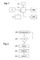
- FIG. 1 shows a block diagram of the device according to the invention.
- a float angle sensor S is connected to a first data input of a processor 10.
- This processor 10 may be a microprocessor or microcontroller.
- the processor 10 may be housed in a control unit, for example in a control unit for a vehicle dynamics control or for a personal protection system.
- a yaw rate sensor 11 is connected to a second data input of the processor 10.
- the processor 10 is connected to a memory 12 via a first data input / output.
- data can be permanently stored. It is possible that the memory 12 also has a volatile memory area.
- the processor 10 is coupled to a personal protection system RHS.
- a vehicle dynamics control ESP is connected via a third data input to the processor 10 to obtain the current pivot point. Also for the stabilization of the vehicle for which the vehicle dynamics control is responsible, the knowledge of the current pivot of great advantage.
- the processor 10 determines the current pivot using a table stored in the memory 12.
- the quantities ⁇ z denote the yaw rate, a y the lateral acceleration, a x the longitudinal acceleration, v x the speed in the longitudinal direction and ⁇ the slip angle.
- the slip angle is in the range of 4 ° to 8 ° and represents an uncritical size for the algorithms of the restraint systems.
- the vehicle dynamics control ESP controls the vehicle dynamics control ESP, so that dangerous situations detected and in situations where the vehicle threatens to break out , by precise braking of individual wheels, the vehicle is stabilized.
- the vehicle dynamics control ESP can no longer control, so the vehicle definitely breaks out, it comes to slip angles greater than 10 ° and then to a rotation of the vehicle about its vertical axis with or without a translational movement of the vehicle.
- an algorithm of a similar type can be used, which is activated due to the floating angle structure, the slip angle change. Since usually engages the rotation in the front area, a function can be created on the sideslip angle and the yaw rate that, for example, from a float angle of z. B. 25 ° and a yaw rate of 50 ° per second, the center of gravity of the rotation is shifted to the vehicle center of gravity. With increasing float angle and yaw rate inevitably results in the rotation of the vehicle to the vehicle's center of gravity. Thus, the rotation point change can be described as a function of the slip angle, yaw rate and possibly the slip angle change.
- a simple look-up table may be used, which first describes a linear relationship between the distance from the vehicle center of gravity to the pivot point as a function of the yaw rate after a breaking operation has been detected. That is, the slip angle serves as a condition for detecting the breaking operation, while the yaw rate is then used to determine the current turning point.
- the following table gives an example of a yaw rate and the distance of the sensor to determine the yaw rate Swing angle to the fulcrum. This distance and the distance of the sensor to the center of gravity gives the distance of the current center of rotation from the center of gravity.
- FIG. 2 explains in a flow chart the process that the device performs according to the invention.
- the float angle is determined with the sensor S.
- step 201 it is checked whether this slip angle is above a certain limit, here is taken as the limit 10 °. However, it is also possible to use 8 ° or a similar value. If the float angle is below this value, then no spin cycle is assumed and the process jumps back to step 200. However, if the slip angle is above 10 °, then jump to step 202 to use the yaw rate, as shown above, to determine the current pivot point.
- the rotation point change is determined in method step 203 with the above-mentioned table or an equation, in order then to determine the corresponding value, for example the distance center of gravity, in order to be able to optimally carry out the transformation of driving dynamics variables.
- the fulcrum is determined by combining the initial fulcrum assumed at the front of the vehicle and the fulcrum change to determine the current fulcrum.
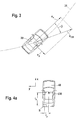
- FIG. 3 shows the basic dynamic parameters that are to be considered here.
- the vehicle 30 moves along a trajectory 31.
- the vehicle 30 has a speed component v x in the vehicle longitudinal direction and a speed component v y in the vehicle transverse direction. These two quantities yield a vector v CM , which describes the tangent to the trajectory 31.
- the angle ⁇ lies between the vector v CM and v x . This angle is the float angle.
- FIG. 4 describes the initial situation and the final situation during the spin movement.
- a vehicle 40 is provided with a center of gravity CM and a sensor S for determining the slip angle, wherein the sensor S is arranged in the rear of the vehicle, for example on the rear bumper.
- the distance of the sensor S to the center of gravity CM is indicated by the quantities 1 x in the vehicle longitudinal direction and 1 y in the vehicle transverse direction.
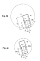
- FIG. 4b now shows the rotation of the vehicle around the front axle.
- the pivot point D is indicated on the vehicle front of the vehicle 41.
- the center of gravity CM is, of course, constant as is the installation location of the sensor S.
- the sensor S has the distance 1 d to the pivot point D relative to the logitudinal direction here.
- the sensor S is located at the rear of the vehicle and measures, for example, the longitudinal velocity v x, sensor and the lateral velocity v y , sensor .
- the sensor has the distance l sensor .
- VA l x . sensor . VA 2 + l y . sensor . VA 2 to the front axle and the distance l sensor .
- CM l x . sensor . CM 2 + l y . sensor . CM 2 to the main focus.
- the difference between the sensor and the front axle basically results as the distance since a rotation of the vehicle can always be initiated about the front wheels. Depending on the ground, yaw rate and so on. There is a possibility that the vehicle is rotated around the front wheels or the center of rotation is shifted from the front axle to the center of gravity. If this case occurs, then the vehicle rotates around the center of gravity and the above starting formula applies again.
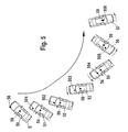
- FIG. 5 explains in a kind of time-lapse diagram the migration of the fulcrum.
- the vehicle is in position 50 with the center of gravity 59 and the pivot point 58 and the sensor S.
- the distance to the sensor is here maximum.
- the fulcrum has moved to the point 501, so that now the vehicle 51 rotates about the fulcrum 501.
- the fulcrum has moved to position 502 and has now moved closer to the center of gravity 59.
- the fulcrum has again moved a bit further, as in Figure 54, where the fulcrum 504 is already in the area of the windshield.
- the fulcrum 505 continues to approach the center of gravity 59, wherein in the image 57 the fulcrum 506 has reached the center of gravity 59. With a rising yaw rate and float angle the pivot point moves towards the center of gravity of the vehicle.
Landscapes
- Engineering & Computer Science (AREA)
- Mechanical Engineering (AREA)
- Physics & Mathematics (AREA)
- Automation & Control Theory (AREA)
- Mathematical Physics (AREA)
- Transportation (AREA)
- Vehicle Body Suspensions (AREA)
- Control Of Driving Devices And Active Controlling Of Vehicle (AREA)
- Automotive Seat Belt Assembly (AREA)
- Regulating Braking Force (AREA)
- Gyroscopes (AREA)
Abstract
Claims (8)
- Dispositif pour déterminer le point de rotation (D) d'un véhicule (30) autour d'un axe de hauteur du véhicule, caractérisé en ce que le dispositif est configuré de telle sorte que le dispositif détermine le point de rotation (D) en fonction d'un taux de lacet et d'un angle de flottement (β), et en ce que le dispositif présente une mémoire (12) dans laquelle sont stockées des données relatives au taux de lacet et à l'angle de flottement (β) , le dispositif déterminant le point de rotation (D) en fonction des données.
- Dispositif selon la revendication 1,
caractérisé en ce que le dispositif tient en plus compte d'une modification de l'angle de flottement (β) et/ou de la vitesse latérale (vy) pour déterminer le point de rotation (D). - Dispositif selon la revendication 1,
caractérisé en ce que le dispositif détermine le taux de lacet en fonction de grandeurs dynamiques de conduite linéaires. - Dispositif selon la revendication 1 ou 3,
caractérisé en ce que le dispositif détermine l'angle de flottement en fonction des grandeurs dynamiques de conduite linéaires. - Dispositif selon la revendication 1 ou 2,
caractérisé en ce qu'un dispositif de détection (S) est prévu dans la zone de l'arrière du véhicule pour déterminer l'angle de flottement (β). - Dispositif selon la revendication 5,
caractérisé en ce que le dispositif de détection (S) est réalisé sous forme optique et/ou à base d'ultrasons et/ou à base de radar et/ou à base de localisation. - Dispositif selon l'une des revendications précédentes, caractérisé en ce que le dispositif est connecté à un contrôleur dynamique de trajectoire (ESP) de telle sorte que le contrôleur dynamique de trajectoire (ESP) tient compte du point de rotation lors de la détermination des grandeurs dynamiques de conduite.
- Dispositif selon l'une des revendications précédentes, caractérisé en ce que le dispositif est connecté avec un système de protection des personnes (RHS) de telle sorte que le système de protection des personnes (RHS) tient compte du point de rotation (D) lors d'une commande des moyens de protection des personnes.
Applications Claiming Priority (2)
| Application Number | Priority Date | Filing Date | Title |
|---|---|---|---|
| DE10350920A DE10350920A1 (de) | 2003-10-31 | 2003-10-31 | Vorrichtung zur Bestimmung eines Drehpunkts eines Fahrzeugs um eine Fahrzeughochachse |
| PCT/DE2004/001603 WO2005044650A1 (fr) | 2003-10-31 | 2004-07-22 | Dispositif de determination d'un point de rotation d'un vehicule autour d'un axe de lacet de vehicule |
Publications (2)
| Publication Number | Publication Date |
|---|---|
| EP1689624A1 EP1689624A1 (fr) | 2006-08-16 |
| EP1689624B1 true EP1689624B1 (fr) | 2009-06-03 |
Family
ID=34485159
Family Applications (1)
| Application Number | Title | Priority Date | Filing Date |
|---|---|---|---|
| EP04762453A Expired - Lifetime EP1689624B1 (fr) | 2003-10-31 | 2004-07-22 | Dispositif de determination d'un point de rotation d'un vehicule autour d'un axe vertical de vehicule |
Country Status (7)
| Country | Link |
|---|---|
| US (1) | US7522991B2 (fr) |
| EP (1) | EP1689624B1 (fr) |
| JP (1) | JP2007509793A (fr) |
| CN (1) | CN100393563C (fr) |
| DE (2) | DE10350920A1 (fr) |
| ES (1) | ES2325400T3 (fr) |
| WO (1) | WO2005044650A1 (fr) |
Families Citing this family (15)
| Publication number | Priority date | Publication date | Assignee | Title |
|---|---|---|---|---|
| DE102005008976A1 (de) * | 2005-02-28 | 2006-08-31 | Robert Bosch Gmbh | Verfahren und Vorrichtung zum Bestimmen eines Initialschwimmwinkels zur Schleudererkennung bei Überrollsensierung |
| JP4513659B2 (ja) | 2005-06-14 | 2010-07-28 | トヨタ自動車株式会社 | 車両の操舵装置 |
| DE102008038642A1 (de) * | 2007-08-16 | 2009-02-19 | Continental Teves Ag & Co. Ohg | System und Verfahren zum Stabilisieren eines Kraftfahrzeugs |
| EP2261090B1 (fr) * | 2009-06-10 | 2013-08-28 | Robert Bosch Gmbh | Procédé et dispositif de contrôle pour analyser un mouvement rotatif d'un véhicule |
| JP5919889B2 (ja) | 2012-03-01 | 2016-05-18 | 株式会社ジェイテクト | 車両姿勢制御装置 |
| US9988043B2 (en) * | 2016-08-04 | 2018-06-05 | GM Global Technology Operations LLC | Methods and systems for determining a vehicle spin-out condition |
| DE102016009587B4 (de) | 2016-08-06 | 2021-03-11 | Daimler Ag | Verfahren zum Betreiben eines Kraftfahrzeugs mit einer aktiv steuerbaren Hinterachslenkung |
| DE102016009584A1 (de) | 2016-08-06 | 2018-02-08 | Daimler Ag | Verfahren zum Betreiben eines Kraftfahrzeugs mit einer aktiv steuerbaren Vorderachslenkung |
| DE102016009626A1 (de) | 2016-08-06 | 2018-02-08 | Daimler Ag | Verfahren zum Betreiben eines Kraftfahrzeugs mit einer aktiv steuerbaren Hinterachslenkung und einer aktiv steuerbaren Vorderachslenkung |
| DE102016009586A1 (de) | 2016-08-06 | 2018-02-08 | Daimler Ag | Kraftfahrzeug |
| DE102017008303A1 (de) | 2017-09-05 | 2018-10-11 | Daimler Ag | Verfahren zum Betreiben eines Kraftfahrzeugs mit einer aktiv steuerbaren Hinterachslenkung |
| US10158978B1 (en) * | 2017-10-16 | 2018-12-18 | Blackberry Limited | Updating a device position according to heading and movement |
| DE102017010500B4 (de) | 2017-11-13 | 2021-09-16 | Daimler Ag | Nutzfahrzeug |
| JP7803196B2 (ja) * | 2022-03-31 | 2026-01-21 | 日産自動車株式会社 | 車両制御方法及び車両制御装置 |
| DE102023004588B3 (de) | 2023-11-13 | 2024-08-01 | Mercedes-Benz Group AG | Verfahren zum Steuern und/oder Regeln eines Fahrzeugs bei einer Wendung auf der Stelle und eine Steuerungs- und/oder Regelungsvorrichtung hierfür |
Family Cites Families (14)
| Publication number | Priority date | Publication date | Assignee | Title |
|---|---|---|---|---|
| DE19605188C2 (de) * | 1996-02-13 | 2000-04-13 | Helmut Dick | Fahrzeuganhänger |
| US6230107B1 (en) * | 1996-03-29 | 2001-05-08 | Komatsu Ltd. | Vehicle speed detection system |
| DE19651123C1 (de) * | 1996-12-09 | 1998-06-18 | Siemens Ag | Steuervorrichtung in einem Kraftfahrzeug |
| DE19651124C1 (de) * | 1996-12-09 | 1998-05-28 | Siemens Ag | Steuervorrichtung für ein Schutzmittel zum Überrollschutz in einem Kraftfahrzeug |
| DE19742707C2 (de) * | 1997-09-26 | 2001-04-26 | Johannes Gubernath | Schlingerdämpfer |
| DE19830189A1 (de) * | 1998-05-14 | 1999-11-18 | Continental Teves Ag & Co Ohg | Verfahren zur Erhöhung der Kippstabilität eines Fahrzeugs |
| DE19812237C1 (de) * | 1998-03-20 | 1999-09-23 | Daimler Chrysler Ag | Verfahren zur Fahrdynamik-Regelung an einem Straßenfahrzeug |
| US6161905A (en) * | 1998-11-19 | 2000-12-19 | General Motors Corporation | Active brake control including estimation of yaw rate and slip angle |
| JP4087021B2 (ja) * | 1999-07-23 | 2008-05-14 | 本田技研工業株式会社 | 転回機構を備えた四輪車両 |
| US6304805B1 (en) * | 1999-07-21 | 2001-10-16 | Denso Corporation | Vehicle behavior estimating and controlling method and system as well as body slip angle estimating method and system |
| DE10017084C2 (de) * | 2000-02-07 | 2003-12-04 | Siemens Ag | Steuervorrichtung für Insassenschutzmittel in einem Kraftfahrzeug |
| DE10008550A1 (de) * | 2000-02-24 | 2001-09-13 | Bosch Gmbh Robert | Verfahren und Vorrichtung zur Bestimmung eines Bewegungsparameters eines Kraftfahrzeuges mit einem D-GPS-System |
| DE10015267C2 (de) * | 2000-03-28 | 2003-08-21 | Siemens Ag | Steuervorrichtung für Insassenschutzmittel in einem Kraftfahrzeug |
| US6829524B2 (en) * | 2001-08-20 | 2004-12-07 | Wisys Technology Foundation, Inc. | Method and apparatus for estimating yaw rate in a wheeled vehicle and stability system |
-
2003
- 2003-10-31 DE DE10350920A patent/DE10350920A1/de not_active Withdrawn
-
2004
- 2004-07-22 CN CNB2004800321914A patent/CN100393563C/zh not_active Expired - Fee Related
- 2004-07-22 US US10/532,376 patent/US7522991B2/en not_active Expired - Fee Related
- 2004-07-22 JP JP2006537042A patent/JP2007509793A/ja active Pending
- 2004-07-22 ES ES04762453T patent/ES2325400T3/es not_active Expired - Lifetime
- 2004-07-22 EP EP04762453A patent/EP1689624B1/fr not_active Expired - Lifetime
- 2004-07-22 DE DE502004009577T patent/DE502004009577D1/de not_active Expired - Lifetime
- 2004-07-22 WO PCT/DE2004/001603 patent/WO2005044650A1/fr not_active Ceased
Also Published As
| Publication number | Publication date |
|---|---|
| US7522991B2 (en) | 2009-04-21 |
| CN100393563C (zh) | 2008-06-11 |
| CN1874919A (zh) | 2006-12-06 |
| WO2005044650A1 (fr) | 2005-05-19 |
| ES2325400T3 (es) | 2009-09-03 |
| JP2007509793A (ja) | 2007-04-19 |
| DE10350920A1 (de) | 2005-05-25 |
| DE502004009577D1 (de) | 2009-07-16 |
| US20060150717A1 (en) | 2006-07-13 |
| EP1689624A1 (fr) | 2006-08-16 |
Similar Documents
| Publication | Publication Date | Title |
|---|---|---|
| EP1689624B1 (fr) | Dispositif de determination d'un point de rotation d'un vehicule autour d'un axe vertical de vehicule | |
| DE60217741T2 (de) | Überrolldetektionssystem für Kraftfahrzeuge | |
| DE102005042252B4 (de) | Überschlagserfassungsvorrichtung und -verfahren für Fahrzeuge | |
| DE10049911B4 (de) | Verfahren und Vorrichtung zur Aktivierung von Insassenschutzeinrichtungen | |
| EP1157898B1 (fr) | Procédé de détection d'entournement des voitures avec système de sécurité | |
| EP1436172B1 (fr) | Procede pour determiner lorsque le seuil de declenchement d'un systeme de retenue est atteint dans un vehicule | |
| DE19983044B4 (de) | Sicherheitsvorrichtung in einem Fahrzeug | |
| WO1993021043A1 (fr) | Procede et dispositif de protection des occupants d'un vehicule automobile | |
| EP0903267A1 (fr) | Appareil et méthode pour commander la mise à feu d' un dispositif de retenue dans un véhicule | |
| DE10234593B4 (de) | Vorrichtung zur Erkennung eines Fahrzeugüberschlags | |
| EP1110064B1 (fr) | Procede et dispositif pour commander un moyen de protection d'occupant d'un vehicule | |
| EP1945483B1 (fr) | Procédé et dispositif de détermination de l'angle de roulis pour dispositifs de protection des passagers | |
| EP1599364B1 (fr) | Procede et dispositif pour determiner la probabilite d'accident d'un vehicule | |
| EP1536986B1 (fr) | Dispositif pour identifier un tonneau effectue par un vehicule | |
| EP1846269B1 (fr) | Procede de declenchement destine a l'actionnement d'une estimation de vitesse laterale pour des dispositifs de protection des occupants d'un vehicule | |
| WO2011006457A1 (fr) | Procédé de détection de capotage | |
| EP1655180B1 (fr) | Procédé d'évaluation du mouvement de rotation d'un véhicule | |
| DE10361281A1 (de) | Verfahren zur Erkennung kritischer Fahrsituationen eines Fahrzeugs | |
| DE10242687B4 (de) | Vorrichtung zur Überrollerkennung in einem Fahrzeug | |
| WO2007014627A1 (fr) | Procede de commande d'un pretensionneur de ceinture et systeme de securite d'un pretensionneur de ceinture | |
| EP1820701B1 (fr) | Dispositif destiné à la commande de moyens de protection contre les tonneaux d'un véhicule | |
| EP1951555B1 (fr) | Procede et dispositif pour commander des moyens de protection des personnes lors d'un capotage | |
| DE102007019432B4 (de) | Vorrichtung und Verfahren zur Ansteuerung von Personenschutzmitteln | |
| DE102005023183B4 (de) | Verfahren und Vorrichtung zur Überschlagserkennung eines Fahrzeugs | |
| DE10343176A1 (de) | Anordnung zur Ansteuerung von einer Schutzvorrichtung in einem Fahrzeug |
Legal Events
| Date | Code | Title | Description |
|---|---|---|---|
| PUAI | Public reference made under article 153(3) epc to a published international application that has entered the european phase |
Free format text: ORIGINAL CODE: 0009012 |
|
| 17P | Request for examination filed |
Effective date: 20060531 |
|
| AK | Designated contracting states |
Kind code of ref document: A1 Designated state(s): DE ES FR SE |
|
| DAX | Request for extension of the european patent (deleted) | ||
| RBV | Designated contracting states (corrected) |
Designated state(s): DE ES FR SE |
|
| 17Q | First examination report despatched |
Effective date: 20081121 |
|
| GRAP | Despatch of communication of intention to grant a patent |
Free format text: ORIGINAL CODE: EPIDOSNIGR1 |
|
| RIC1 | Information provided on ipc code assigned before grant |
Ipc: B60T 8/17 20060101AFI20090211BHEP |
|
| GRAS | Grant fee paid |
Free format text: ORIGINAL CODE: EPIDOSNIGR3 |
|
| GRAA | (expected) grant |
Free format text: ORIGINAL CODE: 0009210 |
|
| AK | Designated contracting states |
Kind code of ref document: B1 Designated state(s): DE ES FR SE |
|
| REF | Corresponds to: |
Ref document number: 502004009577 Country of ref document: DE Date of ref document: 20090716 Kind code of ref document: P |
|
| REG | Reference to a national code |
Ref country code: ES Ref legal event code: FG2A Ref document number: 2325400 Country of ref document: ES Kind code of ref document: T3 |
|
| REG | Reference to a national code |
Ref country code: SE Ref legal event code: TRGR |
|
| PLBE | No opposition filed within time limit |
Free format text: ORIGINAL CODE: 0009261 |
|
| STAA | Information on the status of an ep patent application or granted ep patent |
Free format text: STATUS: NO OPPOSITION FILED WITHIN TIME LIMIT |
|
| 26N | No opposition filed |
Effective date: 20100304 |
|
| REG | Reference to a national code |
Ref country code: FR Ref legal event code: PLFP Year of fee payment: 12 |
|
| PGFP | Annual fee paid to national office [announced via postgrant information from national office to epo] |
Ref country code: ES Payment date: 20150723 Year of fee payment: 12 |
|
| PGFP | Annual fee paid to national office [announced via postgrant information from national office to epo] |
Ref country code: FR Payment date: 20150730 Year of fee payment: 12 Ref country code: SE Payment date: 20150724 Year of fee payment: 12 |
|
| REG | Reference to a national code |
Ref country code: SE Ref legal event code: EUG |
|
| PG25 | Lapsed in a contracting state [announced via postgrant information from national office to epo] |
Ref country code: FR Free format text: LAPSE BECAUSE OF NON-PAYMENT OF DUE FEES Effective date: 20160801 Ref country code: SE Free format text: LAPSE BECAUSE OF NON-PAYMENT OF DUE FEES Effective date: 20160723 |
|
| REG | Reference to a national code |
Ref country code: FR Ref legal event code: ST Effective date: 20170331 |
|
| PG25 | Lapsed in a contracting state [announced via postgrant information from national office to epo] |
Ref country code: ES Free format text: LAPSE BECAUSE OF NON-PAYMENT OF DUE FEES Effective date: 20160723 |
|
| REG | Reference to a national code |
Ref country code: ES Ref legal event code: FD2A Effective date: 20181129 |
|
| PGFP | Annual fee paid to national office [announced via postgrant information from national office to epo] |
Ref country code: DE Payment date: 20190924 Year of fee payment: 16 |
|
| REG | Reference to a national code |
Ref country code: DE Ref legal event code: R084 Ref document number: 502004009577 Country of ref document: DE |
|
| REG | Reference to a national code |
Ref country code: DE Ref legal event code: R119 Ref document number: 502004009577 Country of ref document: DE |
|
| PG25 | Lapsed in a contracting state [announced via postgrant information from national office to epo] |
Ref country code: DE Free format text: LAPSE BECAUSE OF NON-PAYMENT OF DUE FEES Effective date: 20210202 |